SKODA OCTAVIA 2015 3.G / (5E) Owner's Manual
Manufacturer: SKODA, Model Year: 2015, Model line: OCTAVIA, Model: SKODA OCTAVIA 2015 3.G / (5E)Pages: 268, PDF Size: 37.54 MB
Page 101 of 268
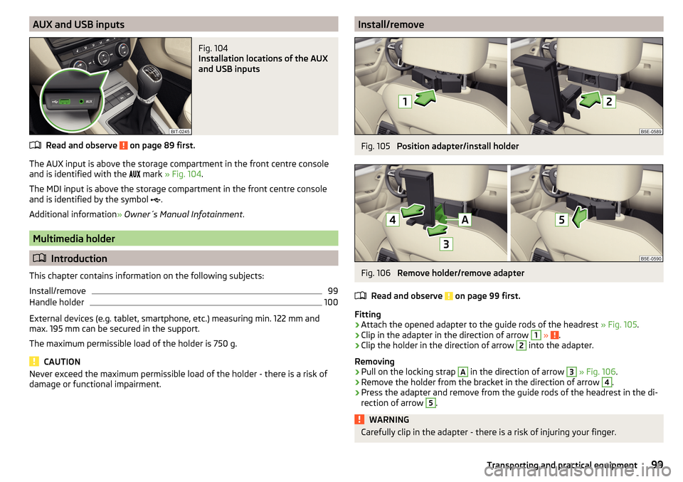
AUX and USB inputsFig. 104
Installation locations of the AUX
and USB inputs
Read and observe on page 89 first.
The AUX input is above the storage compartment in the front centre console and is identified with the mark
» Fig. 104 .
The MDI input is above the storage compartment in the front centre console
and is identified by the symbol .
Additional information » Owner´s Manual Infotainment .
Multimedia holder
Introduction
This chapter contains information on the following subjects:
Install/remove
99
Handle holder
100
External devices (e.g. tablet, smartphone, etc.) measuring min. 122 mm and
max. 195 mm can be secured in the support.
The maximum permissible load of the holder is 750 g.
CAUTION
Never exceed the maximum permissible load of the holder - there is a risk of
damage or functional impairment.Install/removeFig. 105
Position adapter/install holder
Fig. 106
Remove holder/remove adapter
Read and observe
on page 99 first.
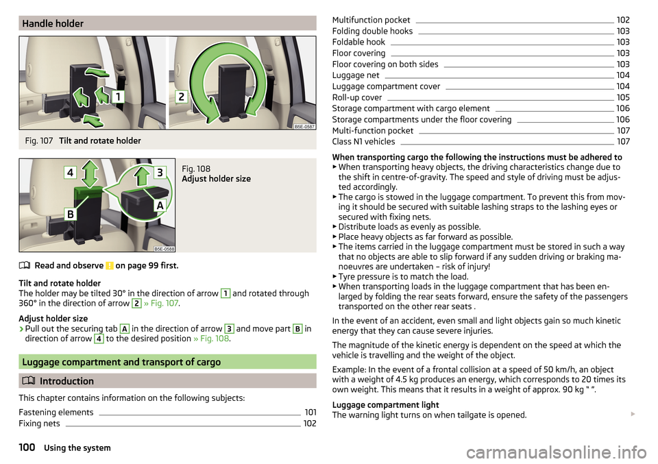
Fitting
›
Attach the opened adapter to the guide rods of the headrest » Fig. 105.
›
Clip in the adapter in the direction of arrow
1
» .
›
Clip the holder in the direction of arrow
2
into the adapter.
Removing
›
Pull on the locking strap
A
in the direction of arrow
3
» Fig. 106 .
›
Remove the holder from the bracket in the direction of arrow
4
.
›
Press the adapter and remove from the guide rods of the headrest in the di-
rection of arrow
5
.
WARNINGCarefully clip in the adapter - there is a risk of injuring your finger.99Transporting and practical equipment
Page 102 of 268
Handle holderFig. 107
Tilt and rotate holder
Fig. 108
Adjust holder size
Read and observe on page 99 first.
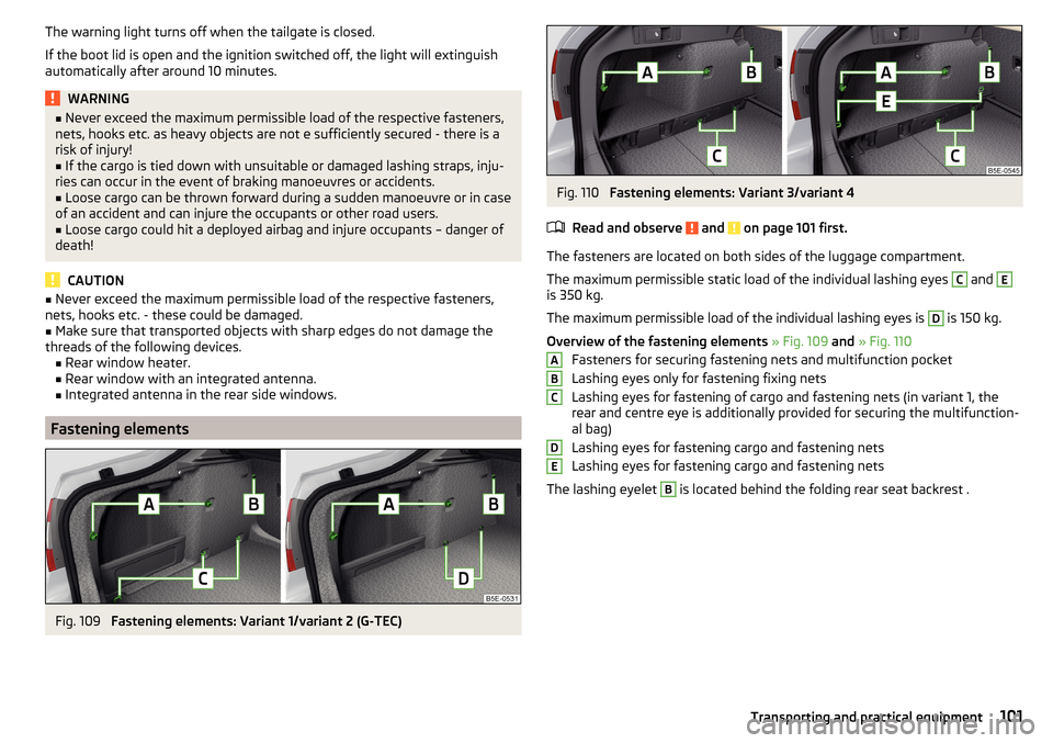
Tilt and rotate holder
The holder may be tilted 30° in the direction of arrow
1
and rotated through
360° in the direction of arrow
2
» Fig. 107 .
Adjust holder size
›
Pull out the securing tab
A
in the direction of arrow
3
and move part
B
in
direction of arrow
4
to the desired position » Fig. 108.
Luggage compartment and transport of cargo
Introduction
This chapter contains information on the following subjects:
Fastening elements
101
Fixing nets
102Multifunction pocket102Folding double hooks103
Foldable hook
103
Floor covering
103
Floor covering on both sides
103
Luggage net
104
Luggage compartment cover
104
Roll-up cover
105
Storage compartment with cargo element
106
Storage compartments under the floor covering
106
Multi-function pocket
107
Class N1 vehicles
107
When transporting cargo the following the instructions must be adhered to
▶ When transporting heavy objects, the driving characteristics change due to
the shift in centre-of-gravity. The speed and style of driving must be adjus-
ted accordingly.
▶ The cargo is stowed in the luggage compartment. To prevent this from mov-
ing it should be secured with suitable lashing straps to the lashing eyes or
secured with fixing nets.
▶ Distribute loads as evenly as possible.
▶ Place heavy objects as far forward as possible.
▶ The items carried in the luggage compartment must be stored in such a way
that no objects are able to slip forward if any sudden driving or braking ma-
noeuvres are undertaken – risk of injury!
▶ Tyre pressure is to match the load.
▶ When transporting loads in the luggage compartment that has been en-
larged by folding the rear seats forward, ensure the safety of the passengers
transported on the other rear seats .
In the event of an accident, even small and light objects gain so much kinetic
energy that they can cause severe injuries.
The magnitude of the kinetic energy is dependent on the speed at which the
vehicle is travelling and the weight of the object.
Example: In the event of a frontal collision at a speed of 50 km/h, an object
with a weight of 4.5 kg produces an energy, which corresponds to 20 times its
own weight. This means that it results in a weight of approx. 90 kg “ ”.
Luggage compartment light
The warning light turns on when tailgate is opened.
100Using the system
Page 103 of 268
The warning light turns off when the tailgate is closed.
If the boot lid is open and the ignition switched off, the light will extinguish
automatically after around 10 minutes.WARNING■ Never exceed the maximum permissible load of the respective fasteners,
nets, hooks etc. as heavy objects are not e sufficiently secured - there is a
risk of injury!■
If the cargo is tied down with unsuitable or damaged lashing straps, inju-
ries can occur in the event of braking manoeuvres or accidents.
■
Loose cargo can be thrown forward during a sudden manoeuvre or in case
of an accident and can injure the occupants or other road users.
■
Loose cargo could hit a deployed airbag and injure occupants – danger of
death!
CAUTION
■ Never exceed the maximum permissible load of the respective fasteners,
nets, hooks etc. - these could be damaged.■
Make sure that transported objects with sharp edges do not damage the
threads of the following devices. ■Rear window heater.
■ Rear window with an integrated antenna.
■ Integrated antenna in the rear side windows.
Fastening elements
Fig. 109
Fastening elements: Variant 1/variant 2 (G-TEC)
Fig. 110
Fastening elements: Variant 3/variant 4
Read and observe
and on page 101 first.
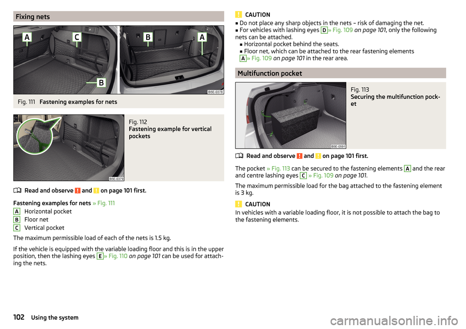
The fasteners are located on both sides of the luggage compartment.
The maximum permissible static load of the individual lashing eyes
C
and
E
is 350 kg.
The maximum permissible load of the individual lashing eyes is
D
is 150 kg.
Overview of the fastening elements » Fig. 109 and » Fig. 110
Fasteners for securing fastening nets and multifunction pocket
Lashing eyes only for fastening fixing nets
Lashing eyes for fastening of cargo and fastening nets (in variant 1, the
rear and centre eye is additionally provided for securing the multifunction-
al bag)
Lashing eyes for fastening cargo and fastening nets
Lashing eyes for fastening cargo and fastening nets
The lashing eyelet
B
is located behind the folding rear seat backrest .
ABCDE101Transporting and practical equipment
Page 104 of 268
Fixing netsFig. 111
Fastening examples for nets
Fig. 112
Fastening example for vertical
pockets
Read and observe and on page 101 first.
Fastening examples for nets » Fig. 111
Horizontal pocket
Floor net
Vertical pocket
The maximum permissible load of each of the nets is 1.5 kg.
If the vehicle is equipped with the variable loading floor and this is in the upper
position, then the lashing eyes
E
» Fig. 110 on page 101 can be used for attach-
ing the nets.
ABCCAUTION■ Do not place any sharp objects in the nets – risk of damaging the net.■For vehicles with lashing eyes D» Fig. 109 on page 101 , only the following
nets can be attached. ■ Horizontal pocket behind the seats.
■ Floor net, which can be attached to the rear fastening elementsA
» Fig. 109 on page 101 in the rear area.
Multifunction pocket
Fig. 113
Securing the multifunction pock-
et
Read and observe and on page 101 first.
The pocket » Fig. 113 can be secured to the fastening elements
A
and the rear
and centre lashing eyes
C
» Fig. 109 on page 101 .
The maximum permissible load for the bag attached to the fastening element
is 3 kg.
CAUTION
In vehicles with a variable loading floor, it is not possible to attach the bag to
the fastening elements.102Using the system
Page 105 of 268
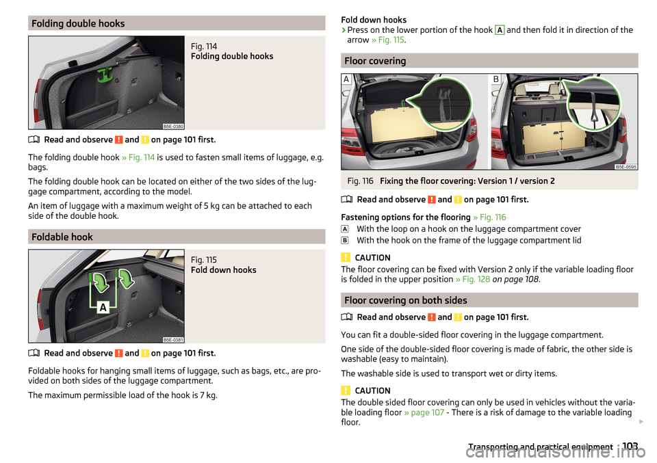
Folding double hooksFig. 114
Folding double hooks
Read and observe and on page 101 first.
The folding double hook » Fig. 114 is used to fasten small items of luggage, e.g.
bags.
The folding double hook can be located on either of the two sides of the lug-
gage compartment, according to the model.
An item of luggage with a maximum weight of 5 kg can be attached to each
side of the double hook.
Foldable hook
Fig. 115
Fold down hooks
Read and observe and on page 101 first.
Foldable hooks for hanging small items of luggage, such as bags, etc., are pro- vided on both sides of the luggage compartment.
The maximum permissible load of the hook is 7 kg.
Fold down hooks›Press on the lower portion of the hook A and then fold it in direction of the
arrow » Fig. 115 .
Floor covering
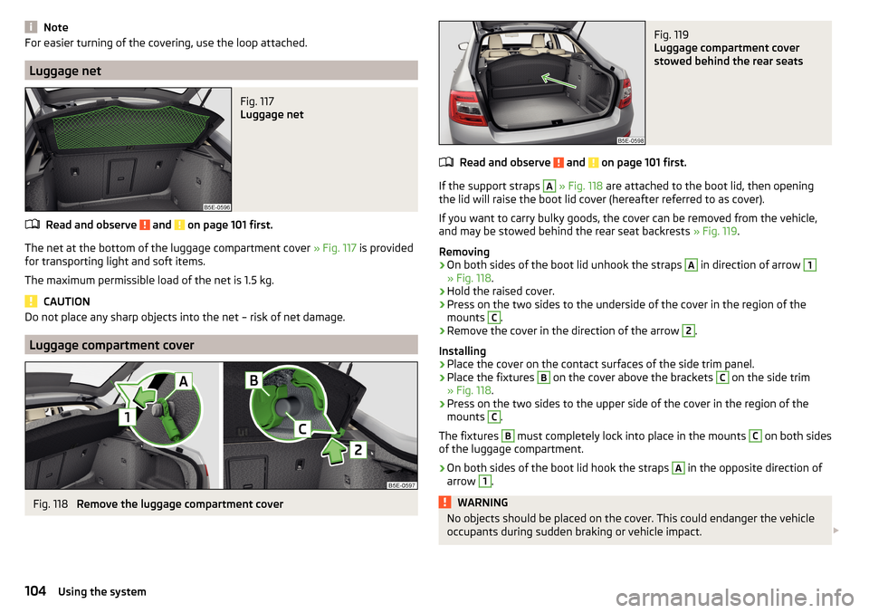
Fig. 116
Fixing the floor covering: Version 1 / version 2
Read and observe
and on page 101 first.
Fastening options for the flooring » Fig. 116
With the loop on a hook on the luggage compartment cover
With the hook on the frame of the luggage compartment lid
CAUTION
The floor covering can be fixed with Version 2 only if the variable loading floor
is folded in the upper position » Fig. 128 on page 108 .
Floor covering on both sides
Read and observe
and on page 101 first.
You can fit a double-sided floor covering in the luggage compartment.
One side of the double-sided floor covering is made of fabric, the other side is
washable (easy to maintain).
The washable side is used to transport wet or dirty items.
CAUTION
The double sided floor covering can only be used in vehicles without the varia-
ble loading floor » page 107 - There is a risk of damage to the variable loading
floor. 103Transporting and practical equipment
Page 106 of 268
NoteFor easier turning of the covering, use the loop attached.
Luggage net
Fig. 117
Luggage net
Read and observe and on page 101 first.
The net at the bottom of the luggage compartment cover » Fig. 117 is provided
for transporting light and soft items.
The maximum permissible load of the net is 1.5 kg.
CAUTION
Do not place any sharp objects into the net – risk of net damage.
Luggage compartment cover
Fig. 118
Remove the luggage compartment cover
Fig. 119
Luggage compartment cover
stowed behind the rear seats
Read and observe and on page 101 first.
If the support straps
A
» Fig. 118 are attached to the boot lid, then opening
the lid will raise the boot lid cover (hereafter referred to as cover).
If you want to carry bulky goods, the cover can be removed from the vehicle, and may be stowed behind the rear seat backrests » Fig. 119.
Removing
›
On both sides of the boot lid unhook the straps
A
in direction of arrow
1
» Fig. 118 .
›
Hold the raised cover.
›
Press on the two sides to the underside of the cover in the region of the
mounts
C
.
›
Remove the cover in the direction of the arrow
2
.
Installing
›
Place the cover on the contact surfaces of the side trim panel.
›
Place the fixtures
B
on the cover above the brackets
C
on the side trim
» Fig. 118 .
›
Press on the two sides to the upper side of the cover in the region of the
mounts
C
.
The fixtures
B
must completely lock into place in the mounts
C
on both sides
of the luggage compartment.
›
On both sides of the boot lid hook the straps
A
in the opposite direction of
arrow
1
.
WARNINGNo objects should be placed on the cover. This could endanger the vehicle
occupants during sudden braking or vehicle impact. 104Using the system
Page 107 of 268

CAUTION■When closing the boot lid, jamming and damage to the cover or the side trim
panel can occur if handled incorrectly. The following guidelines must be ob-
served. ■ The recesses in the cover B
» Fig. 118 must lock in the holders in the side
trim panel
C
.
■ The items which are transported must not exceed the height of the cover.
■ The cover must not be jammed in the surrounding seal of the luggage com-
partment lid when it is in the raised position. ■ There must be no object in the gap between the cover in the raise position
and the rear backrest.
Roll-up cover
Fig. 120
Roll-up cover: pull out/roll/remove
Fig. 121
Remove the side panels of the luggage compartment/stow the
roll-up luggage compartment cover
Read and observe and on page 101 first.
Extending
›
Grasp the cover on the handle
A
and pull it out in the direction of the arrow
1
until it clicks » Fig. 120.
Retracting
›
Push the cover in the area of handle
A
in the direction of the arrow
2
» Fig. 120 .
The cover rolls up automatically.
Removing/inserting
The fully rolled luggage compartment cover can be removed.
›
Press on the side of the cross bar in the direction of arrow
3
and remove
the cover in the arrow direction
4
» Fig. 120 .
Insertion takes place in reverse order.
Stowage
If the vehicle is equipped with the variable loading floor, then the removable
roll-up luggage compartment cover can be stowed in the recesses of the lug-
gage compartment side trim.
›
Fold the variable loading floor into the upper position » page 108.
›
Remove the side covers of the luggage compartment in the direction of the
arrow
1
» Fig. 121 .
›
Remove the roll-up luggage compartment cover » Fig. 120.
›
Insert the front part of the roll-up luggage compartment cover under a por-
tion of the side trim
D
» Fig. 121 on the left.
›
Fold the rear part of the roll-up luggage compartment cover in the direction
of arrow
2
» .
›
Replace the side trims of the luggage compartment in the opposite direction
of the arrow
1
.
›
Fold out the variable loading floor to the upper position » page 108.
WARNINGNo objects should be placed on the foldable boot cover. This could endan-
ger the vehicle occupants during sudden braking or vehicle impact.
CAUTION
If you want to stow the roll-up luggage compartment cover and the roof rack
at the same time , then it is necessary that the rear part of the roll-up luggage
compartment is covering the rear roof rack.105Transporting and practical equipment
Page 108 of 268
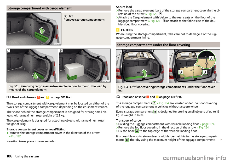
Storage compartment with cargo elementFig. 122
Remove storage compartment
Fig. 123
Removing cargo element/example on how to mount the load by
means of the cargo element
Read and observe
and on page 101 first.
The storage compartment with cargo element may be located on either of the
two sides of the luggage compartment, depending on the equipment variant.
The space behind the storage compartment is designed for storing small ob-
jects with a maximum total weight of 2.5 kg.
The cargo element is designed for attaching objects with a maximum total
weight of 8 kg.
Storage compartment cover removal/fitting
›
Remove the storage compartment cover in the direction of the arrow
» Fig. 122 .
Insertion takes place in reverse order.
Secure load›Remove the cargo element (part of the storage compartment cover) in the di-
rection of the arrow » Fig. 123-
.›
Attach the Cargo element with Velcro to the rear seats on the floor of the
luggage compartment » Fig. 123 -
or attach to the fabric side of the dou-
ble-sided floor covering.
CAUTION
When using the storage compartment, take care not to damage it or the lug-
gage compartment lining.
Storage compartments under the floor covering
Fig. 124
Lift floor covering/storage compartments under the floor cover-
ing
Read and observe
and on page 101 first.
The storage compartments
B
» Fig. 124 are located under the floor covering
of the luggage compartment in vehicles without a spare wheel.
Every storage compartment
B
is designed for storing small objects of up to 15
kg. in weight in total.
Transport of cargo
›
Dividing the luggage compartment with variable loading floor » page 109.
›
Remove the fog floor covering in the direction of the arrow » Fig. 124.
›
Fix the hook
A
to the top edge of the variable loading floor.
It is possible also to store objects with larger heights in the storage compart-
ments
B
, thereby using the maximum height of the luggage compartment.
106Using the system
Page 109 of 268
CAUTION■The following instructions must be observed to avoid damage to the storage
compartments. ■Do not stored any sharp objects in the storage compartments.
■ Do not place any point-pressure in the storage compartment.
■ Carefully place the items in the storage compartments.
Multi-function pocket
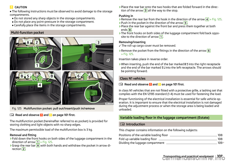
Fig. 125
Multifunction pocket: pull out/insert/push in/remove
Read and observe
and on page 101 first.
The multifunction pocket (hereinafter referred to as pocket) is provided for
storing clothing and light objects with no sharp edges.
The maximum permissible load of the multifunction box is 3 kg.
Removal and fitting
›
Fold down the front hooks on both sides of the luggage compartment in the
direction of arrow
1
» Fig. 125 .
›
Grasp the rear bar
A
with both hands and withdraw the pocket in arrow di-
rection
2
.
› Place the rear bar onto the two hooks that are folded forward in the direc-
tion of the arrow 3 all the way to the stop.
Pushing in›
Remove the rear bar from the hook in the direction of the arrow
4
» Fig. 125 .
›
Push in the pocket in the direction of the arrow
5
.
›
Place the rear bar against the front bar and press them together at both
ends
B
.
›
The front hooks on both sides of the luggage compartment fold back oppo-
site to the direction of arrow
1
.
Removing/inserting
The roll-up cargo cover must be removed.
›
Remove the pocket from the fittings in the direction of the arrow
6
» Fig. 125 .
Insertion takes place in reverse order.
›
When inserting, push the end of the bar marked
into the right receptacle
and the end of the bar marked
into the left receptacle. The arrows should
be pointing forward.
Class N1 vehicles
Read and observe
and on page 101 first.
In class N1 vehicles that are not fitted with a protective grille, a lashing set that
complies with the EN 12195 standard (1-4) must be used for fastening the load.
Proper functioning of the electrical installation is essential for safe vehicle op-
eration. It is important to ensure that the electrical installation is not damaged
during the adjustment process or when the storage area is being loaded and
unloaded.
Variable loading floor in the luggage compartment (Estate)
Introduction
This chapter contains information on the following subjects:
Positions of the variable loading floor
108
Fold up variable loading floor
108
Dividing the luggage compartment
109
107Transporting and practical equipment
Page 110 of 268
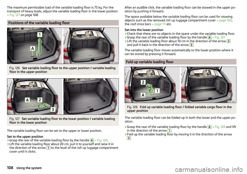
The maximum permissible load of the variable loading floor is 75 kg. For the
transport of heavy loads, adjust the variable loading floor in the lower position
» Fig. 127 on page 108 .
Positions of the variable loading floor
Fig. 126
Set variable loading floor to the upper position / variable loading
floor in the upper position
Fig. 127
Set variable loading floor to the lower position / variable loading
floor in the lower position
The variable loading floor can be set to the upper or lower position.
Set to the upper position
›
Grasp the rear of the variable loading floor by the handle
A
» Fig. 126 .
›
Lift the variable loading floor about 20 cm, pull it to yourself and raise it in
the direction of the arrow
1
to the level of the roll-up luggage compartment
cover until it clicks.
After an audible click, the variable loading floor can be stowed in the upper po-
sition by pushing it forward.
The space available below the variable loading floor can be used for stowing
objects such as the removed roll-up luggage compartment cover » page 105,
the roof cross bars » page 111 etc.
Set into the lower position›
Check that there are no objects in the space under the variable loading floor.
›
Grasp the rear of the variable loading floor by the handle
A
» Fig. 127 .
›
Lift the variable loading floor about 10 cm in the direction of the arrow
2
and pull it back in the direction of the arrow
3
.
The variable loading floor moves automatically to the lower position where it
can be stored by pressing it forward.
Fold up variable loading floor
Fig. 128
Fold up variable loading floor / folded variable cargo floor in the
upper position
The variable loading floor can be folded up in both the lower and the upper po-
sition.
›
Grasp the rear of the variable loading floor by the handle
A
» Fig. 128 and lift
in the direction of the arrow
1
.
›
Fold up the variable loading floor by moving it in the direction of the arrow
2
.
108Using the system