sensor SKODA OCTAVIA 2015 3.G / (5E) User Guide
[x] Cancel search | Manufacturer: SKODA, Model Year: 2015, Model line: OCTAVIA, Model: SKODA OCTAVIA 2015 3.G / (5E)Pages: 268, PDF Size: 37.54 MB
Page 116 of 268
Information on the cooling system
The cooling system operates only if the following conditions are met
» page 112 .
The warning light below the button
» Fig. 136 illuminates after activation,
even if not all of the conditions for the function of the cooling system have
been met. The lighting up of the indicator light in the button signals the opera-
tional readiness of the cooling system.
When the air distribution control is turned to position
the cooling system is
activated.
Note
During operation of the manual air conditioning, an increase in engine idle
speed may occur under certain circumstances in order to ensure sufficient
heating comfort.
Climatronic (automatic air conditioning)
Fig. 137
Controls the Climatronic
Read and observe
and on page 113 first.
The Climatronic in automatic mode ensures the best-possible setting of the
temperature of the out-flowing air, the blower stage and air distribution.
Individual functions can be set or switched on by turning the dial or pressing
the corresponding key. When the function is switched on, a warning light
lights up within or below the button.
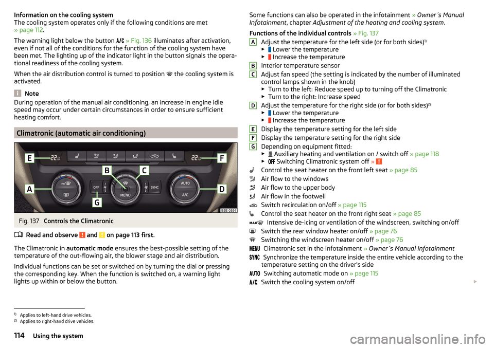
Some functions can also be operated in the infotainment » Owner´s Manual
Infotainment , chapter Adjustment of the heating and cooling system .
Functions of the individual controls » Fig. 137
Adjust the temperature for the left side (or for both sides) 1)
▶ Lower the temperature
▶ Increase the temperature
Interior temperature sensor
Adjust fan speed (the setting is indicated by the number of illuminated
control lamps shown in the knob) ▶ Turn to the left: Reduce speed up to turning off the Climatronic
▶ Turn to the right: Increase speed
Adjust the temperature for the right side (or for both sides) 2)
▶ Lower the temperature
▶ Increase the temperature
Display the temperature setting for the left side
Display the temperature setting for the right side
Depending on equipment fitted:
▶ Auxiliary heating and ventilation on / switch off
» page 118
▶ Switching Climatronic system off
»
Control the seat heater on the front left seat » page 85
Air flow to the windows
Air flow to the upper body
Air flow in the footwell
Switch recirculation on/off » page 115
Control the seat heater on the front right seat » page 85
Intensive de-icing or ventilation of the windscreen, switching on/off
Switch the rear window heater on/off » page 76
Switching the windscreen heater on/off » page 76
Climatronic set in the Infotainment » Owner´s Manual Infotainment
Synchronize the temperature inside the entire vehicle according to the
temperature setting on the driver's side
Switching automatic mode on » page 115
Switch the cooling system on/off
ABCDEFG1)
Applies to left-hand drive vehicles.
2)
Applies to right-hand drive vehicles.
114Using the system
Page 117 of 268
Setting temperature
The temperature can be adjusted on the Climatronic control unit or in the Info-
tainment » Owner´s Manual Infotainment , chapter Setting the heating and the
cooling system .
The temperature can be set between +16 °C and +29.5 °C. The temperature is
regulated automatically within this range.
Illuminates in the temperature display
then the Climatronic works with max-
imum cooling (temperature setting below +16 °C).
Illuminates in the temperature display
then the Climatronic works with maxi-
mum heating (temperature setting above +29.5 °C).
There is no automatic temperature control in the two end positions.WARNING■ Do not switch off the Climatronic system for longer than necessary.■Switch on the Climatronic system as soon as the windows mist up.
CAUTION
Do not cover the interior temperature sensor B » Fig. 137 as this could impair
the functioning of the Climatronic.
Note
■ During operation of the Climatronic, an increase in engine idle speed can oc-
cur under certain circumstances in order to ensure adequate heating comfort.■
When
is switched on, the air flow to the windows
is switched on. The
air flow to the windows will remain switched on after turning
off.
■
Holding the button
will turn on
automatically.
Climatronic - automatic operation
Read and observe
and on page 113 first.
The automatic mode is used in order to maintain a constant temperature and
to demist the windows in the interior of the car.
Automatic mode can be switched off by pressing one of the buttons for the air
distribution or by increasing/decreasing the blower speed. The temperature
regulation is continued.
Operating modes
Automatic mode works in three modes - moderate, medium, and intensive.
Setting the individual operating modes » Owner´s Manual Infotainment , chap-
ter Setting the heating and the cooling system .
After the automatic mode is switched on, Climatronic works in the last selec-
ted mode.
The currently selected mode is displayed in the Infotainment display.
Note
Climatronic is set to the medium setting at the factory.
Air distribution control
Read and observe
and on page 113 first.
The recirculation mode prevents contaminated outside air getting into the In-
terior of the vehicle.
In recirculated air mode air is sucked out of the interior of the vehicle and then
fed back into the interior.
Switching on/off
›
Press the button.
When the recirculation mode is activated, the warning light below the button
lights up.
Heating and manual air conditioning system
If the air distribution control is set to position when the recirculation modes
is switched on, the recirculated-air mode is switched off. Recirculated air mode
can be switched on again from this setting by repeatedly pressing the symbol
button .
When the is switched on and the temperature regulator is turned to the
left, the recirculated-air mode is switched on.
Climatronic
Climatronic may have an air quality sensor for the detection of the pollutant
concentration in the sucked-in air.
If a considerable increase in concentration of pollutants is recognised by the
air quality sensor, the recirculated air mode will be switched on automatically.
When the pollutant concentration decreases to the normal level, the recircula-
ted air mode is automatically switched off.
115Heating and ventilation
Page 137 of 268
Assist systems
General information
Introduction
This chapter contains information on the following subjects:
Radar sensor
135WARNINGThe following general information regarding the use of assistance systems
must be observed.■
The assistance systems only serve to support and do not relieve the driv-
er of the responsibility for driving the vehicle.
■
The increased safety provision, as well as the increased occupant protec-
tion provided by the assistance systems must not tempt you to take risks -
risk of accident!
■
Adjust the speed and driving style to the current visibility, weather, road
and traffic conditions.
■
The assistance systems have physical and system-related limitations. For
this reason, the driver may experience some undesired or delayed system
responses in certain situations. You should therefore always be alert and
ready to intervene!
■
Only activate, deactivate or set the assistance systems so that you have
the vehicle fully under control in every traffic situation - risk of accident!
Radar sensor
Fig. 154
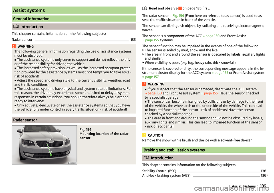
Mounting location of the radar
sensor
Read and observe on page 135 first.
The radar sensor » Fig. 154 (From here on referred to as sensor) is used to as-
sess the traffic situation in front of the vehicle.
The sensor can distinguish objects by radiating and receiving electromagnetic waves.
The sensor is a component of the ACC » page 150 and Front Assist
» page 155 systems.
The sensor function may be impaired in the events of one of the following. ▶ The sensor is soiled by mud, snow and the like.
▶ The area in front and around the sensor is obscured by labels, auxiliary lights
and similar.
▶ When visibility is poor, (e.g. fog, heavy rain, thick snowfall).
If the sensor is covered or dirty, the corresponding message appears in the in-
strument cluster display for the ACC system » page 155 or Front Assist system
» page 157 .
WARNING■
If you suspect that the sensor is damaged, deactivate the ACC system
» page 150 and Front Assist system » page 155. Have the sensor checked
by a specialist garage.■
The sensor can become misaligned by collisions or by damage to the front
of the vehicle, the wheel arch or the underside of the vehicle. This can lead
to impaired function of the sensor - risk of accidents! Have the sensor
checked by a specialist garage.
■
The area in front and around the sensor should not be obscured by labels,
auxiliary lights and similar. This can lead to impaired function of the sensor
- risk of accidents!
CAUTION
Remove the snow with a brush and the ice with a solvent-free de-icer.
Braking and stabilisation systems
Introduction
This chapter contains information on the following subjects:
Stability Control (ESC)
136
Anti-lock braking system (ABS)
136
135Assist systems
Page 142 of 268
NoteDuring an active intervention of the assistant, the brake lights do not light up.
ESC OFF ROADRead and observe
and on page 138 first.
The ESC OFF ROAD makes driving on a dirt roads easier, as no ESC interven-
tions occur when the vehicle is over or under steered.
TCSOFF ROAD
Read and observe
and on page 138 first.
The TCS OFF ROAD makes starting and driving on an unpaved surface easier as
it partially allows wheel-spin.
Note
When disabled, the TCS » page 136 OFF ROAD mode works without the sup-
port of the TCS OFF ROAD.
EDS OFF ROAD
Read and observe
and on page 138 first.
The EDS supports OFF ROAD vehicle traction when driving on a surface with
different grip under the drive wheels or when driving over bumps.
A spinning wheel or wheels are braked earlier and with more force than with
the intervention of the standard EDS system.
ABS OFF ROAD
Read and observe
and on page 138 first.
The ABS OFF ROAD supports the driver when braking on an unpaved surface
such as gravel, snow, etc.
The system generated by a controlled locking of the wheels braked wheel be-
fore a “wedge” of piled material, which shortens the braking distance.
The system is only available, if the front wheels are in the straight-ahead posi-
tion.
The system operates at speeds of up to 50 km/h.
Parking aid (ParkPilot)
Introduction
This chapter contains information on the following subjects:
Function
141
Display in the Infotainment display
142
Activation / deactivation
142
Automatic system activation when moving forward
143
The parking aid (hereinafter referred to as system) draws attention via acous-
tic signals or the Infotainment display when manoeuvring around obstacles in
the vicinity of the vehicle.
WARNING■ The general information relating to the use of assistance systems must
be observed » page 135, in section Introduction .■
Moving persons or objects may not be recognized by the system sensors.
■
Under certain circumstances, surfaces of certain objects and types of
clothing cannot reflect the system signals. For this reason, such people or
objects may not be recognised by the system sensors.
■
External noise sources may affect the signals of the system sensors. Un-
der adverse conditions, this may cause objects or people not to be recog-
nised by the system.
■
You should satisfy yourself before reversing that there is no small obsta-
cle, such as a rock, thin post, trailer drawbar etc., in front or behind your ve-
hicle. Such obstacles may not be recognised by the system sensors.
CAUTION
■ Keep the system sensors » Fig. 157 on page 141 clean, and free from snow
and ice, and do not cover with any objects of any kind, otherwise the system
functioning may be limited.■
Under adverse weather conditions (heavy rain, water vapour, very low or
high temperatures, etc.), the system function may be limited - “incorrect recog-
nition of obstacle”.
■
Accessories additionally installed on the vehicle rear, such as bicycle carriers,
can impair the system function.
Note
The display of obstacles in the Infotainment black and white display is descri-
bed in the » Owner´s Manual Infotainment , chapter CAR - vehicle settings .140Driving
Page 143 of 268
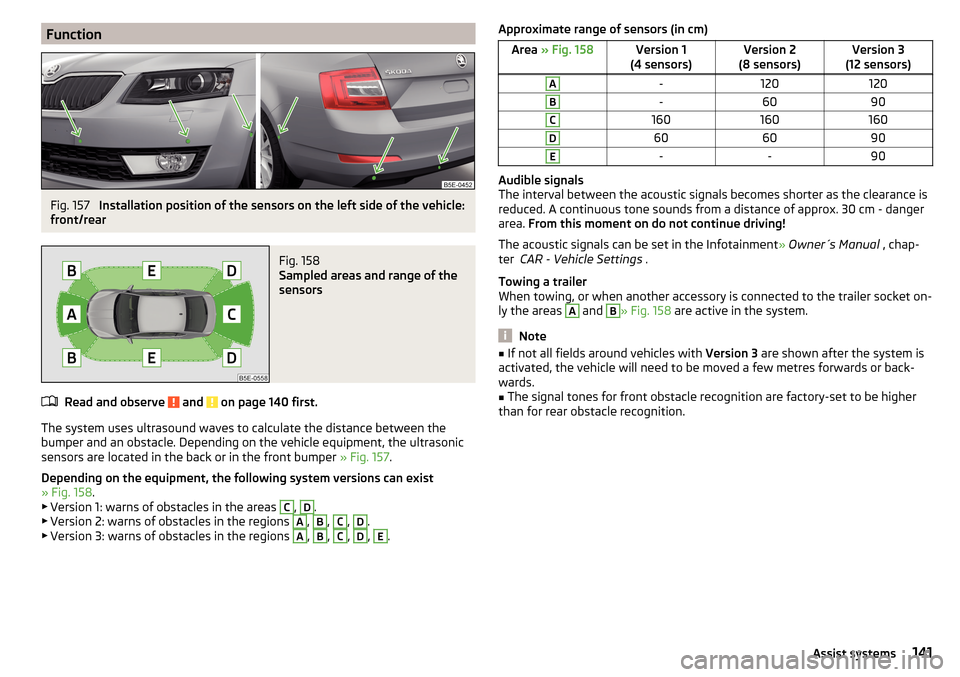
FunctionFig. 157
Installation position of the sensors on the left side of the vehicle:
front/rear
Fig. 158
Sampled areas and range of the
sensors
Read and observe and on page 140 first.
The system uses ultrasound waves to calculate the distance between the
bumper and an obstacle. Depending on the vehicle equipment, the ultrasonic
sensors are located in the back or in the front bumper » Fig. 157.
Depending on the equipment, the following system versions can exist
» Fig. 158 .
▶ Version 1: warns of obstacles in the areas
C
,
D
.
▶ Version 2: warns of obstacles in the regions
A
,
B
,
C
,
D
.
▶ Version 3: warns of obstacles in the regions
A
,
B
,
C
,
D
,
E
.
Approximate range of sensors (in cm)Area » Fig. 158Version 1
(4 sensors)Version 2
(8 sensors)Version 3
(12 sensors)A-120120B-6090C160160160D606090E--90
Audible signals
The interval between the acoustic signals becomes shorter as the clearance is
reduced. A continuous tone sounds from a distance of approx. 30 cm - danger
area. From this moment on do not continue driving!
The acoustic signals can be set in the Infotainment » Owner´s Manual , chap-
ter CAR - Vehicle Settings .
Towing a trailer
When towing, or when another accessory is connected to the trailer socket on-
ly the areas
A
and
B
» Fig. 158 are active in the system.
Note
■
If not all fields around vehicles with Version 3 are shown after the system is
activated, the vehicle will need to be moved a few metres forwards or back-
wards.■
The signal tones for front obstacle recognition are factory-set to be higher
than for rear obstacle recognition.
141Assist systems
Page 145 of 268

Automatic system activation when moving forwardFig. 161
Infotainment display: Display
with automatic activation
Read and observe and on page 140 first.
The automatic system activation occurs when moving forward at a speed be- low 10 km / h when the vehicle approaches an obstacle.
After activation, the following is shown in the left pane of the Infotainment
display » Fig. 161 .
Acoustic signals are sounded as of a distance from the obstacle of around
50 cm.
The automatic display can be enabled or disabled in the Infotainment » Owner
´s Manual Infotainment , chapter CAR - vehicle settings .
Rear View Camera
Introduction
This chapter contains information on the following subjects:
Operation
143
Guidelines and function keys
144
The rear view camera (hereinafter referred to as system) helps the driver when
parking and manoeuvring by displaying the area behind the vehicle in the Info-
tainment display (hereinafter referred to as display).
WARNING■ The general information relating to the use of assistance systems must
be observed » page 135, in section Introduction .■
Make sure that the camera lens is not dirty or covered, otherwise the sys-
tem function can be significantly impaired. For information on cleaning
» page 185 , Camera lens
CAUTION
■
The camera lens distorts and enlarges the field of view of the difference in
eye sight. The display is therefore only of limited use for estimating distances
to following vehicles.■
Some items, such as thin columns, chain link fences or lattice may not be
represented adequately in terms of display resolution.
■
It is only a two-dimensional display. Therefore, protruding objects or roadway
depressions, for example, may not be recognised due to lack of space depth.
■
In a crash or damage the vehicle's rear camera can possibly deviate from the
correct position. If this is the case, have the sensor checked by a specialist ga-
rage.
Operation
Fig. 162
Position of the camera / Monitored area
Read and observe
and on page 143 first.
The camera for capturing the area behind the vehicle is in the grip of the boot lid » Fig. 162 .
Supervised area » Fig. 162
Detection range of the camera.
Area outside the detection range of the camera.
AB143Assist systems
Page 147 of 268
The state in which the steering wheel is operated by the system, is referred to
as parking operation.
The Park Assist is an extension of the parking aid » page 140 and operates on
the basis of data collected by the ultrasonic sensors.
For this reason, the chapter on the parking aid is to be read carefully and the safety notes are to be observed.WARNING■ The general information relating to the use of assistance systems must
be observed » page 135, in section Introduction .■
During the parking process, the system automatically performs rapid
steering movements. While it is doing so, do not place your hands between
the steering wheel – risk of injury!
■
During a parking manoeuvre on loose or slippery surfaces (gravel, snow,
ice, etc.) you may stray from the calculated road. Therefore, do not use the
system in such situations.
CAUTION
The correct evaluation of the parking space and the parking procedure de-
pends on the circumference of the wheels on the vehicle.■
The system only works correctly if the vehicle is fitted with the wheel size
approved by the manufacturer.
■
Abstain from using the system when the vehicle is fitted with snow chains or
a temporary spare wheel.
■
If wheels other than those approved by the manufacturer are mounted, the
resulting position of the vehicle in the parking space can differ slightly. This
can be avoided by readjusting the system at a specialist garage.
CAUTION
If other vehicles are parked behind the kerb or on it, the system can also guide
your vehicle beyond the kerb or onto it. Ensure that the wheels or the wheel
rims of your vehicle are not damaged and if necessary intervene in time.
Note
■ We recommend performing the parking at a safe speed to about 5 km / h.■The driver can stop the parking process at any time by pressing the symbol
key
» Fig. 164 on page 146 or by a driver steering intervention.Functioning
Read and observe
and on page 145 first.
The system support is provided in the following manner.▶ While the parking space search is going on, a measurement and evaluation of
the parking space size is completed.
▶ Suitable parking spaces are shown in the display of the instrument cluster
(hereinafter only in the display).
▶ The display shows instructions and information before the start and during
the parking.
▶ The road way is calculated that the vehicle uses during the parking.
▶ The front wheels are automatically rotated during the parking.
Conditions for the system function
The system can look for a parking space only if the following basic conditions
are met.
The system is activated.
The vehicle speed is less than 40 km / h (parallel parking).
The vehicle speed is less than 20 km / h (transverse parking). The distance to a number of parked vehicles is approximately 0.5 - 1.5 m.
The TCS is activated » page 135, Braking and stabilisation systems .
The system can only carry out the parking if the following basic conditions are
met.
The vehicle is travelling less than about 7 km/h.
The parking procedure takes less than 6 minutes.
There is no driver intervention in the automatic steering operation.
Activation/deactivation
The system can be enabled or disabled by pressing the symbol key
» Fig. 164
on page 146 -
.
When the system is activated, the symbol illuminates.
145Assist systems
Page 152 of 268
NoteDuring control, speed can be increased by pressing the accelerator pedal. Re-
leasing the accelerator pedal will cause the speed to drop again to the set
speed.
Adaptive Cruise Control (ACC)
Introduction
This chapter contains information on the following subjects:
Operation
150
Automatic stop-start
151
Operation Overview
152
Start control
152
Stop/resume control
152
Set/change the desired speed
153
Set the clearance level
153
Special driving conditions
154
Information messages
155
The automatic distance control (hereinafter referred to as ACC) maintains the
set speed or the distance to the vehicle ahead without the accelerator or
brake pedal being pressed.
The front of the vehicle and the distance to the vehicle ahead is monitored by
a radar sensor » page 135.
The state in which the ACC maintains the speed or the proximity is described
as control from here on.
WARNING■
The general information relating to the use of assistance systems must
be observed » page 135, in section Introduction .■
The driver must always be ready to take over steering of the vehicle him-
self (accelerate or brake).
■
The ACC does not react when approaching a stationary obstacle, such as
traffic jams, vehicle breakdowns or vehicles waiting at a traffic light.
■
The ACC does not respond to crossing or oncoming objects.
■
If the ACC does not decelerate fast enough, immediately apply the vehi-
cle's foot brake.
WARNINGFor safety reasons, do not use the ACC under the following conditions.■When driving in turning lanes, motorway exits or construction sites, to
avoid an unwanted acceleration to the stored speed.■
When visibility is poor, (e.g. fog, heavy rain, thick snowfall).
■
When road conditions are poor (e.g. ice, slippery road, gravel, dirt road).
■
When driving around “sharp” bends.
■
When riding on a steep gradient / high slope.
■
When driving through places where metal objects (such as metal build-
ings, railroad tracks, etc.) can be found.
■
When driving through very divided and enclosed spaces (such as large-ca-
pacity garages, car ferries, tunnels and the like.).
Note
■ The ACC is designed primarily for use on motorways.■The ACC reduces the speed by automatically releasing the accelerator or by
means of a braking procedure as appropriate. If the brakes are used for an au-
tomatic speed reduction at any moments, then the brake light illuminates.■
In case of failure of more than one brake light on the vehicle or on the con-
nected trailer, the ACC becomes unavailable.
■
The control automatically cancels the engagement of the brake supportive
assistance systems (e.g. ESC) or when the maximum permitted engine speed is
exceeded.
Operation
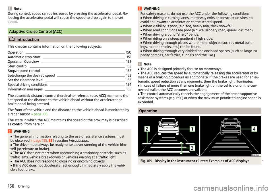
Fig. 169
Display in the instrument cluster: Examples of ACC displays
150Driving
Page 153 of 268
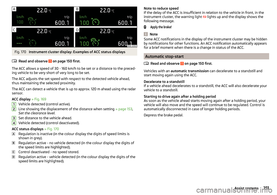
Fig. 170
Instrument cluster display: Examples of ACC status displays
Read and observe
on page 150 first.
The ACC allows a speed of 30 - 160 km/h to be set or a distance to the preced- ing vehicle to be very short of very long to be set.
The ACC adjusts the set speed with respect to the detected vehicle ahead,
thus maintaining the selected proximity.
The ACC can detect a vehicle that is up to approx. 120 m ahead using the radar sensor.
ACC display » Fig. 169
Vehicle detected (control active).
Line showing the displacement of the distance when setting » page 153,
Set the clearance level .
Set distance to the vehicle ahead.
Vehicle detected (control deactivated).
ACC status displays » Fig. 170
Regulation is inactive (in the colour display the digits of speed limits is
shown in grey).
Regulation active - no vehicle detected (in the colour display the digits of
the speed limits are highlighted).
Control deactivated - no speed stored.
Regulation active - vehicle detected (in the colour display the digits of the
speed limits are highlighted).
1234Note to reduce speed
If the delay of the ACC is insufficient in relation to the vehicle in front, in the
instrument cluster, the warning light
lights up and the display shows the
following message.Apply the brake!
Note
Some ACC notifications in the display of the instrument cluster may be hidden
by notifications for other functions. An ACC notification automatically appears
for a brief moment when there is a change in status of the ACC.
Automatic stop-start
Read and observe
on page 150 first.
Vehicles with an automatic transmission can decelerate to a standstill and
start moving again using the ACC.
Decelerate to a standstill
If a vehicle ahead decelerates to a standstill, the ACC will also decelerate your
vehicle to a standstill.
Starting to drive again after a holding period
As soon as the vehicle ahead starts moving again after a holding period, your
vehicle will also move and the speed will continue to be regulated. Control is
automatically disconnected in case of longer holding periods.
Depress the brake pedal.
151Assist systems
Page 156 of 268
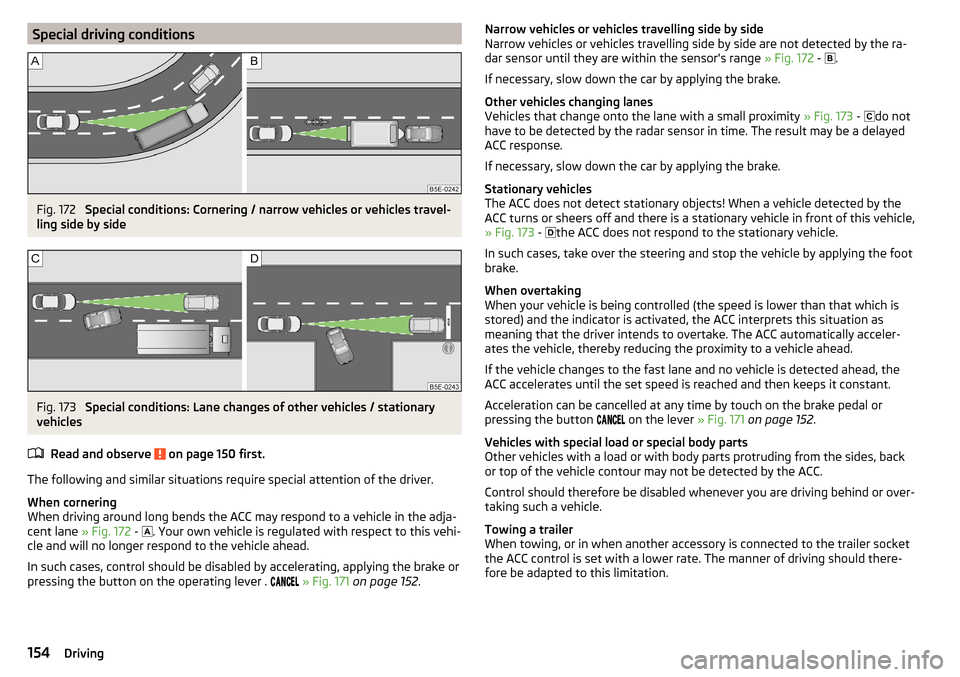
Special driving conditionsFig. 172
Special conditions: Cornering / narrow vehicles or vehicles travel-
ling side by side
Fig. 173
Special conditions: Lane changes of other vehicles / stationary
vehicles
Read and observe
on page 150 first.
The following and similar situations require special attention of the driver.
When cornering
When driving around long bends the ACC may respond to a vehicle in the adja-
cent lane » Fig. 172 -
. Your own vehicle is regulated with respect to this vehi-
cle and will no longer respond to the vehicle ahead.
In such cases, control should be disabled by accelerating, applying the brake or
pressing the button on the operating lever .
» Fig. 171 on page 152 .
Narrow vehicles or vehicles travelling side by side
Narrow vehicles or vehicles travelling side by side are not detected by the ra-
dar sensor until they are within the sensor's range » Fig. 172 -
.
If necessary, slow down the car by applying the brake.
Other vehicles changing lanes
Vehicles that change onto the lane with a small proximity » Fig. 173 -
do not
have to be detected by the radar sensor in time. The result may be a delayed
ACC response.
If necessary, slow down the car by applying the brake.
Stationary vehicles
The ACC does not detect stationary objects! When a vehicle detected by the
ACC turns or sheers off and there is a stationary vehicle in front of this vehicle,
» Fig. 173 -
the ACC does not respond to the stationary vehicle.
In such cases, take over the steering and stop the vehicle by applying the foot
brake.
When overtaking
When your vehicle is being controlled (the speed is lower than that which is
stored) and the indicator is activated, the ACC interprets this situation as
meaning that the driver intends to overtake. The ACC automatically acceler-
ates the vehicle, thereby reducing the proximity to a vehicle ahead.
If the vehicle changes to the fast lane and no vehicle is detected ahead, the
ACC accelerates until the set speed is reached and then keeps it constant.
Acceleration can be cancelled at any time by touch on the brake pedal or
pressing the button on the lever
» Fig. 171 on page 152 .
Vehicles with special load or special body parts
Other vehicles with a load or with body parts protruding from the sides, back
or top of the vehicle contour may not be detected by the ACC.
Control should therefore be disabled whenever you are driving behind or over-
taking such a vehicle.
Towing a trailer
When towing, or in when another accessory is connected to the trailer socket
the ACC control is set with a lower rate. The manner of driving should there-
fore be adapted to this limitation.154Driving