weight SKODA OCTAVIA 2015 3.G / (5E) User Guide
[x] Cancel search | Manufacturer: SKODA, Model Year: 2015, Model line: OCTAVIA, Model: SKODA OCTAVIA 2015 3.G / (5E)Pages: 268, PDF Size: 37.54 MB
Page 134 of 268
›START STOP deactivate
» page 126, Manually deactivating/activating the
system .›
Fully depress and hold the brake pedal with your left foot.
›
Fully depress the accelerator pedal with your right foot.
›
Release the brake pedal.
The vehicle starts off with maximum acceleration.
›
Reactivate the TCS and START-STOP when the desired speed has been
reached.
WARNINGRapid acceleration, particularly on slippery roads, can lead to loss of control
of the vehicle – risk of accident!
Running-in and economical driving
Introduction
This chapter contains information on the following subjects:
Running-in
132
Tips for economical driving
132
DriveGreen function
133
The fuel consumption, degree of pollution and vehicle wear depend on driving
style, road condition, weather conditions and the like.
Running-in
Driving in the engine
The engine has to be run in during the first 1500 kilometres. During this period,
the driving style decides on the quality of the driving-in process.
During the first 1 000 km we recommend not driving faster than 3/4 of the
maximum permissible engine speed, not to drive at full throttle and to dis-
pense with the trailer.
In the area of 1,000 to 1,500 kilometres the engine load can be increased up
to the maximum permitted engine speed.
New tyres
New tyres have to be “run in” since they do not offer optimal grip at first.
Drive especially carefully for the first 500 km or so.
New brake pads
New brake pads have to first “grind in” because these do not initially have the
best possible braking effect.
Drive especially carefully for the first 200 km or so.
Tips for economical driving
To achieve the lowest possible fuel consumption, the following instructions
must be observed.
Looking ahead when driving
Avoid unnecessary acceleration and braking.
Switch in an energy saving and timely manner Observe the recommended gear » page 41.
Avoid full throttle and high speeds
Fuel consumption can be reduced by half if only three-quarters of the possible
top speed of your vehicle is used.
Reducing idling
If the vehicle is fitted with the START STOP system there is an automatic re-
duction of the idling. If the engine is stopped on vehicles without START-STOP
system, such as when waiting in a traffic jam, the fuel economy is already
greater after 30 - 40 s than the fuel quantity which is required for engine re-
start.
Avoid short distances
When driving a short distance of less than about 4 km, the engine cannot
reach its operating temperature. As long as the engine has not reached oper-
ating temperature, the fuel consumption is significantly higher than with the
engine hot.
Pay attention to the correct tyre inflation pressure being maintained
Further information » page 205.
Avoid unnecessary ballast
Per 100 kg of weight, consumption increases by about 0.3 l/100 km. At a speed
of 100 - 120 km/h, a vehicle fitted with a roof rack cross member without a load
will use about 10 % more fuel than normal due to the increased aerodynamic
drag.
Saving electricity
Only turn on electrical consumers (e.g. seat, window and mirror heating and
the like) for as long as necessary.
132Driving
Page 169 of 268
Hitch and trailer
Hitch
Introduction
This chapter contains information on the following subjects:
Description
167
Adjusting the ready position
168
Correctly adjusted ready position
168
Assembling the bar ball – Step 1
169
Assembling the bar ball – Step 2
169
Check proper fitting
170
Removing the bar ball – Step 1
170
Removing the bar ball – Step 2
171
Mount accessories
171
The maximum trailer drawbar load is 75 kg.
For vehicles with all-wheel drive, the maximum trailer nose weight is 80 kg.
With G-TEC-vehicles, the maximum trailer drawbar load is 56 kg .
The draw bar load information on the type plate of the towing device is merely
a test value for the towing device. The vehicle-specific information is detailed
in the vehicle documents.
WARNING■ Before each time you make a journey when using the ball rod, check that
it is seated correctly and is secured in the mounting recess.■
Do not use the ball rod if it is not correctly inserted into the mounting re-
cess and secured.
■
Do not use the towing hitch if it is damaged or if there are parts missing.
■
Do not perform any modifications or changes to the towing device.
■
Keep the mounting recess of the towing device clean at all times. Such
dirt prevents the ball rod from being attached securely!
CAUTION
■ Take care when using the ball rod - there is a risk of paint damage to the
bumper.■
When the ball rod is removed always place the cover onto the mounting re-
cess - there is a danger of soiling the mounting recess.
Note■ Operation and maintenance of the tow hitch » page 186.■The towing vehicle by means of the detachable ball rod » page 222.■
If the towing device is removed completely, it must be replaced with the
original reinforcement of the rear bumper which is part of the mount for the
towing eye.
Description
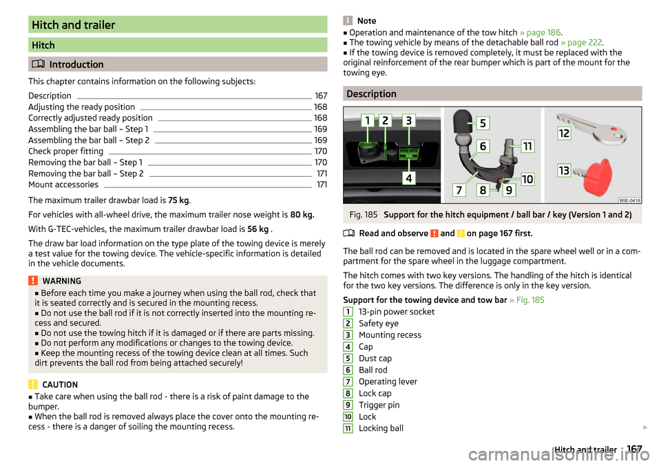
Fig. 185
Support for the hitch equipment / ball bar / key (Version 1 and 2)
Read and observe
and on page 167 first.
The ball rod can be removed and is located in the spare wheel well or in a com-
partment for the spare wheel in the luggage compartment.
The hitch comes with two key versions. The handling of the hitch is identical
for the two key versions. The difference is only in the key version.
Support for the towing device and tow bar » Fig. 185
13-pin power socket
Safety eye
Mounting recess
Cap
Dust cap
Ball rod
Operating lever
Lock cap
Trigger pin
Lock
Locking ball
1234567891011167Hitch and trailer
Page 173 of 268
WARNINGNever remove the tow bar while the trailer is still coupled.
Note
We recommend putting the protective cover onto the ball head before remov-
ing the tow bar.
Removing the bar ball – Step 2
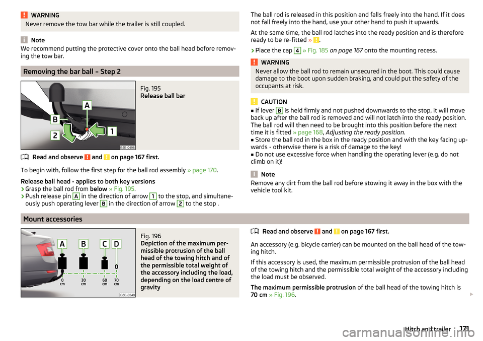
Fig. 195
Release ball bar
Read and observe and on page 167 first.
To begin with, follow the first step for the ball rod assembly » page 170.
Release ball head - applies to both key versions
›
Grasp the ball rod from below » Fig. 195 .
›
Push release pin
A
in the direction of arrow
1
to the stop, and simultane-
ously push operating lever
B
in the direction of arrow
2
to the stop .
The ball rod is released in this position and falls freely into the hand. If it does
not fall freely into the hand, use your other hand to push it upwards.
At the same time, the ball rod latches into the ready position and is therefore
ready to be re-fitted »
.
›
Place the cap
4
» Fig. 185 on page 167 onto the mounting recess.
WARNINGNever allow the ball rod to remain unsecured in the boot. This could cause
damage to the boot upon sudden braking, and could put the safety of the
occupants at risk.
CAUTION
■ If lever B is held firmly and not pushed downwards to the stop, it will move
back up after the ball rod is removed and will not latch into the ready position.
The ball rod will then need to be brought into this position before the next
time it is fitted » page 168, Adjusting the ready position .■
Store the ball rod in the box in the ready position and with the key facing up-
wards - otherwise there is a risk of damage to the key!
■
Do not use excessive force when handling the operating lever (e.g. do not
climb on it)!
Note
Remove any dirt from the ball rod before stowing it away in the box with the
vehicle tool kit.
Mount accessories
Fig. 196
Depiction of the maximum per-
missible protrusion of the ball
head of the towing hitch and of
the permissible total weight of
the accessory including the load,
depending on the load centre of
gravity
Read and observe and on page 167 first.
An accessory (e.g. bicycle carrier) can be mounted on the ball head of the tow-
ing hitch.
If this accessory is used, the maximum permissible protrusion of the ball head
of the towing hitch and the permissible total weight of the accessory including
the load must be observed.
The maximum permissible protrusion of the ball head of the towing hitch is
70 cm » Fig. 196 .
171Hitch and trailer
Page 174 of 268

The total permitted weight of the accessory including load changes with in-
creasing distance of the load centre of gravity from the ball head of the towing
hitch.Distance of the load
centre of gravity from the ball headPermissible total weight of the accessory, including load» Fig. 196Vehicles with front-wheel driveVehicles with four-wheel driveG-TEC vehicles0 cmA75 kg75 kg56 kg30 cmB75 kg75 kg56 kg60 cmC35 kg35 kg28 kg70 cmD0 kg0 kg0 kgWARNING■Never exceed the permissible gross weight of the accessory including
load - there is a risk of damaging the towing device.■
Never exceed the permissible protrusion of the ball head including towing
device - there is a risk of damaging the towing device.
Note
We recommend that you use accessories from ŠKODA Original Accessories.
Trailer
Introduction
This chapter contains information on the following subjects:
Attaching and detaching trailers
172
Loading a trailer
173
Trailer load
173
Trailer operation
176
Anti-theft alarm system
177
The trailer can be hitched to the ball head of the towing device.
Attaching and detaching trailersFig. 197
Swivel out the 13-pin power
socket, safety eyelet
Connect and disconnect
›
Fit the ball rod.
›
Grip the 13-pin socket at point
A
and swing out in the direction of the arrow
» Fig. 197 .
›
Lift off protective cap
5
» Fig. 185 on page 167 .
›
Place the trailer onto the ball head.
›
Plug the trailer cable into 13-pin socket
A
» Fig. 197 .
If the trailer that is to be towed has a 7-pin connector, you can use a suitable
adapter from ŠKODA Original Accessories.
›
Hook the breakaway cable of the trailer to the security eyelet
B
.
The breakaway cable of the trailer must sag in all trailer positions relative to
the vehicle (sharp curves, reversing and the like).
Uncoupling takes place in reverse order.
172Driving
Page 175 of 268
Exterior mirrors
You should have additional exterior mirrors fitted if you are not able to see the
traffic behind the trailer with the standard rear-view mirrors.
Headlights
The front of the vehicle may lift up when a trailer is being towed and the head-
lights may dazzle other road users.
Adjust the headlights using the headlight beam control » page 68, Operating
the lights 1)
.
Power to the trailer power grid
For the electrical connection between the vehicle and trailer, the trailer's pow-
er supply is provided by the vehicle.
The power supply works with ignition on or off.
With the ignition off, the battery of the towing vehicle is discharged by activa-
ted consumers.
At low charge state of the vehicle battery power to the trailer is interrupted.WARNING■ Improperly connected trailer electrical installations may cause accidents
or serious injury due to electric shock.■
Work on the electrical system must only be carried out by specialist ga-
rages.
■
Never directly connect the trailer's electrical system with the electrical
connections for the tail lights or other current sources.
WARNING (Continued)■ After attaching the trailer and connecting the power socket, check that
the rear lights on the trailer are working correctly.■
Never use the safety eye to tow a vehicle!
CAUTION
Improperly connected trailer electrical installations may cause malfunction of
the entire vehicle electronics.
Note
■ The total power consumption of all the connected consumers on the trailer
must not exceed 350 watts.■
Coat the ball head of the towing device with a suitable grease whenever
necessary.
Loading a trailer
Distribution of the cargo
Distribute the cargo in the trailer in such a way that heavy items are located as
close to the trailer axle as possible. Secure the items from slipping.
The distribution of the weight is very poor if your vehicle is unladen and the
trailer is laden. Drive at a particularly low speed if you cannot avoid driving
with this combination.
Tyre pressure
Correct the tyre inflation pressure on the vehicle for a “full load” » page 205.
WARNINGSliding cargo can significantly adversely affect stability and driving safety -
risk of accident!
Trailer load
The permissible trailer load must not be exceeded under any circumstances. 1)
Applies to vehicles with xenon headlights.
173Hitch and trailer
Page 178 of 268
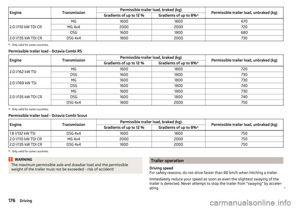
EngineTransmissionPermissible trailer load, braked (kg)Permissible trailer load, unbraked (kg)Gradients of up to 12 %Gradients of up to 8%a)
2.0 l/110 kW TDI CR
MG16001800670MG 4x420002000720DSG160018006802.0 l/135 kW TDI CRDSG 4x418002000730a)
Only valid for some countries.
Permissible trailer load - Octavia Combi RS
EngineTransmissionPermissible trailer load, braked (kg)Permissible trailer load, unbraked (kg)Gradients of up to 12 %Gradients of up to 8% a)2.0 l/162 kW TSIMG16001800720DSG160018007302.0 l/169 kW TSIMG16001800730DSG16001800740
2.0 l/135 kW TDI CR
MG16001800730DSG16001800740DSG 4x418002000750a)
Only valid for some countries.
Permissible trailer load - Octavia Combi Scout
EngineTransmissionPermissible trailer load, braked (kg)Permissible trailer load, unbraked (kg)Gradients of up to 12 %Gradients of up to 8% a)1.8 l/132 kW TSIDSG 4x4160018007502.0 l/110 kW TDI CRMG 4x4200020007502.0 l/135 kW TDI CRDSG 4x418002000750a)
Only valid for some countries.
WARNINGThe maximum permissible axle and drawbar load and the permissible
weight of the trailer must not be exceeded - risk of accident!Trailer operation
Driving speed
For safety reasons, do not drive faster than 80 km/h when hitching a trailer.
Immediately reduce your speed as soon as even the slightest swaying of the
trailer is detected. Never attempt to stop the trailer from “swaying” by acceler-
ating. 176Driving
Page 238 of 268
Technical data
Technical data
Basic vehicle data
Introduction
This chapter contains information on the following subjects:
Vehicle characteristics
236
Operating weight
237
Payload
238
Measurement of fuel consumption and CO 2 emissions according to ECE
Regulations and EU Directives
239
Dimensions - Octavia
240
Dimensions - Octavia estate
241
Track gauge front/rear
242
Departure angle
243
The details given in the vehicle's technical documentation always take prece-
dence over the details in the Owner's Manual.
The listed performance values were determined without performance-reduc- ing equipment, e.g. air conditioning system.
The values given have been determined in accordance with regulations and in
conditions prescribed by legal or technical provisions for determining the oper-
ating and technical data of vehicles.
The values listed are for the basic model without optional equipment.
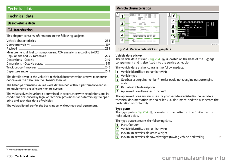
Vehicle characteristicsFig. 254
Vehicle data sticker/type plate
Vehicle data sticker
The vehicle data sticker » Fig. 254 -
is located on the base of the luggage
compartment and is also fixed into the service schedule.
The vehicle data sticker contains the following data. Vehicle identification number (VIN)
Vehicle type
Gearbox code/paint number/interior equipment/engine output/engine code
Partial vehicle description
Approved tyre diameter in inches 1)
The approved tyres and rim sizes for your vehicle are listed in the vehicle's
technical documentation (the so called COC document) and this also states the
declaration of conformity.
Type plate
The type plate » Fig. 254 -
is located at the bottom of the B-pillar on the
right driver's side.
The type plate contains the following data. Manufacturer
Vehicle identification number (VIN)
Maximum permissible gross weight
Maximum permissible towed weight (towing vehicle and trailer)
1234567891)
Only valid for some countries.
236Technical data
Page 239 of 268
Maximum permissible front axle load
Maximum permissible rear axle load
Vehicle identification number (VIN)
The vehicle identification number - VIN (vehicle body number) is stamped into
the engine compartment on the right hand suspension strut dome. This num-
ber is also located on a sign on the lower left hand edge below the windscreen
(together with a VIN bar code), and on the type plate.
The VIN number can also be displayed in the Infotainment » Owner´s Manual
Infotainment , chapter CAR - vehicle settings .
Engine number
The engine number (three-digit identifier and serial number) is stamped on the
engine block.
Supplementary Information (applies to Russia)
The full type approval number of the means of transport is indicated in the
registration documents, field 17.
Maximum permissible trailer weight
The listed maximum allowable trailer weight is only valid for altitudes up to
1000 m above sea level.
The engine output falls as the height increases, as does the ability to climb.
Therefore, for every additional 1000 m in height (or part), the maximum per-
missible towed weight must be reduced by 10%.
The towed weight is made up of the actual weights of the loaded towing vehi-
cle and the loaded trailer.WARNINGDo not exceed the specified maximum permissible weights – risk of acci-
dent and damage!
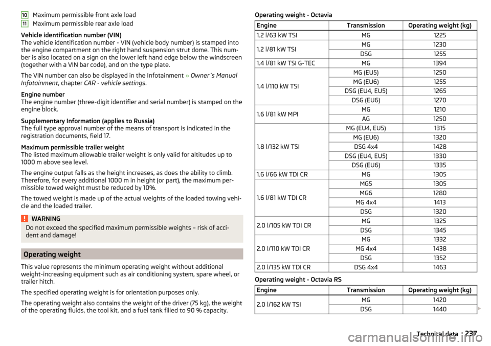
Operating weight
This value represents the minimum operating weight without additional
weight-increasing equipment such as air conditioning system, spare wheel, or trailer hitch.
The specified operating weight is for orientation purposes only.
The operating weight also contains the weight of the driver (75 kg), the weight
of the operating fluids, the tool kit, and a fuel tank filled to 90 % capacity.
1011Operating weight - OctaviaEngineTransmissionOperating weight (kg)1.2 l/63 kW TSIMG12251.2 l/81 kW TSIMG1230DSG12551.4 l/81 kW TSI G-TECMG1394
1.4 l/110 kW TSI
MG (EU5)1250MG (EU6)1255DSG (EU4, EU5)1265DSG (EU6)12701.6 l/81 kW MPIMG1210AG1250
1.8 l/132 kW TSI
MG (EU4, EU5)1315MG (EU6)1320DSG 4x41428DSG (EU4, EU5)1330DSG (EU6)13351.6 l/66 kW TDI CRMG1305
1.6 l/81 kW TDI CR
MG51305MG61280MG 4x41413DSG13202.0 l/105 kW TDI CRMG1325DSG1345
2.0 l/110 kW TDI CR
MG1332MG 4x41438DSG13522.0 l/135 kW TDI CRDSG 4x41463
Operating weight - Octavia RS
EngineTransmissionOperating weight (kg)2.0 l/162 kW TSIMG1420DSG1440 237Technical data
Page 240 of 268
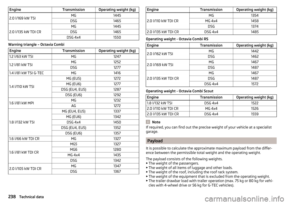
EngineTransmissionOperating weight (kg)2.0 l/169 kW TSIMG1445DSG1465
2.0 l/135 kW TDI CR
MG1445DSG1465DSG 4x41550
Warning triangle – Octavia Combi
EngineTransmissionOperating weight (kg)1.2 l/63 kW TSIMG12471.2 l/81 kW TSIMG1252DSG12771.4 l/81 kW TSI G-TECMG1416
1.4 l/110 kW TSI
MG (EU5)1272MG (EU6)1277DSG (EU4, EU5)1287DSG (EU6)12921.6 l/81 kW MPIMG1232AG1272
1.8 l/132 kW TSI
MG (EU4, EU5)1337MG (EU6)1342DSG 4x41450DSG (EU4, EU5)1352DSG (EU6)13571.6 l/66 kW TDI CRMG1327
1.6 l/81 kW TDI CR
MG51327MG61280MG 4x41435DSG13422.0 l/105 kW TDI CRMG1347DSG1367EngineTransmissionOperating weight (kg)
2.0 l/110 kW TDI CR
MG1354MG 4x41458DSG13742.0 l/135 kW TDI CRDSG 4x41485
Operating weight - Octavia Combi RS
EngineTransmissionOperating weight (kg)2.0 l/162 kW TSIMG1442DSG14622.0 l/169 kW TSIMG1467DSG1487
2.0 l/135 kW TDI CR
MG1467DSG1487DSG 4x41572
Operating weight - Octavia Combi Scout
EngineTransmissionOperating weight (kg)1.8 l/132 kW TSIDSG 4x415222.0 l/110 kW TDI CRMG 4x415262.0 l/135 kW TDI CRDSG 4x41559
Note
If required, you can find out the precise weight of your vehicle at a specialist
garage.
Payload
It is possible to calculate the approximate maximum payload from the differ-
ence between the permissible total weight and the operating weight.
The payload consists of the following weights.
▶ The weight of the passengers.
▶ The weight of all items of luggage and other loads.
▶ The weight of the roof, including the roof rack system.
▶ The weight of the equipment that is excluded from the operating weight.
▶ The trailer drawbar load with trailer operation (max. 75 kg or 80 kg for vehi-
cles with 4-wheel drive or 56 kg for G-TEC vehicles).
238Technical data
Page 241 of 268

Measurement of fuel consumption and CO2 emissions according to
ECE Regulations and EU Directives
The data on fuel consumption and CO 2 emissions were not available at the
time of going to press.
The data on fuel consumption and CO 2 emissions are given on the ŠKODA
websites or in the sales and technical vehicle documentation.
The measurement of the intra-urban cycle begins with a cold start of the en-
gine. Afterwards urban driving is simulated.
In the extra-urban driving cycle, the vehicle is accelerated and decelerated in
all gears, corresponding to daily routine driving conditions. The driving speed
varies between 0 and 120 km/h.
The calculation of the combined fuel consumption considers a weighting of
about 37 % for the intra-urban cycle and 63 % for the extra-urban cycle.
Note
■ The fuel consumption and emission levels given on the ŠKODA websites or in
the commercial and technical vehicle documentation have been established in
accordance with rules and under conditions that are set out by legal or techni-
cal rules for the determination of operational and technical data of motor vehi-
cles.■
Depending on the extent of the equipment, the driving style, traffic condi-
tions, weather influences and vehicle condition, consumption values can in
practice result in fuel economy figures in the use of the vehicle that differ from
the fuel consumption values listed on the ŠKODA websites or in the commer-
cial and technical vehicle documentation.
239Technical data