warning SKODA OCTAVIA 2016 3.G / (5E) Owner's Manual
[x] Cancel search | Manufacturer: SKODA, Model Year: 2016, Model line: OCTAVIA, Model: SKODA OCTAVIA 2016 3.G / (5E)Pages: 324, PDF Size: 48.85 MB
Page 229 of 324
WARNING■The general information relating to the use of assistance systems must
be observed » page 199, in section Introduction .■
Vertical traffic signs must always take precedence over the traffic signs
shown in the display. The driver is always responsible for correctly assess-
ing the traffic situation.
■
On the system side, only a traffic sign display is undertaken, neither a
warning when limit is exceeded or driving speed adjustment is undertaken!
■
Speed specifications in the displayed road signs refer to the customary
speed units. For example, the view
in the display can therefore refer to
km / h or mph, specific to the country.
WARNINGThe traffic signs may not be displayed or displayed incorrectly in the system
e.g. in the following situations.■
When visibility is poor, (e.g. fog, heavy rain, thick snowfall).
■
The sensor is blinded by the sun or oncoming traffic.
■
The field of view of the sensor is limited by an obstacle or a preceding ve-
hicle.
■
Travelling at high speed.
■
The traffic signs are covered (e.g. by trees, snow or dirt).
■
The traffic signs are not standard (round with a red border) or are dam-
aged.
■
The traffic signs are attached to flashing neon signs.
■
The traffic signs were changed (the navigation data are out of date).
Note
The system is only available in some countries.
Settings in Infotainment
Read and observe
on page 227 first.
›
Press the button, then tap on the function surface
→
Driver assistance
.
■ Dynamic Road Sign Display - Settings for the Dynamic Road Sign Display
■
Show in instrument cluster
- Activation/deactivation of the additional traffic
signs in the display of the instrument cluster
■
Speed warning::
» page 221 - Setting a warning when exceeding the speed
limit
■ Trailer recognition
■Show road signs relevant to trailers
- Activating / deactivating the display of road
signs relevant to trailers
■
Use for route calculation
- Activation / deactivation taking trailers in account for
route calculation in navigation
Operation
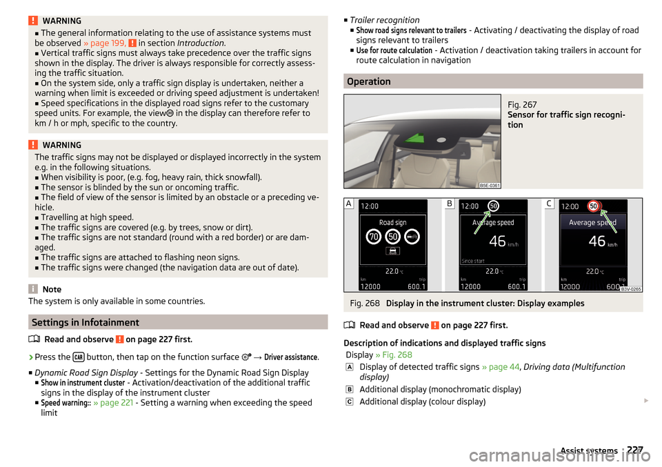
Fig. 267
Sensor for traffic sign recogni-
tion
Fig. 268
Display in the instrument cluster: Display examples
Read and observe
on page 227 first.
Description of indications and displayed traffic signs
Display » Fig. 268Display of detected traffic signs » page 44, Driving data (Multifunction
display)Additional display (monochromatic display)Additional display (colour display) 227Assist systems
Page 231 of 324
WARNING■The general information relating to the use of assistance systems must
be observed » page 199, in section Introduction .■
For the driving ability is always the driver's responsibility. Never drive if
you feel tired.
■
The system may not detect all cases where a break is needed.
■
Therefore, take regular, sufficient breaks during long trips.
■
There will be no system warning during the so-called micro-sleep.
Note
■ In some situations, the system may evaluate the driving incorrectly and thus
mistakenly recommend a break (e.g. sporty driving, adverse weather condi-
tions or poor road conditions).■
The system is designed primarily for use on motorways.
Tyre pressure monitoring
Introduction
This chapter contains information on the following subjects:
Storing the tyre pressure values and Infotainment display
229
The tyre pressure monitoring function (hereinafter referred to as the system)
monitors the tyre pressure while driving.
If the tyre inflation pressure changes, the warning light
lights up in the in-
strument cluster and an audible signal sounds » page 35.
The system can only function properly if the tyres have the prescribed inflation
pressure and these pressure values are stored in the system.
The tyre pressure values are always stored in the system if one of the fol-
lowing events occurs.
▶ Change of tyre inflation pressure.
▶ Change one or more wheels.
▶ Change in position of a wheel on the vehicle.
▶ The warning light
lights up in the instrument cluster.
WARNING■
The general information relating to the use of assistance systems must
be observed » page 199, in section Introduction .■
Having the correct tyre inflation pressure is always the driver's responsi-
bility. Tyre inflation pressure must be checked regularly » page 261.
■
The system cannot warn in case of very rapid tyre inflation pressure loss,
e.g. in case of sudden tyre damage.
■
Before storing the pressure values, the tyres must be inflated to the
specified inflation pressure » page 261. If incorrect pressure values are
saved, the system may also not issue a warning even if the tyre inflation
pressure is too low.
CAUTION
To ensure proper system function, the tire pressure values must be stored ev-
ery 10 000 km or 1x a year.
Storing the tyre pressure values and Infotainment display
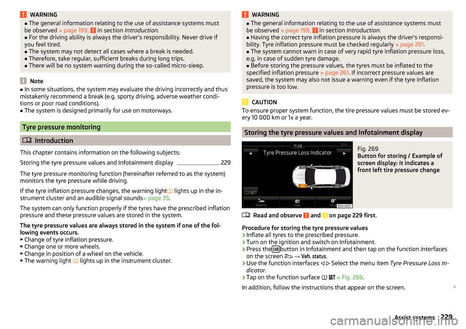
Fig. 269
Button for storing / Example of
screen display: it indicates a
front left tire pressure change
Read and observe and on page 229 first.
Procedure for storing the tyre pressure values
›
Inflate all tyres to the prescribed pressure.
›
Turn on the ignition and switch on Infotainment.
›
Press the button in Infotainment and then tap on the function interfaces
on the screen
→
Veh. status
.
›
Use the function interfaces
Select the menu item
Tyre Pressure Loss In-
dicator .
›
Tap on the function surface
» Fig. 269 .
In addition, follow the instructions that appear on the screen.
229Assist systems
Page 232 of 324
A message on the screen informs about the storage of the tyre pressure val-
ues.
Note
When a warning light in the instrument cluster appears, the affected tyre
can be displayed on the infotainment » Fig. 269.Towing device and trailer
Hitch
Introduction
This chapter contains information on the following subjects:
Description
231
Adjusting the ready position
231
Check the setting of the standby position
232
Assembling the bar ball – Step 1
232
Assembling the bar ball – Step 2
233
Check proper fitting
233
Removing the bar ball – Step 1
233
Removing the bar ball – Step 2
234
Vertical load with mounted accessories
235
The maximum trailer nose weight when towing a trailer is 75 kg, Vehicles with
four-wheel drive 80 kg and G-TEC vehicles 56 kg. Other data (e.g. shown on
the nameplate of the hitch) on provides information about the test values of
the device .
WARNING■ Before each time you make a journey when using the ball rod, check that
it is seated correctly and is secured in the mounting recess.■
When the knee-joint bar is not used and properly secured in the receiving
shaft, it is damaged or incomplete, this must not be used - there is a risk of
an accident.
■
Do not perform any modifications or changes to the towing device.
■
Keep the mounting recess of the towing device clean at all times. Such
dirt prevents the ball rod from being attached securely!
Note
If the towing device is removed completely, it must be replaced with the origi-
nal reinforcement of the rear bumper which is part of the mount for the towing
eye.230Driving
Page 234 of 324
2. Step - applies to both key versions›Grip the tow bar below the protective cap.›
Push release pin
C
in the direction of arrow
3
to the stop, and simultane-
ously push operating lever
D
in the direction of arrow
4
to the stop
» Fig. 272 .
Operating lever
D
remains locked in this position.
Check the setting of the standby position
Fig. 273
Ready position: Key Version 1 / key Version 2 / position of the
lever and the release bolt with two key versions
Read and observe
on page 230 first.
Correctly adjusted standby position » Fig. 273
Applies to key version 1 - the red marking on key
A
is pointing upwards.
Applies to key version 2 - the eye of the key
B
is pointing upwards.
Operating lever
C
is locked in the lower position.
The trigger pin
D
can be moved.
In the ready position, the key cannot be removed or turned into a different po-
sition. The ball bar is thus set ready for installation.
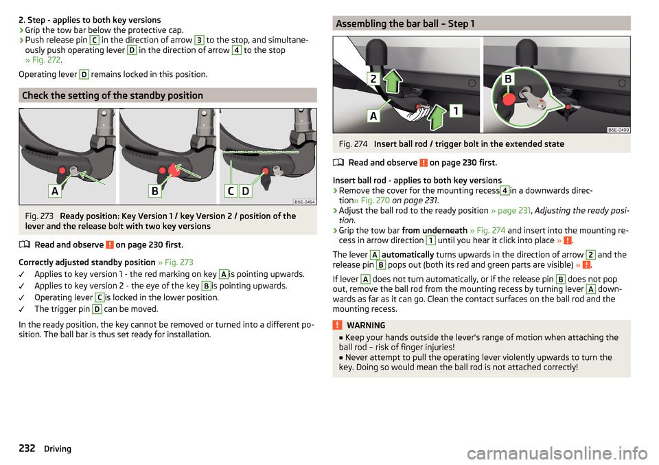
Assembling the bar ball – Step 1Fig. 274
Insert ball rod / trigger bolt in the extended state
Read and observe
on page 230 first.
Insert ball rod - applies to both key versions
›
Remove the cover for the mounting recess
4
in a downwards direc-
tion » Fig. 270 on page 231 .
›
Adjust the ball rod to the ready position » page 231, Adjusting the ready posi-
tion .
›
Grip the tow bar from underneath » Fig. 274 and insert into the mounting re-
cess in arrow direction
1
until you hear it click into place » .
The lever
A
automatically turns upwards in the direction of arrow
2
and the
release pin
B
pops out (both its red and green parts are visible) » .
If lever
A
does not turn automatically, or if the release pin
B
does not pop
out, remove the ball rod from the mounting recess by turning lever
A
down-
wards as far as it can go. Clean the contact surfaces on the ball rod and the
mounting recess.
WARNING■ Keep your hands outside the lever's range of motion when attaching the
ball rod – risk of finger injuries!■
Never attempt to pull the operating lever violently upwards to turn the
key. Doing so would mean the ball rod is not attached correctly!
232Driving
Page 235 of 324
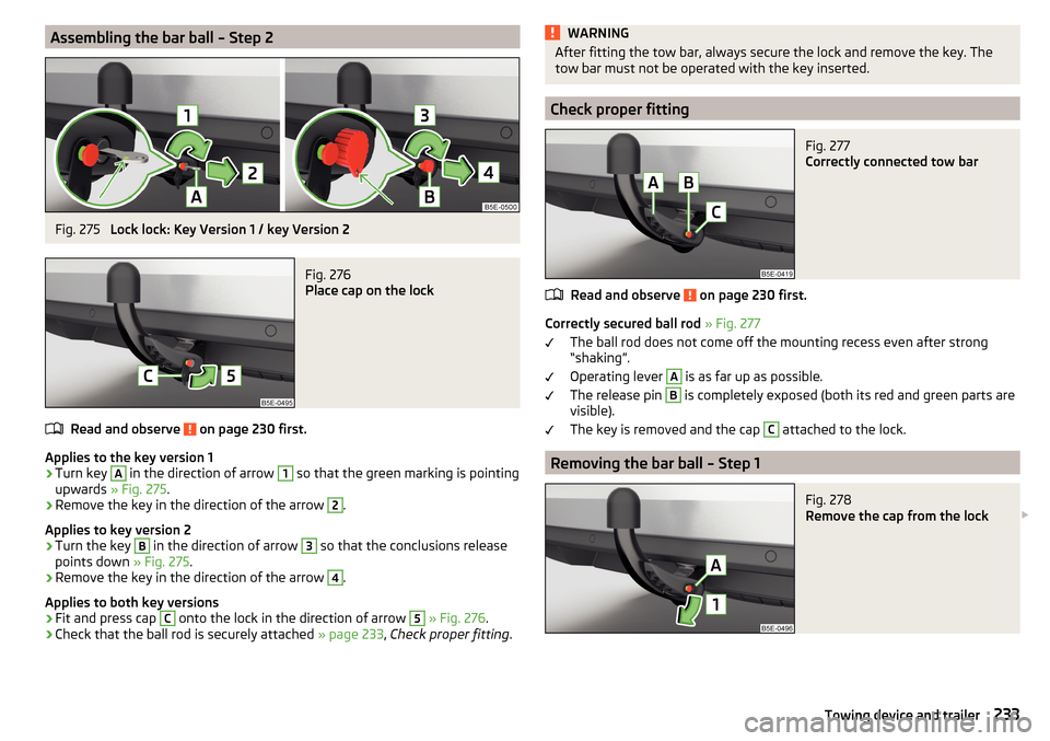
Assembling the bar ball – Step 2Fig. 275
Lock lock: Key Version 1 / key Version 2
Fig. 276
Place cap on the lock
Read and observe on page 230 first.
Applies to the key version 1
›
Turn key
A
in the direction of arrow
1
so that the green marking is pointing
upwards » Fig. 275 .
›
Remove the key in the direction of the arrow
2
.
Applies to key version 2
›
Turn the key
B
in the direction of arrow
3
so that the conclusions release
points down » Fig. 275.
›
Remove the key in the direction of the arrow
4
.
Applies to both key versions
›
Fit and press cap
C
onto the lock in the direction of arrow
5
» Fig. 276 .
›
Check that the ball rod is securely attached » page 233, Check proper fitting .
WARNINGAfter fitting the tow bar, always secure the lock and remove the key. The
tow bar must not be operated with the key inserted.
Check proper fitting
Fig. 277
Correctly connected tow bar
Read and observe on page 230 first.
Correctly secured ball rod » Fig. 277
The ball rod does not come off the mounting recess even after strong
“shaking”.
Operating lever
A
is as far up as possible.
The release pin
B
is completely exposed (both its red and green parts are
visible).
The key is removed and the cap
C
attached to the lock.
Removing the bar ball – Step 1
Fig. 278
Remove the cap from the lock
233Towing device and trailer
Page 236 of 324
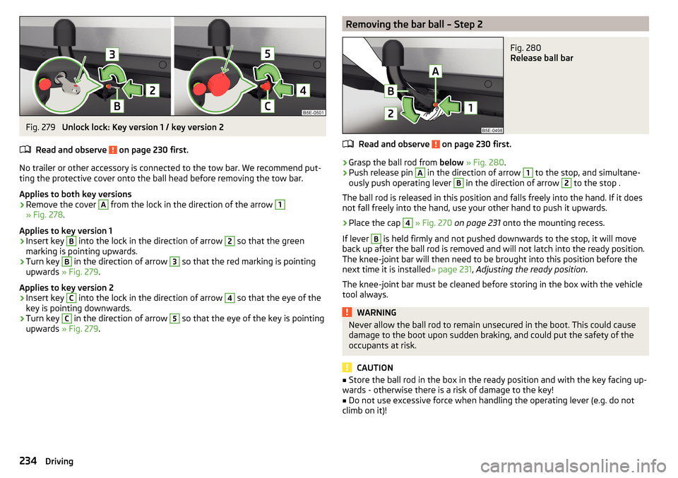
Fig. 279
Unlock lock: Key version 1 / key version 2
Read and observe
on page 230 first.
No trailer or other accessory is connected to the tow bar. We recommend put- ting the protective cover onto the ball head before removing the tow bar.
Applies to both key versions
›
Remove the cover
A
from the lock in the direction of the arrow
1
» Fig. 278 .
Applies to key version 1
›
Insert key
B
into the lock in the direction of arrow
2
so that the green
marking is pointing upwards.
›
Turn key
B
in the direction of arrow
3
so that the red marking is pointing
upwards » Fig. 279 .
Applies to key version 2
›
Insert key
C
into the lock in the direction of arrow
4
so that the eye of the
key is pointing downwards.
›
Turn key
C
in the direction of arrow
5
so that the eye of the key is pointing
upwards » Fig. 279 .
Removing the bar ball – Step 2Fig. 280
Release ball bar
Read and observe on page 230 first.
›
Grasp the ball rod from below » Fig. 280 .
›
Push release pin
A
in the direction of arrow
1
to the stop, and simultane-
ously push operating lever
B
in the direction of arrow
2
to the stop .
The ball rod is released in this position and falls freely into the hand. If it does not fall freely into the hand, use your other hand to push it upwards.
›
Place the cap
4
» Fig. 270 on page 231 onto the mounting recess.
If lever
B
is held firmly and not pushed downwards to the stop, it will move
back up after the ball rod is removed and will not latch into the ready position.
The knee-joint bar will then need to be brought into this position before the
next time it is installed » page 231, Adjusting the ready position .
The knee-joint bar must be cleaned before storing in the box with the vehicle tool always.
WARNINGNever allow the ball rod to remain unsecured in the boot. This could cause
damage to the boot upon sudden braking, and could put the safety of the
occupants at risk.
CAUTION
■ Store the ball rod in the box in the ready position and with the key facing up-
wards - otherwise there is a risk of damage to the key!■
Do not use excessive force when handling the operating lever (e.g. do not
climb on it)!
234Driving
Page 238 of 324
With the engine switched off, the vehicle battery is discharged by the connec-
ted consumers.
At low charge state of the vehicle battery, the power supply to the trailer (ac-
cessories) is interrupted.WARNING■ An improperly connected electrical installation of the trailer (accessories)
may result in an accident or serious injury from electrical shock.■
Do not make any adjustments to the electrical installation of the vehicle
and the trailer (accessories) - risk of an accident or serious injury from elec-
trical shock.
■
After the electrical connection between the vehicle and trailer (accessory)
the trailer / accessory lights should be checked for function.
■
Never use the securing eye to tow - The is a risk of an accident!
CAUTION
■ An improperly connected electrical installation of the trailer (accessories) can
lead to the inoperability of the vehicle electronics.■
The total power consumption of all the connected loads to the trailer power
supply must not exceed 350 watts, otherwise there is a risk of damage to the
electrical system of the vehicle.
Loading a trailer
Correct the tyre inflation pressure on the vehicle for “full load” » page 261.
Distribution of the cargo
Distribute the cargo in the trailer in such a way that heavy items are located as
close to the trailer axle as possible. Secure the load from slipping.
The distribution of the weight is very poor if your vehicle is unladen and the
trailer is laden. Nevertheless, maintain a particularly low speed if you cannot
avoid driving with this combination.WARNINGSliding cargo can significantly adversely affect stability and driving safety -
risk of accident!
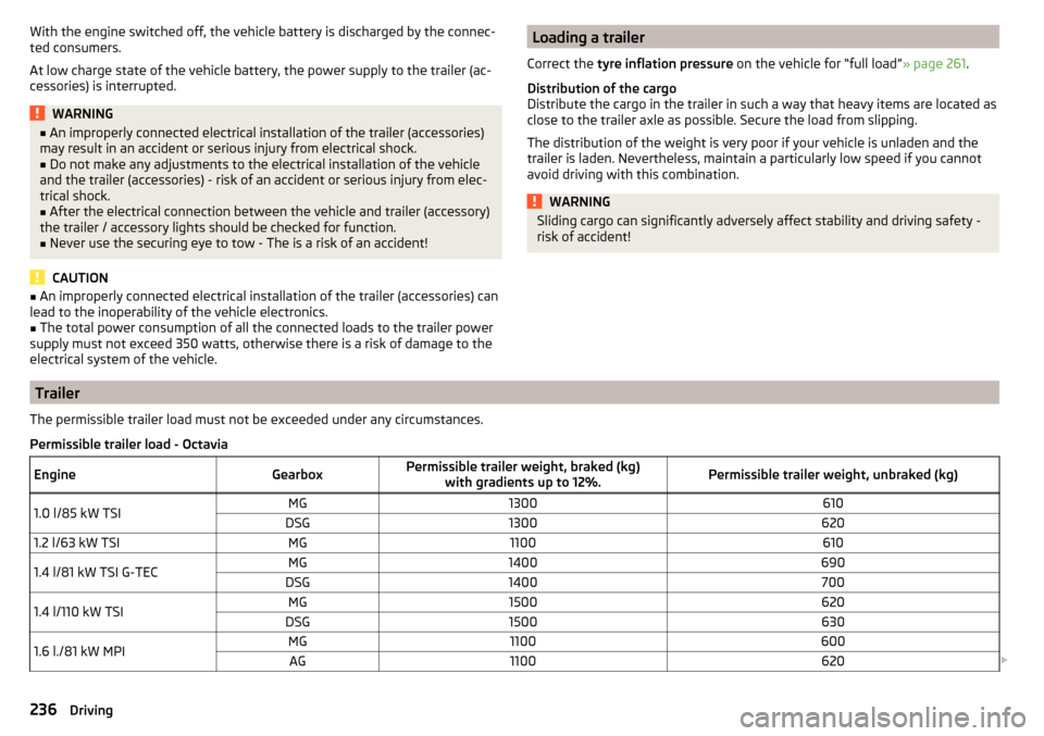
Trailer
The permissible trailer load must not be exceeded under any circumstances.Permissible trailer load - OctaviaEngineGearboxPermissible trailer weight, braked (kg) with gradients up to 12%.Permissible trailer weight, unbraked (kg)1.0 l/85 kW TSIMG1300610DSG13006201.2 l/63 kW TSIMG11006101.4 l/81 kW TSI G-TECMG1400690DSG14007001.4 l/110 kW TSIMG1500620DSG15006301.6 l./81 kW MPIMG1100600AG1100620 236Driving
Page 241 of 324
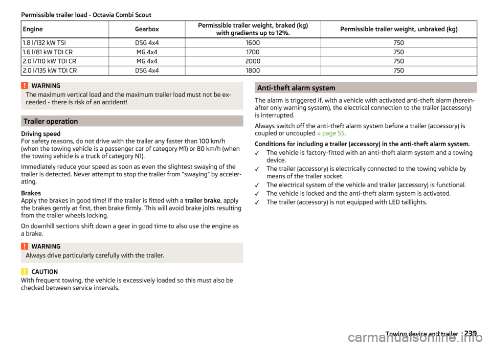
Permissible trailer load - Octavia Combi ScoutEngineGearboxPermissible trailer weight, braked (kg)with gradients up to 12%.Permissible trailer weight, unbraked (kg)1.8 l/132 kW TSIDSG 4x416007501.6 l/81 kW TDI CRMG 4x417007502.0 l/110 kW TDI CRMG 4x420007502.0 l/135 kW TDI CRDSG 4x41800750WARNINGThe maximum vertical load and the maximum trailer load must not be ex-
ceeded - there is risk of an accident!
Trailer operation
Driving speed
For safety reasons, do not drive with the trailer any faster than 100 km/h
(when the towing vehicle is a passenger car of category M1) or 80 km/h (when
the towing vehicle is a truck of category N1).
Immediately reduce your speed as soon as even the slightest swaying of the
trailer is detected. Never attempt to stop the trailer from “swaying” by acceler-
ating.
Brakes
Apply the brakes in good time! If the trailer is fitted with a trailer brake, apply
the brakes gently at first, then brake firmly. This will avoid brake jolts resulting
from the trailer wheels locking.
On downhill sections shift down a gear in good time to also use the engine as
a brake.
WARNINGAlways drive particularly carefully with the trailer.
CAUTION
With frequent towing, the vehicle is excessively loaded so this must also be
checked between service intervals.Anti-theft alarm system
The alarm is triggered if, with a vehicle with activated anti-theft alarm (herein-
after only warning system), the electrical connection to the trailer (accessory)
is interrupted.
Always switch off the anti-theft alarm system before a trailer (accessory) is
coupled or uncoupled » page 55.
Conditions for including a trailer (accessory) in the anti-theft alarm system. The vehicle is factory-fitted with an anti-theft alarm system and a towing
device.
The trailer (accessory) is electrically connected to the towing vehicle by
means of the trailer socket.
The electrical system of the vehicle and trailer (accessory) is functional.
The vehicle is locked and the anti-theft alarm system is activated.
The trailer (accessory) is not equipped with LED taillights.239Towing device and trailer
Page 242 of 324

General Maintenance
Care and maintenance
Service work, adjustments and technical alterations
Introduction
This chapter contains information on the following subjects:
Vehicle operation in different weather conditions
240
Statutory checks
240
ŠKODA service partner
240
ŠKODA Original parts
241
ŠKODA Original accessories
241
Spoiler
241
Component protection
241
Airbags
241
Acceptance and recycling of used vehicles
242
The instructions and guidelines from ŠKODA AUTO a.s. must be observed when
using accessories or carrying out any modifications, repairs or technical altera-
tions to your vehicle.
Adhering to these instructions and guidelines helps ensure road safety and
helps keep your vehicle in a good technical condition.
WARNING■ Adjustments, repairs and technical changes to the vehicle should only be
carried out by a specialist. Work carried out incorrectly (including work on
the electronic components and their software) can result in malfunctions -
there is a risk of accident and, potentially, increased wear on parts!■
We recommend that you use only ŠKODA Original Accessories and ŠKODA
Original Parts which have been expressly approved for use on your vehicle.
Reliability, safety and suitability for your vehicle are guaranteed with these.
■
Do not use any products which have not been approved by ŠKODA AUTO,
even though these may be products with a type approval or which have
been approved by a nationally recognised testing laboratory.
Vehicle operation in different weather conditions
Read and observe
on page 240 first.
If you would like to operate your vehicle in countries other than those with its
intended weather conditions, please contact a ŠKODA Partner. He or she will
advise you if certain precautions need to be taken to ensure the full function-
ing of the vehicle or to prevent damage (e.g. coolant, changing the battery or
similar).
Statutory checks
Read and observe
on page 240 first.
Many countries have legislation requiring the operational reliability, safety and,
where applicable, roadworthiness and/or exhaust gas properties of a vehicle
to be tested at regular intervals. These tests can be carried out by workshops
or testing stations that have been legally authorized for this purpose.
The ŠKODA Service partners can prepare your vehicle for the official inspec-
tions, so as to ensure that it passes.
Even if you want to take your vehicle to an officially approved test centre for
prior checking in preparation for a legally required test, we recommend that
you consult your ŠKODA Service Partner beforehand.
ŠKODA service partner
Read and observe
on page 240 first.
All ŠKODA service partners work according to the instructions and guidelines
from ŠKODA AUTO a.s. All service and repair work is therefore carried out on
time and at the appropriate quality. Adhering to these instructions and guide-
lines helps ensure road safety and helps keep your vehicle in a good technical
condition.
We therefore advise you to have all modifications, repairs and technical altera-
tions to your vehicle carried out by a ŠKODA Service Partner.
240General Maintenance
Page 243 of 324
ŠKODA Original partsRead and observe
on page 240 first.
We recommend the use of ŠKODA Genuine Parts for your vehicle, as these
parts are approved by ŠKODA AUTO. These parts comply wholly with ŠKODA
AUTO regulations and are identical to the parts used in series production.
ŠKODA AUTO is able to warrant the safety, suitability, and long life of these
products.
ŠKODA Service Partners are liable for any defects of ŠKODA Genuine Parts for
a period of 2 years after sale in accordance with the materials defect liability,
unless agreed otherwise in the purchase agreement.
ŠKODA Original accessories
Read and observe
on page 240 first.
If you wish to fit accessories to your vehicle, you should remember the follow-
ing:
We recommend that you use ŠKODA Genuine Accessories in your vehicle.
ŠKODA AUTO has selected these accessories to ensure that they are reliable,
safe and suitable for your particular vehicle. Although we constantly monitor
the market, we are not able to assess or vouch the suitability of other products
for your vehicle, despite the fact that some products may have operational ap-
proval or may have been approved by a nationally recognised testing laborato-
ry.
ŠKODA Service Partners are liable for any defects of ŠKODA Genuine Accesso-
ries for a period of 2 years after installation or delivery in accordance with the
materials defect liability, unless agreed otherwise in the purchase agreement
or any other agreements.
Spoiler
Read and observe
on page 240 first.
WARNINGIf your vehicle is equipped with a Genuine Accessories spoiler on the front
bumper in combination with the spoiler on the boot lid, the following in-
structions must be observed - otherwise there is a risk of accidents and se-
rious injuries!■
The vehicle can only be equipped with a spoiler on the front bumper in
combination with the corresponding spoiler on the boot lid.
■
A Genuine Accessories spoiler cannot be fitted to the front bumper either
on its own (without a spoiler on the boot lid) or in combination with an un-
suitable spoiler on the boot lid.
■
We recommend that you consult the ŠKODA Service Partner for any re-
pairs to or replacement, addition or removal of spoilers.
■
Unprofessional work carried out on the spoilers of your vehicle may result
in malfunction.
Component protection
Read and observe
on page 240 first.
Some electronic vehicle components (such as the instrument cluster) are fac-
tory-equipped with component protection. This ensures the functional limita-
tion of these components in a non-legitimate installation in another vehicle
(e.g. after a theft) or operation outside the vehicle.
Airbags
Read and observe
on page 240 first.
WARNING■Modifications, repairs and technical alterations that have been carried out
unprofessionally can cause damage and operational faults, and can also se-
riously impair the effectiveness of the airbag system – risk of accident and
fatal injury!■
A change to the vehicle's wheel suspension, including the use of non-ap-
proved wheels and tire combinations, can impair the functioning of the air-
bag system - There is a risk of accidents and fatal injury!
241Care and maintenance