display SKODA OCTAVIA 2016 3.G / (5E) Owner's Manual
[x] Cancel search | Manufacturer: SKODA, Model Year: 2016, Model line: OCTAVIA, Model: SKODA OCTAVIA 2016 3.G / (5E)Pages: 324, PDF Size: 48.85 MB
Page 229 of 324
WARNING■The general information relating to the use of assistance systems must
be observed » page 199, in section Introduction .■
Vertical traffic signs must always take precedence over the traffic signs
shown in the display. The driver is always responsible for correctly assess-
ing the traffic situation.
■
On the system side, only a traffic sign display is undertaken, neither a
warning when limit is exceeded or driving speed adjustment is undertaken!
■
Speed specifications in the displayed road signs refer to the customary
speed units. For example, the view
in the display can therefore refer to
km / h or mph, specific to the country.
WARNINGThe traffic signs may not be displayed or displayed incorrectly in the system
e.g. in the following situations.■
When visibility is poor, (e.g. fog, heavy rain, thick snowfall).
■
The sensor is blinded by the sun or oncoming traffic.
■
The field of view of the sensor is limited by an obstacle or a preceding ve-
hicle.
■
Travelling at high speed.
■
The traffic signs are covered (e.g. by trees, snow or dirt).
■
The traffic signs are not standard (round with a red border) or are dam-
aged.
■
The traffic signs are attached to flashing neon signs.
■
The traffic signs were changed (the navigation data are out of date).
Note
The system is only available in some countries.
Settings in Infotainment
Read and observe
on page 227 first.
›
Press the button, then tap on the function surface
→
Driver assistance
.
■ Dynamic Road Sign Display - Settings for the Dynamic Road Sign Display
■
Show in instrument cluster
- Activation/deactivation of the additional traffic
signs in the display of the instrument cluster
■
Speed warning::
» page 221 - Setting a warning when exceeding the speed
limit
■ Trailer recognition
■Show road signs relevant to trailers
- Activating / deactivating the display of road
signs relevant to trailers
■
Use for route calculation
- Activation / deactivation taking trailers in account for
route calculation in navigation
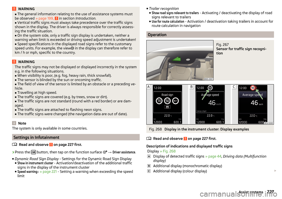
Operation
Fig. 267
Sensor for traffic sign recogni-
tion
Fig. 268
Display in the instrument cluster: Display examples
Read and observe
on page 227 first.
Description of indications and displayed traffic signs
Display » Fig. 268Display of detected traffic signs » page 44, Driving data (Multifunction
display)Additional display (monochromatic display)Additional display (colour display) 227Assist systems
Page 230 of 324
The system can display the following (vertical) traffic signs where identified.▶ Speed limit.
▶ Overtaking prohibited.
Additional signs, such as 'when wet' or signs which only apply for a limited
time can also be displayed.
The system displays only traffic signs that are in the “viewing area” of the sen-
sor » Fig. 267 .
Data from the sensor is supplemented by information from the Infotainment
Navigation. This is the reason why traffic signs with maximum speeds can also
be shown on sections of roads which do not have any traffic signs.
Mode when towing a trailer
For vehicles with a factory-fitted towing device the display for the trailer oper-
ation applicable road signs can be enabled or disabled in the Infotainment dis-
play » page 227 , Settings in Infotainment .
Additional display
Read and observe
on page 227 first.
If the menu item Road sign is currently not shown » Fig. 268 on page 227 -
,
the road sign with the speed limit will appear in the upper display area of the
instrument cluster » Fig. 268 on page 227 -
,
.
If several traffic signs are detected simultaneously, in some cases the next
traffic sign will also be displayed in the colour display - » Fig. 268 on page 227 -
.
All detected traffic signs can be displayed via the multifunction display in the
menu item Traffic Sign Recognition » Fig. 268 on page 227 -
.
The additional display can be activated / deactivated in Infotain-
ment » page 227 .
Malfunctions and information messages
Read and observe
on page 227 first.
If, for some unknown reason, the system is not available, an appropriate mes-
sage appears in the display of the instrument cluster.
Sensor covered / dirty
If the screen in the sensor area is dirty, iced or misted, a caution to clean the
screen appears. Clean the windscreen or remove the obstacles from the sen-
sor area.
System fault
In the case of a system fault, an error message appears. Seek help from a spe-
cialist garage.
System limitation (Navigation data not available)
If the Infotainment Navigation submits no data, a message regarding the limi- tation of the system function appears. Check whether the map documents are
up to date or whether the vehicle is currently in a location for which no naviga-
tion data are available.
Traffic signs unavailable
No speed restriction is detected, a message is displayed regarding the unavail-
ability of road signs.
Fatigue detection
The fatigue detection system (hereinafter referred to as system) recommends
the driver takes a break from driving when driver fatigue can be detected due
to the driver's steering behaviour.
From the starting of the journey, the system evaluates the steering behaviour
at speeds 65-200 km/h. If, while driving, there have been changes in the steer-
ing behaviours that are evaluated by the system as indicating possible fatigue,
a break recommendation is issued.
Conditions under which a break from driving is detected by the system ▶ The vehicle is stopped and the ignition is turned off.
▶ The vehicle is stopped, the seat belt is taken off and the driver's door is
opened.
▶ The vehicle is stopped for more than 15 minutes.
If none of these conditions are met or if the driving style is not changed, the
system recommends a driving break again after 15 minutes.
The system can be activated/deactivated in the Infotainment menu
→
→
Driver assistance
.
Pause recommendation
The icon appears and the following message for a few seconds in the display
of the instrument cluster and a message about the detected fatigue. An au-
dible signal is also emitted.
228Driving
Page 231 of 324
WARNING■The general information relating to the use of assistance systems must
be observed » page 199, in section Introduction .■
For the driving ability is always the driver's responsibility. Never drive if
you feel tired.
■
The system may not detect all cases where a break is needed.
■
Therefore, take regular, sufficient breaks during long trips.
■
There will be no system warning during the so-called micro-sleep.
Note
■ In some situations, the system may evaluate the driving incorrectly and thus
mistakenly recommend a break (e.g. sporty driving, adverse weather condi-
tions or poor road conditions).■
The system is designed primarily for use on motorways.
Tyre pressure monitoring
Introduction
This chapter contains information on the following subjects:
Storing the tyre pressure values and Infotainment display
229
The tyre pressure monitoring function (hereinafter referred to as the system)
monitors the tyre pressure while driving.
If the tyre inflation pressure changes, the warning light
lights up in the in-
strument cluster and an audible signal sounds » page 35.
The system can only function properly if the tyres have the prescribed inflation
pressure and these pressure values are stored in the system.
The tyre pressure values are always stored in the system if one of the fol-
lowing events occurs.
▶ Change of tyre inflation pressure.
▶ Change one or more wheels.
▶ Change in position of a wheel on the vehicle.
▶ The warning light
lights up in the instrument cluster.
WARNING■
The general information relating to the use of assistance systems must
be observed » page 199, in section Introduction .■
Having the correct tyre inflation pressure is always the driver's responsi-
bility. Tyre inflation pressure must be checked regularly » page 261.
■
The system cannot warn in case of very rapid tyre inflation pressure loss,
e.g. in case of sudden tyre damage.
■
Before storing the pressure values, the tyres must be inflated to the
specified inflation pressure » page 261. If incorrect pressure values are
saved, the system may also not issue a warning even if the tyre inflation
pressure is too low.
CAUTION
To ensure proper system function, the tire pressure values must be stored ev-
ery 10 000 km or 1x a year.
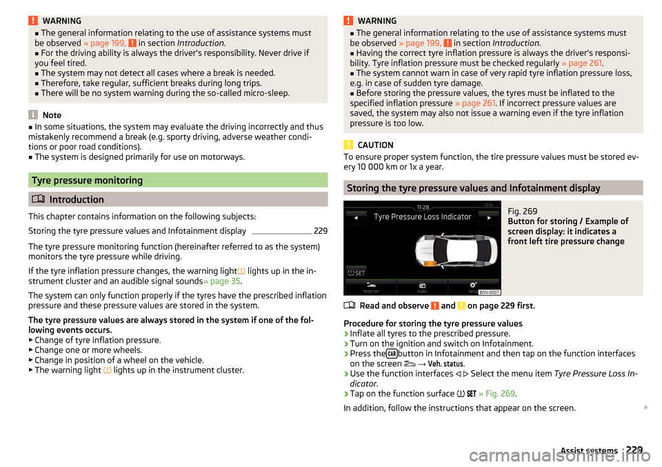
Storing the tyre pressure values and Infotainment display
Fig. 269
Button for storing / Example of
screen display: it indicates a
front left tire pressure change
Read and observe and on page 229 first.
Procedure for storing the tyre pressure values
›
Inflate all tyres to the prescribed pressure.
›
Turn on the ignition and switch on Infotainment.
›
Press the button in Infotainment and then tap on the function interfaces
on the screen
→
Veh. status
.
›
Use the function interfaces
Select the menu item
Tyre Pressure Loss In-
dicator .
›
Tap on the function surface
» Fig. 269 .
In addition, follow the instructions that appear on the screen.
229Assist systems
Page 232 of 324
A message on the screen informs about the storage of the tyre pressure val-
ues.
Note
When a warning light in the instrument cluster appears, the affected tyre
can be displayed on the infotainment » Fig. 269.Towing device and trailer
Hitch
Introduction
This chapter contains information on the following subjects:
Description
231
Adjusting the ready position
231
Check the setting of the standby position
232
Assembling the bar ball – Step 1
232
Assembling the bar ball – Step 2
233
Check proper fitting
233
Removing the bar ball – Step 1
233
Removing the bar ball – Step 2
234
Vertical load with mounted accessories
235
The maximum trailer nose weight when towing a trailer is 75 kg, Vehicles with
four-wheel drive 80 kg and G-TEC vehicles 56 kg. Other data (e.g. shown on
the nameplate of the hitch) on provides information about the test values of
the device .
WARNING■ Before each time you make a journey when using the ball rod, check that
it is seated correctly and is secured in the mounting recess.■
When the knee-joint bar is not used and properly secured in the receiving
shaft, it is damaged or incomplete, this must not be used - there is a risk of
an accident.
■
Do not perform any modifications or changes to the towing device.
■
Keep the mounting recess of the towing device clean at all times. Such
dirt prevents the ball rod from being attached securely!
Note
If the towing device is removed completely, it must be replaced with the origi-
nal reinforcement of the rear bumper which is part of the mount for the towing
eye.230Driving
Page 244 of 324
WARNING■No changes may be made to airbag system components, the front bump-
er and the bodywork.■
Any work on the airbag system including the installation and removal of
system components due to other repair work (e.g. removal of the steering
wheel) must only be carried out by a specialist garage.
■
Do not manipulate individual parts of the airbag system, as this might re-
sult in the airbag being deployed.
■
If the airbag has been deployed, the airbag system must be replaced.
WARNINGThe airbag system operates using pressure sensors located in the front
doors. For this reason, no adjustments may be carried out to the doors or
door panels (e.g. installation of additional loudspeakers). Resulting damage
can impair the functioning of the airbag system -There is a risk of accidents
and fatal injuries! The following guidelines must therefore be observed.■
Any work on the front doors and their door panels must be carried out by
a specialist garage.
■
Never drive the vehicle with the inner door panels removed or with open-
ings in the panelling.
Acceptance and recycling of used vehicles
Read and observe
on page 240 first.
All new ŠKODA vehicles are 95% recyclable.
Service intervals
Introduction
This chapter contains information on the following subjects:
Overview of service intervals
243
Fixed service intervals QI1 - QI4
243
Variable service interval QI6
243
Digital Service Plan
244
The service interval display in the display of the instrument cluster will remind
you to carry out every service stipulated by the manufacturer at the right time
in order to prevent you from forgetting any » page 48.
The completion of services can be verified through the printed verification
from the digital service schedule and the respective receipts.
The specified service intervals are tailored to normal operating conditions.
In the case of aggravated operating conditions, it will be necessary to have
some service work carried out before the date of the next regular service or
between the specified service intervals. This applies mainly to the cleaning or
the replacement of the air filter insert in regions with heavy dust pollution as
well as checking and replacing the toothed belt, but also to vehicles with die-
sel particle filters, which can put greater strain on the engine oil.
The following is taken to mean aggravated operating conditions:
▶ Fuel containing sulphur.
▶ Frequent short trips.
▶ Longer periods of engine idling (e.g. taxis).
▶ Operation in areas with heavy dust pollution.
▶ Frequent trailer operation.
▶ Predominantly stop-and-go traffic as is e.g. often the case in city driving.
▶ Operation predominantly during winter.
You will be told at the specialist garage whether the operating conditions of
your vehicle may make it necessary for service work to be carried out between
the normal service intervals.
Different service charges may apply according to the particular scope of work
required, the vehicle type and specification, and your vehicle’s condition.
Note
■ The customer is responsible for covering the cost of all services including
changing or replenishing the oil, even during the warranty period, unless sta-
ted otherwise in the ŠKODA AUTO warranty terms or other agreements.■
You will be informed about the service checks and actions at each service by
the specialist garage.
242General Maintenance
Page 245 of 324
Overview of service intervalsFig. 283
Vehicle data: Service Interval
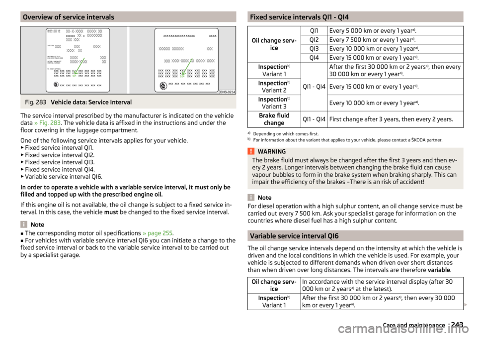
The service interval prescribed by the manufacturer is indicated on the vehicle
data » Fig. 283 . The vehicle data is affixed in the instructions and under the
floor covering in the luggage compartment.
One of the following service intervals applies for your vehicle. ▶ Fixed service interval QI1.
▶ Fixed service interval QI2.
▶ Fixed service interval QI3.
▶ Fixed service interval QI4.
▶ Variable service interval QI6.
In order to operate a vehicle with a variable service interval, it must only be
filled and topped up with the prescribed engine oil.
If this engine oil is not available, the oil change is subject to a fixed service in-
terval. In this case, the vehicle must be changed to the fixed service interval.
Note
■
The corresponding motor oil specifications » page 255.■For vehicles with variable service interval QI6 you can initiate a change to the
fixed service interval or back to the variable service interval to be carried out
by a specialist garage.Fixed service intervals QI1 - QI4
Oil change serv- ice
QI1Every 5 000 km or every 1 year a)
.QI2Every 7 500 km or every 1 year a)
.QI3Every 10 000 km or every 1 year a)
.QI4Every 15 000 km or every 1 year a)
.Inspection b)
Variant 1
QI1 - QI4
After the first 30 000 km or 2 years a)
, then every
30 000 km or every 1 year a)
.Inspection b)
Variant 2Every 15 000 km or every 1 year a)
.Inspection b)
Variant 3Every 10 000 km or every 1 year a)
.Brake fluid
changeQI1 - QI4First change after 3 years, then every 2 years.a)
Depending on which comes first.
b)
For information about the variant that applies to your vehicle, please contact a ŠKODA partner.
WARNINGThe brake fluid must always be changed after the first 3 years and then ev-
ery 2 years. Longer intervals between changing the brake fluid can cause
vapour bubbles to form in the brake system when braking sharply. This can
impair the efficiency of the brakes –There is an risk of accident!
Note
For diesel operation with a high sulphur content, an oil change service must be
carried out every 7 500 km. Ask your specialist garage for information on the
countries where diesel fuel has a high sulphur content.
Variable service interval QI6
The oil change service intervals depend on the intensity at which the vehicle is
driven and the local conditions in which the vehicle is used. For example, your
vehicle is subjected to different demands when driven over short distances
than when driven over long distances. The intervals are therefore variable.
Oil change serv-
iceIn accordance with the service interval display (after 30
000 km or 2 years a)
at the latest).Inspection b)
Variant 1After the first 30 000 km or 2 years a)
, then every 30 000
km or every 1 year a)
. 243Care and maintenance
Page 256 of 324
›Raise the bonnet in the direction of the arrow 3.›Remove the lid prop in the direction of arrow 4 from the holder.›
Secure the open flap inserting the end of the post into the opening in the di-
rection of arrow
5
.
Close the flap
›
Lift the bonnet.
›
Decouple the bonnet support and press into the holder designed to hold it.
›
Drop down the bonnet lid from a height of about 20 cm applying light pres-
sure until it clicks safely into place.
If the bonnet lid is not properly closed, the display of the instrument cluster will show a representation of a vehicle with an open bonnet lid.
WARNING■ Never drive with the bonnet lid not properly closed - risk of accident!■Make sure that when closing the bonnet, no body parts are crushed -
there is danger of injury!
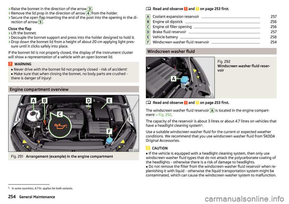
Engine compartment overview
Fig. 291
Arrangement (example) in the engine compartment
Read and observe and on page 253 first.
Coolant expansion reservoir
257
Engine oil dipstick
256
Engine oil filler opening
256
Brake fluid reservoir
257
Vehicle battery
258
Windscreen washer fluid reservoir
254
Windscreen washer fluid
Fig. 292
Windscreen washer fluid reser-
voir
Read and observe and on page 253 first.
The windscreen washer fluid reservoir
A
is located in the engine compart-
ment » Fig. 292 .
The capacity of the reservoir is about 3 litres or about 4.7 litres on vehicles that
have a headlight cleaning system 1)
.
Use a suitable windscreen washer fluid for the current or expected weather
conditions. We recommend that you use windscreen washer fluid from ŠKODA
Original Accessories.
CAUTION
■ If the vehicle is equipped with a headlight cleaning system, then only use
windscreen washer fluid types that do not attack the polycarbonate coating of
the headlights - otherwise there is a risk of damage to headlights.■
Do not remove the filter from the windscreen washer fluid reservoir when re-
plenishing it with liquid - otherwise the liquid transportation system might be
contaminated, which can cause the windscreen washer system to malfunction.
ABCDEF1)
In some countries, 4.7 ltr. applies for both variants.
254General Maintenance
Page 260 of 324
Specification - The brake fluid must comply with the standard VW 501 14 (this
standard meets the requirements of FMVSS 116 DOT4).WARNING■ The following instructions must be followed at all times when working on
the engine compartment » page 252.■
If the fluid level drops significantly within a short time or if it drops below
the “MIN” » Fig. 295mark, this may be an indication of a leak in the brake
system.
Stop driving - There is a risk of an accident! Seek help from a
specialist garage.
Note
■ The brake fluid is changed as part of a compulsory inspection service.■A low brake fluid level which is too low is indicated by the warning light
being shown on the display of the instrument cluster as well as the corre-
sponding message » page 33. We still recommend inspecting the brake fluid
level in the reservoir from time to time.
Vehicle battery
Introduction
This chapter contains information on the following subjects:
Check condition
259
Charging
259
Disconnect/reconnect and change
260
The vehicle battery represents a power source for the motor to start and for the supply of electrical consumers in the car.
Automatic consumer shutdown - Discharge protection of the vehicle battery
The on-board power supply system tries to prevent the vehicle battery from
discharging in the following ways when it is subject to heavy loading. ▶ By increasing the engine idle speed.
▶ Through the power limitation of certain loads.
▶ By switching off some loads(heated seats, heated rear window) for as long
as necessary.
Warning symbols on the vehicle batterySymbolMeaningAlways wear eye protection!Battery acid is severely caustic. Always wear gloves and eye pro-
tection!Keep fire, sparks, open flames and lit cigarettes well clear of the
vehicle battery!When charging the vehicle battery, a highly explosive gas mixture
is produced!Keep children away from the vehicle battery!WARNINGBattery acid is highly corrosive - it can cause injury, chemical burns or poi-
soning! Corrosive vapours in the air irritate and damage the respiratory
tract and the eyes. The following guidelines must be observed.■
Always wear protective gloves, eye and skin protection when handling
the vehicle battery.
■
If your eyes or skin come into contact with the electrolytic fluid, immedi-
ately wash the affected area for a few minutes long with a lot of water. Get
medical assistance without delay.
■
Keep the vehicle battery away from people who are not completely inde-
pendent (e.g. children).
■
Do not tilt the battery otherwise battery electrolyte may flow out of the
battery vent openings.
WARNINGWorking on the car battery may cause explosion, fire, injury or chemical
burn! The following guidelines must be observed.■
Do not smoke, use open flames or light or transmitting devices.
■
A discharged vehicle battery may freeze slightly. Never charge up a fro-
zen or thawed vehicle battery. Replace a frozen vehicle battery.
■
Never use a damaged vehicle battery.
■
Do not connect the battery terminals, bridging the two poles will cause a
short circuit.
258General Maintenance
Page 261 of 324
CAUTIONEnsure that battery acid does not come into contact with the bodywork –
There is a risk of damage to the vehicle.
Note
■ We recommend having all work on the vehicle battery carried out by a spe-
cialist garage.■
You should replace batteries older than 5 years.
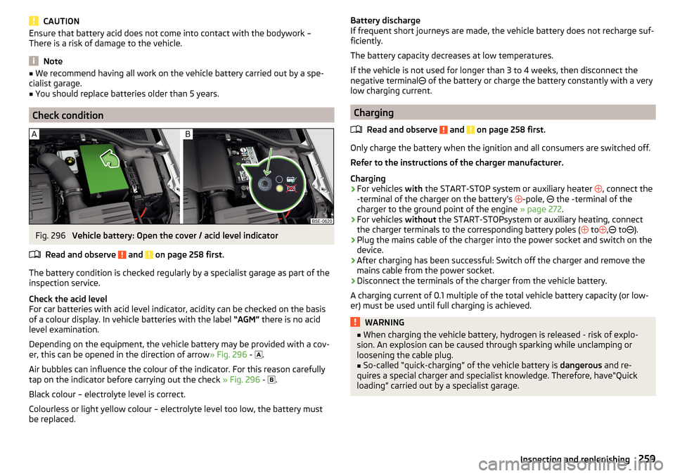
Check condition
Fig. 296
Vehicle battery: Open the cover / acid level indicator
Read and observe
and on page 258 first.
The battery condition is checked regularly by a specialist garage as part of the
inspection service.
Check the acid level
For car batteries with acid level indicator, acidity can be checked on the basis
of a colour display. In vehicle batteries with the label “AGM” there is no acid
level examination.
Depending on the equipment, the vehicle battery may be provided with a cov-
er, this can be opened in the direction of arrow » Fig. 296 -
.
Air bubbles can influence the colour of the indicator. For this reason carefully
tap on the indicator before carrying out the check » Fig. 296 -
.
Black colour – electrolyte level is correct.
Colourless or light yellow colour – electrolyte level too low, the battery must be replaced.
Battery discharge
If frequent short journeys are made, the vehicle battery does not recharge suf- ficiently.
The battery capacity decreases at low temperatures.
If the vehicle is not used for longer than 3 to 4 weeks, then disconnect the
negative terminal
of the battery or charge the battery constantly with a very
low charging current.
Charging
Read and observe
and on page 258 first.
Only charge the battery when the ignition and all consumers are switched off.
Refer to the instructions of the charger manufacturer.
Charging
›
For vehicles with the START-STOP system or auxiliary heater
, connect the
-terminal of the charger on the battery’s -pole,
the -terminal of the
charger to the ground point of the engine » page 272.
›
For vehicles without the START-STOPsystem or auxiliary heating, connect
the charger terminals to the corresponding battery poles ( to
,
to
).
›
Plug the mains cable of the charger into the power socket and switch on the
device.
›
After charging has been successful: Switch off the charger and remove the
mains cable from the power socket.
›
Disconnect the terminals of the charger from the vehicle battery.
A charging current of 0.1 multiple of the total vehicle battery capacity (or low-
er) must be used until full charging is achieved.
WARNING■ When charging the vehicle battery, hydrogen is released - risk of explo-
sion. An explosion can be caused through sparking while unclamping or
loosening the cable plug.■
So-called “quick-charging” of the vehicle battery is dangerous and re-
quires a special charger and specialist knowledge. Therefore, have“Quick
loading” carried out by a specialist garage.
259Inspecting and replenishing
Page 291 of 324
The approved tyres and rim sizes for your vehicle are listed in the vehicle's
technical documentation (the so called COC document) and this also states the
declaration of conformity.
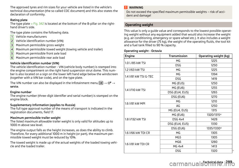
Rating plate
The type plate » Fig. 342 is located at the bottom of the B-pillar on the right-
hand driver's side.
The type plate contains the following data. Vehicle manufacturers
Vehicle identification number (VIN)
Maximum permissible gross weight
Maximum permissible towed weight (towing vehicle and trailer)
Maximum permissible front axle load
Maximum permissible rear axle load
Vehicle identification number (VIN)
The vehicle identification number - VIN (vehicle body number) is stamped into
the engine compartment on the right hand suspension strut dome. This num-
ber is also located on a sign on the lower left hand edge below the windscreen
(together with a VIN bar code), and on the type plate.
The VIN number can also be displayed in the Infotainment menu
→
→
service
.
Engine number
The engine number (three-digit identifier and serial number) is stamped on the
engine block.
Supplementary Information (applies to Russia)
The full type approval number of the means of transport is indicated in the
registration documents, field 17.
Maximum permissible trailer weight
The listed maximum allowable trailer weight is only valid for altitudes up to
1000 m above sea level.
The engine output falls as the height increases, as does the ability to climb.
Therefore, for every additional 1000 m in height (or part), the maximum per-
missible towed weight must be reduced by 10%.
The towed weight is made up of the actual weights of the loaded towing vehi-
cle and the loaded trailer.
123456WARNINGDo not exceed the specified maximum permissible weights – risk of acci-
dent and damage!
Operating weight
This value is only a guide value and corresponds to the lowest possible operat-
ing weight without any equipment added that would also increase the weight
(e.g. air conditioning, emergency or spare wheel etc.). It also includes a weight
allowance for the driver (75 kg), the weight of the operating fluids, the tool kit
and a fuel tank filled to 90 % capacity.
Operating weight - Octavia
EngineTransmissionOperating weight (kg)1.0 l./85 kW TSIMG1225DSG12501.2 l/63 kW TSIMG12251.4 l/81 kW TSI G-TECMG1394DSG1419
1.4 l/110 kW TSI
MG (EU5)1250MG (EU6)1255DSG (EU4, EU5)1265DSG (EU6)12701.6 l/81 kW MPIMG1210AG1250
1.8 l/132 kW TSI
MG (EU4, EU5)1315MG (EU6)1320/1315 a)DSG 4x41428DSG (EU4, EU5)1330DSG (EU6)1335/1330 a)1.6 l/66 kW TDI CRMG1305
1.6 l/81 kW TDI CR
MG51305MG61280MG 4x41413DSG1320
289Technical data