removing SKODA OCTAVIA 2016 3.G / (5E) Owner's Guide
[x] Cancel search | Manufacturer: SKODA, Model Year: 2016, Model line: OCTAVIA, Model: SKODA OCTAVIA 2016 3.G / (5E)Pages: 324, PDF Size: 48.85 MB
Page 279 of 324
›Insert a screwdriver or similar tool into the recess or the opening in the
trim » Fig. 319 as far as the stop.›
Unlock the lid by moving it in the direction of the arrow.
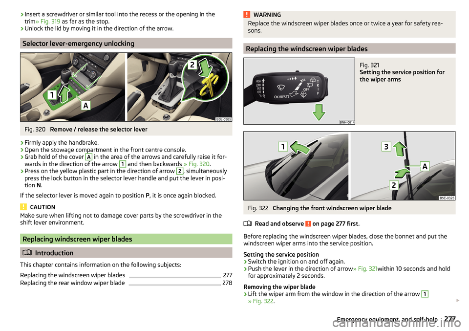
Selector lever-emergency unlocking
Fig. 320
Remove / release the selector lever
›
Firmly apply the handbrake.
›
Open the stowage compartment in the front centre console.
›
Grab hold of the cover
A
in the area of the arrows and carefully raise it for-
wards in the direction of the arrow
1
and then backwards » Fig. 320.
›
Press on the yellow plastic part in the direction of arrow
2
, simultaneously
press the lock button in the selector lever handle and put the lever in posi-
tion N.
If the selector lever is moved again to position P, it is once again blocked.
CAUTION
Make sure when lifting not to damage cover parts by the screwdriver in the
shift lever environment.
Replacing windscreen wiper blades
Introduction
This chapter contains information on the following subjects:
Replacing the windscreen wiper blades
277
Replacing the rear window wiper blade
278WARNINGReplace the windscreen wiper blades once or twice a year for safety rea-
sons.
Replacing the windscreen wiper blades
Fig. 321
Setting the service position for
the wiper arms
Fig. 322
Changing the front windscreen wiper blade
Read and observe
on page 277 first.
Before replacing the windscreen wiper blades, close the bonnet and put the windscreen wiper arms into the service position.
Setting the service position
›
Switch the ignition on and off again.
›
Push the lever in the direction of arrow » Fig. 321within 10 seconds and hold
for approximately 2 seconds.
Removing the wiper blade
›
Lift the wiper arm from the window in the direction of the arrow
1
» Fig. 322 .
277Emergency equipment, and self-help
Page 280 of 324

›Tilt the wiper blade to the stop in the same direction.›Grip the wiper arm and press securing latch A down in the direction of arrow2
.
›
Remove the wiper blade in the direction of the arrow
3
.
Attaching the windscreen wiper blade
›
Slide the windscreen wiper blade in the opposite direction to arrow
3
until it
locks into place. Check that the windscreen wiper blade is correctly attached.
›
Fold the windscreen wiper arm back to the windscreen.
›
Turn on the ignition and press the lever in the direction of the arrow
» Fig. 321 .
The windscreen wiper arms move into the home position.
Replacing the rear window wiper blade
Fig. 323
Changing the rear window wiper blade
Read and observe
on page 277 first.
Removing the wiper blade
›
Lift the wiper arm from the window in the direction of the arrow
1
» Fig. 323 .
›
Tilt the wiper blade to the stop in the same direction.
›
Grip the wiper arm and press securing latch
A
down in the direction of arrow
2
.
›
Remove the wiper blade in the direction of the arrow
3
.
Attaching the windscreen wiper blade
›
Slide the windscreen wiper blade in the opposite direction to arrow
3
until it
locks into place. Check that the windscreen wiper blade is correctly attached.
›
Fold the windscreen wiper arm back to the windscreen.
Fuses and light bulbs
Fuses
Introduction
Fig. 324
Blown fuse
This chapter contains information on the following subjects:
Fuses in the dashboard - LHD
279
Fuses in the dashboard - RHD
279
Fuse assignment in the dashboard
280
Fuses in the engine compartment
281
Fuse assignment in engine compartment
281
Individual electrical circuits are protected by fuses. A blown fuse is recognisa-
ble from the melted-through metal strip » Fig. 324.
WARNINGAlways read and observe the warnings before completing any work in the
engine compartment » page 252.
CAUTION
■
Replace the faulty fuse with a new one of the same amperage.■If a newly inserted fuse again blows after a short time, then seek assistance
from a specialist garage.■
“Do not repair” the fuses and do not replace them with stronger fuses -
There is a risk of fire and damage to another electrical system.
Note
■ We recommend always carrying replacement fuses in the vehicle.■There can be several power consuming devices for one fuse. Multiple fuses
may exist for a single power consuming device.278Do-it-yourself
Page 283 of 324
No.Consumer50Opening the boot lid51Multi-function unit for taxi vehicles52Voltage stabiliser for taxi vehicles53Rear window heating
Fuses in the engine compartment
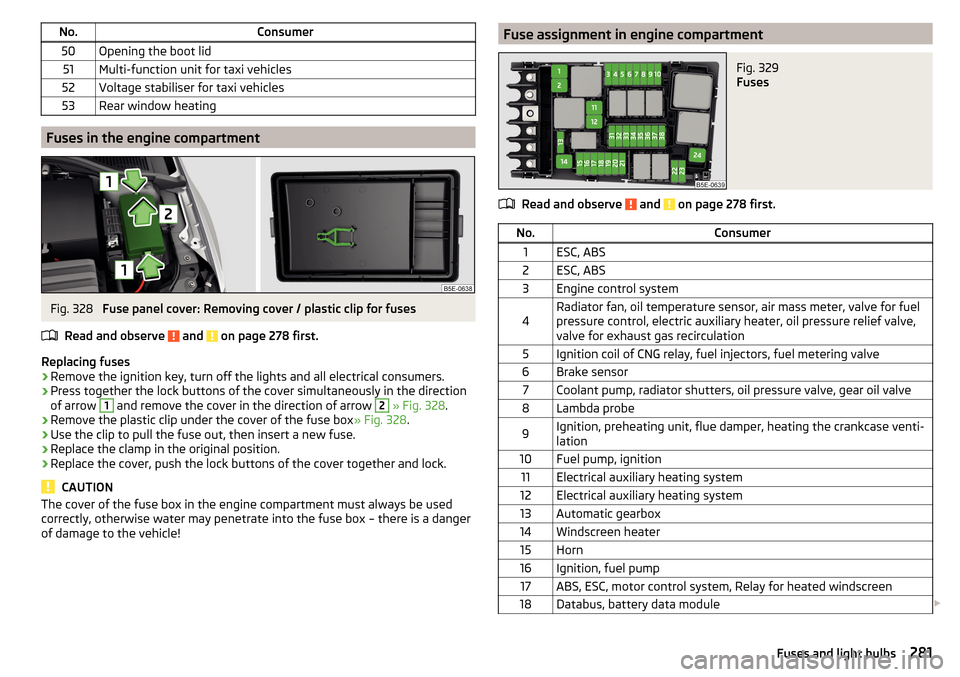
Fig. 328
Fuse panel cover: Removing cover / plastic clip for fuses
Read and observe
and on page 278 first.
Replacing fuses
›
Remove the ignition key, turn off the lights and all electrical consumers.
›
Press together the lock buttons of the cover simultaneously in the direction
of arrow
1
and remove the cover in the direction of arrow
2
» Fig. 328 .
›
Remove the plastic clip under the cover of the fuse box » Fig. 328.
›
Use the clip to pull the fuse out, then insert a new fuse.
›
Replace the clamp in the original position.
›
Replace the cover, push the lock buttons of the cover together and lock.
CAUTION
The cover of the fuse box in the engine compartment must always be used
correctly, otherwise water may penetrate into the fuse box – there is a danger
of damage to the vehicle!Fuse assignment in engine compartmentFig. 329
Fuses
Read and observe and on page 278 first.
No.Consumer1ESC, ABS2ESC, ABS3Engine control system4Radiator fan, oil temperature sensor, air mass meter, valve for fuel
pressure control, electric auxiliary heater, oil pressure relief valve,
valve for exhaust gas recirculation5Ignition coil of CNG relay, fuel injectors, fuel metering valve6Brake sensor7Coolant pump, radiator shutters, oil pressure valve, gear oil valve8Lambda probe9Ignition, preheating unit, flue damper, heating the crankcase venti-
lation10Fuel pump, ignition11Electrical auxiliary heating system12Electrical auxiliary heating system13Automatic gearbox14Windscreen heater15Horn16Ignition, fuel pump17ABS, ESC, motor control system, Relay for heated windscreen18Databus, battery data module 281Fuses and light bulbs
Page 284 of 324
No.Consumer19Windscreen wipers20Anti-theft alarm21Windscreen heater22Engine control system, voltage stabilizer for taxi vehicles23Starter24Electrical auxiliary heating system31Vacuum pump32Not assigned33Not assigned34All-wheel drive35Not assigned36Not assigned37Aux. heating38Not assigned
Bulbs
Introduction
This chapter contains information on the following subjects:
Bulb arrangement in the front headlights
283
Replacing the bulb for the side light (Halogen headlights)
283
Changing the bulb for main beam, separate daytime running lights, and
parking light
283
Replacing the bulb for the side light (Xenon headlights)
284
Change bulb for fog lights switch - Variant 1
284
Change bulb for fog lights switch - Variant 2
285
Changing the bulb for the licence plate light
285
Removing/installing tail light
286
Replacing the bulbs in the tail lamp assembly - Variant 1
286
Replacing the bulbs in the tail lamp assembly - Variant 2
287
We recommend having bulbs replaced by a specialist garage or seeking other
expert help in the event of any uncertainties.
▶ Switch off the ignition and all of the lights before replacing a bulb.
▶ Faulty bulbs must only be replaced with the same type of bulbs. The designa-
tion is located on the light socket or the glass bulb.
We recommend having the headlight settings checked by a specialist garage after replacing a bulb in the low, high or fog beam.
In the case of failure of a Xenon gas discharge bulb or an LED diode, visit a
specialist garage.WARNING■ Always read and observe the warnings before completing any work in the
engine compartment » page 252.■
Accidents can be caused if the road in front of the vehicle is not suffi-
ciently illuminated and the vehicle cannot or can only be seen with difficul-
ty by other road users.
■
Bulbs H7 H8 and H15 are pressurised and may burst when changing the
bulb - risk of injury! We therefore recommended wearing gloves and safety
glasses when changing a bulb.
■
Do not carry out any work on the Xenon gas discharge lamps - risk of
death!
CAUTION
Do not take hold of the glass bulb with naked fingers (even the smallest
amount of dirt reduces the working life of the light bulb). Use a clean cloth,
napkin, or similar.
Note
■ This Owner's Manual only describes the replacement of bulbs where it is pos-
sible to replace the bulbs on your own without any complications arising. Other
bulbs must be replaced by a specialist garage.■
We recommend that a box of replacement bulbs always be carried in the ve-
hicle.
282Do-it-yourself
Page 286 of 324
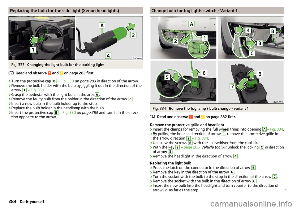
Replacing the bulb for the side light (Xenon headlights)Fig. 333
Changing the light bulb for the parking light
Read and observe
and on page 282 first.
›
Turn the protective cap
B
» Fig. 330 on page 283 in direction of the arrow.
›
Remove the bulb holder with the bulb by jiggling it out in the direction of the
arrow
1
» Fig. 333 .
›
Grasp the pedestal with the light bulb in the area
A
.
›
Remove the faulty bulb from the holder in the direction of the arrow
2
.
›
Insert a new bulb in the bulb holder up to the stop.
›
Replace the bulb holder in the headlamp with the bulb.
›
Insert the protective cap
B
» Fig. 330 on page 283 and turn it in the direc-
tion opposite to the arrow.
Change bulb for fog lights switch - Variant 1Fig. 334
Remove the fog lamp / bulb change - variant 1
Read and observe
and on page 282 first.
Remove the protective grille and headlight
›
Insert the clamps for removing the full wheel trims into opening
A
» Fig. 334 .
›
By pulling the hook in direction of arrow
1
remove the protective grille in
the arrow direction
2
» Fig. 334 .
›
Unscrew the screws
B
with the screwdriver from the tool kit.
›
With the key
2
» page 266 , Vehicle tool kit unlock the locking
C
in direction
of arrow
3
.
›
Remove the headlight in the direction of arrow
4
.
Replacing the light bulb
›
Press the latch on the connector in the direction of arrow
5
.
›
Remove the key in the direction of the arrow
6
.
›
Turn the socket with the bulb to the stop in the direction of the arrow
7
.
›
Remove the socket with the bulb in the direction of arrow
8
.
›
Insert the new bulb into the headlight and turn counter to the direction of
arrow
7
as far as the stop.
284Do-it-yourself
Page 287 of 324
›Fit the connector.
Refit the headlight and grille›
Replace the fog light by inserting it in the opposite direction of the arrow
4
» Fig. 334 and tighten.
›
Insert the guard and push it gently until it locks into place.
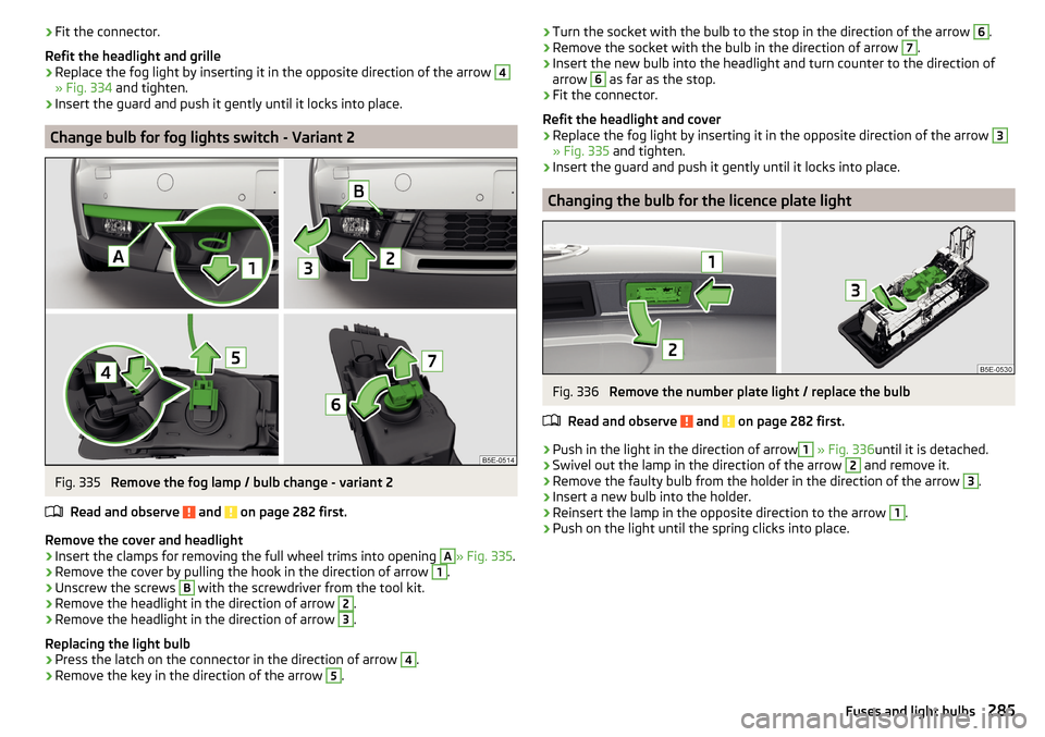
Change bulb for fog lights switch - Variant 2
Fig. 335
Remove the fog lamp / bulb change - variant 2
Read and observe
and on page 282 first.
Remove the cover and headlight
›
Insert the clamps for removing the full wheel trims into opening
A
» Fig. 335 .
›
Remove the cover by pulling the hook in the direction of arrow
1
.
›
Unscrew the screws
B
with the screwdriver from the tool kit.
›
Remove the headlight in the direction of arrow
2
.
›
Remove the headlight in the direction of arrow
3
.
Replacing the light bulb
›
Press the latch on the connector in the direction of arrow
4
.
›
Remove the key in the direction of the arrow
5
.
› Turn the socket with the bulb to the stop in the direction of the arrow 6.›Remove the socket with the bulb in the direction of arrow 7.›
Insert the new bulb into the headlight and turn counter to the direction of
arrow
6
as far as the stop.
›
Fit the connector.
Refit the headlight and cover
›
Replace the fog light by inserting it in the opposite direction of the arrow
3
» Fig. 335 and tighten.
›
Insert the guard and push it gently until it locks into place.
Changing the bulb for the licence plate light
Fig. 336
Remove the number plate light / replace the bulb
Read and observe
and on page 282 first.
›
Push in the light in the direction of arrow
1
» Fig. 336 until it is detached.
›
Swivel out the lamp in the direction of the arrow
2
and remove it.
›
Remove the faulty bulb from the holder in the direction of the arrow
3
.
›
Insert a new bulb into the holder.
›
Reinsert the lamp in the opposite direction to the arrow
1
.
›
Push on the light until the spring clicks into place.
285Fuses and light bulbs
Page 288 of 324

Removing/installing tail lightFig. 337
Remove light / pull out connector
Read and observe
and on page 282 first.
Removing
›
Open the boot lid.
›
Insert the clamps for removing the full wheel trims into opening
A
1)
» Fig. 337 .
›
Remove the cover by pulling the hook in the direction of arrow
1
.
›
Unscrew the screws
B
with the key from the tool kit.
›
Hold the light and carefully remove in the direction of arrow
2
.
›
Press the latches on the connector 2)
in the direction of arrow
3
.
›
Carefully remove the connector from the tail lamp assembly in the direction
of the arrow
4
.
Fitting
›
Insert the connector into the light and lock it securely.
› Insert the lamp with the pin A
» Fig. 338 on page 286 into the recesses C» Fig. 337 in the body.›
Carefully push the cover in » .
›
Screw the tail lamp into place and install the cover. The cover must engage
securely.
›
Shut the boot lid.
CAUTION
■ Ensure that the cable bundle does not become stuck between the body and
the lamp when it is being refitted – or there is a risk of damage to the electrical
installation and risk of water ingress.■
If you are not sure whether the cable bundle has become pinched, we recom-
mend that you have the light connection checked by a specialist garage.
■
Ensure that the vehicle paintwork and the tail lamp are not damaged when
removing and installing the tail lamp.
Replacing the bulbs in the tail lamp assembly - Variant 1
Fig. 338
Outer part of the light: Basic light/light with LED diodes
1)
The position of the opening may vary depending on the vehicle model.
2)
The design of the plug can vary depending on the vehicle equipment.
286Do-it-yourself
Page 306 of 324
Digital Service Plan244
Dipped beam64
Dipstick256
display natural gas supply
31
Petrol / diesel storage31
Display Cardinal points
41
Coolant temperature31
Gear changes42
In the instrument cluster41
Service intervals48
Display MAXI DOT46
Disposal Acceptance and recycling of used vehicles
242
Distance warning219
Warning light40
Diverting calls126
Door Child safety lock
54
Emergency locking276
Emergency locking of the driver's door276
Opening/ Closing54
Door warning41
double hooks96
Drive Driving through water
198
DriveGreen197
Driving Emissions
291
Fuel consumption291
Maximum speed296
through water198
Driving data Show
45
Driving mode221
Adaptive Chassis Control (DCC)221
Comfort222
Eco221
Individual222
Individual mode settings223
Mode selection and Infotainment display223
Normal222
Offroad222
Sports222
Driving Mode Selection221
DSR202
DVD139
DVD video Compatible sources
146
Supported file formats146
Dynamic Road Sign Display Additional display
228
Operation227
Dynamic route switch on / off
186
E
Economical driving
197
ECO TIP41
Eco tips41
Edit route181
EDS201
Electrical boot lid set the top position of the lid
58
Electric boot lid Force limiter
57
Manual operation57
Open/close58
Electric power windows59, 61
Malfunctions61
Electric tailgate Malfunctions
58
Electric Windows Button in driver’s door’
60
Electronic Differential Lock (EDL, XDS)201
Electronic immobiliser188
Elevation169
emergency Jump-starting272
Starting the engine / stopping at the push of a button
190
Emergency Hazard warning light system
68
Jump-starting272
Lever-release277
Starting the engine / stopping the push of a button
189
Towing the using the tow hitch275
Towing the vehicle273
Tyre repair270
Unlocking/locking the door276
Unlocking / locking the door276
Emergency call157
Emergency equipment Fire extinguisher
265
First aid kit265
Jack266
Reflective vest265
Vehicle tool kit266
Warning triangle265
Emergency spare Removing / stowing
267
Emission control system35
Emissions291
Engine Information messages
38
Run in196
Engine compartment252
Brake fluid257
Coolant256
Engine oil255
Overview254
Vehicle battery258
Windscreen washer fluid254
Engine drag torque control (MSR)201
Engine number288
304Index
Page 313 of 324
Removing thebar ball, Step 1233
bar ball, Step 2234
Repairs and technical alterations240
Replace Battery
275
Replacing Bulbs
282
Fuses278
Windscreen wiper blades277
Restart Infotainment117
restaurant173
Rev counter30
Reversing camera207
Function surfaces208
Operation208
Orientation lines208
Rims260
Road sign178
Roller blind Luggage compartment cover
98
Roof Weight
103
Roof rack103
Route179
New route183
Route list183
Store route181
Route calculation179
Trailer towing180
Route details181
Route information181
Route list183
Route options128
rSAP155
Run-in Engine
196
Running inBrake pads191
Tyres260
S
SafeLock
53
Safe removal of the data source124, 130
safety air bag
18
ISOFIX25
Safety12
Child safety22
Child safety seats22
Correct seated position12
Headrests80
ISOFIX25
TOP TETHER26
SAFE, SAFELOCK See SafeLock
53
Save station135
Saving electrical energy197
Saving fuel197
Screen see Infotainment screen
115
Screen display116
SD card140
Safe removal130
Search for car park173
Search for destination171
Search for petrol station173
Search for restaurant173
Seat belt height adjustment
16
Warning light37
Seat belts15
Belt tensioners17
fastening and unfastening16
Inertia reels17
Warning light33
Seat electrical adjustment77
Seats Electrical adjustment
77
Folding front passenger seat78
front76
Front armrest79
Headrests80
Heating81
Manually adjusting76
Memory Function of the electrically adjustable seat
77
Rear79
Rear armrest80
Rear seat backrests79
Setting76
Storing in memory of remote control key78
Seats and head restraint76
see Instrument cluster see Instrument cluster
30
Select broadcasting See main menu
133
Select Image Source Images
144
Selector lever194
Selector lever control194
Selector lever lock Warning light
37
Select source Media
137
Select station See main menu
133
Select video source Video DVD
145
service240
Service Service interval display
48
Warning light40
Service Interval243
Service intervals242
Service Plan244
311Index
Page 314 of 324
SettingAuxiliary heating (auxiliary heating and ventila-tion)
109
Headrests80
Mirror74
Positions of the variable loading floor101
Seat belt height16
Seats76
settings Images
126
Infotainment language123, 130
Infotainment screen123, 130
Video DVD126
Settings Additional keyboard languages
123, 130
Advanced settings129
AUX126
Bluetooth124, 126, 131
Codecs126
Configuration wizard118
DAB125, 132
Data connection124
Equalizer122
External device data transfer123
FM125, 131
Fuel options129
Information regarding the version of the navi- gation data
129
infotainment122
Infotainment130
Manage favourites159
Manage memory128
Map128
Media126, 132
Navigation128
Nav. announcements129
Network124
Pin code126
Radio125, 131
Reset to factory settings124, 187
Restore factory settings131
Route options128
SmartLink128
Software update122
Software updates131
Sound122, 130
Sound system122
Subwoofer122
Surround122
System information122, 125, 131
Telephone126, 132
Text messages126
Time and date123, 130
Top speeds129
Units123, 130
Update software125
User profile159
Vehicle187
Voice control124
Volume118
WLAN124
Settings Call126
Setting the Clock
42
Setup122, 130
Show POIs on the map176
SIM card Change PIN code
154
Data connection164
Insert154
PIN code154
Remove154
Sliding/tilting roof Activating operation of the sunshade
63
SmartGate connection using Wi-Fi direct
49
Connection via Wi-Fi49
introductory information48
Password/PIN code change50
Setting50
SmartLink Android Auto166
Apple CarPlay167
Main menu165
MirrorLink®167
Set to128
SMS161
New161
Operation161
Received162
Snow chains263
sockets 12-volt power socket in the luggage compart- ment
90
12-volt socket in the interior90
Sockets 230 V
90
Software update122
Software Update125
Software updates131
Sound122, 130
Sound system122
Spare wheel262
Removing / stowing267
Speed limitations180
Speed symbol263
Split screen Audio
171
Compass171
Manoeuvre171
Map171
Menus171
Most frequent routes171
Satellite data171
Turn on/off171
Waypoint tour171
Spoiler241
SSID124
Stabilisation system200
Stability Control (ESC)200
312Index