windscreen SKODA OCTAVIA 2016 3.G / (5E) Owner's Guide
[x] Cancel search | Manufacturer: SKODA, Model Year: 2016, Model line: OCTAVIA, Model: SKODA OCTAVIA 2016 3.G / (5E)Pages: 324, PDF Size: 48.85 MB
Page 248 of 324
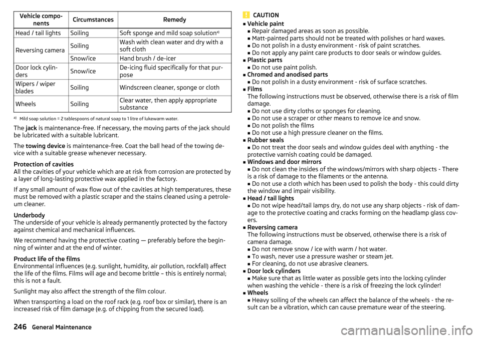
Vehicle compo-nentsCircumstancesRemedyHead / tail lightsSoilingSoft sponge and mild soap solution a)
Reversing cameraSoilingWash with clean water and dry with a
soft clothSnow/iceHand brush / de-icerDoor lock cylin-
dersSnow/iceDe-icing fluid specifically for that pur-
poseWipers / wiper
bladesSoilingWindscreen cleaner, sponge or clothWheelsSoilingClear water, then apply appropriate
substancea)
Mild soap solution = 2 tablespoons of natural soap to 1 litre of lukewarm water.
The jack is maintenance-free. If necessary, the moving parts of the jack should
be lubricated with a suitable lubricant.
The towing device is maintenance-free. Coat the ball head of the towing de-
vice with a suitable grease whenever necessary.
Protection of cavities
All the cavities of your vehicle which are at risk from corrosion are protected by
a layer of long-lasting protective wax applied in the factory.
If any small amount of wax flow out of the cavities at high temperatures, these
must be removed with a plastic scraper and the stains cleaned using a petrole-
um cleaner.
Underbody
The underside of your vehicle is already permanently protected by the factory
against chemical and mechanical influences.
We recommend having the protective coating — preferably before the begin-
ning of winter and at the end of winter.
Product life of the films
Environmental influences (e.g. sunlight, humidity, air pollution, rockfall) affect
the life of the films. Films will age and become brittle – this is entirely normal;
this is not a fault.
Sunlight may also affect the strength of the film colour.
When transporting a load on the roof rack (e.g. roof box or similar), there is an
increased risk of film damage (e.g. of chipping from the secured load).
CAUTION■ Vehicle paint
■ Repair damaged areas as soon as possible.
■ Matt-painted parts should not be treated with polishes or hard waxes.
■ Do not polish in a dusty environment - risk of paint scratches.
■ Do not apply any paint care products to door seals or window guides.■
Plastic parts
■ Do not use paint polish.
■
Chromed and anodised parts
■ Do not polish in a dusty environment - risk of surface scratches.
■
Films
The following instructions must be observed, otherwise there is a risk of film
damage. ■ Do not use dirty cloths or sponges for cleaning.
■ Do not use a scraper or other means to remove ice and snow.
■ Do not polish the films
■ Do not use a high pressure cleaner on the films.
■
Rubber seals
■ Do not treat the door seals and window guides deal with anything - the
protective varnish coating could be damaged.
■
Windows and door mirrors ■ Do not clean the insides of the windows/mirrors with sharp objects - There
is a risk of damage to the filaments or the antenna. ■ Do not use a cloth which has been used to polish the body - this could dirty
the window and impair visibility.
■
Head / tail lights
■ Do not wipe head/tail lamps dry, do not use any sharp objects - risk of dam-
age to the protective coating and cracks forming on the headlamp glass cov-
ers.
■
Reversing camera
The following instructions must be observed, otherwise there is a risk of
camera damage.
■ Do not remove snow / ice with warm / hot water.
■ To wash, never use a pressure washer or steam jet.
■ For cleaning, do not use abrasive cleaners.
■
Door lock cylinders
■ Make sure that as little water as possible gets into the locking cylinder
when washing the vehicle - there is a risk of freezing the lock cylinder!
■
Wheels
■ Heavy soiling of the wheels can affect the balance of the wheels - the re-
sult can be a vibration, which can cause premature wear of the steering.
246General Maintenance
Page 254 of 324
CNGFig. 289
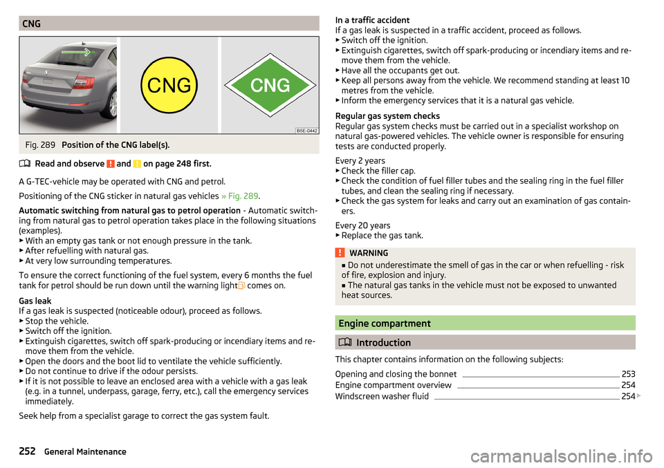
Position of the CNG label(s).
Read and observe
and on page 248 first.
A G-TEC-vehicle may be operated with CNG and petrol.
Positioning of the CNG sticker in natural gas vehicles » Fig. 289.
Automatic switching from natural gas to petrol operation - Automatic switch-
ing from natural gas to petrol operation takes place in the following situations
(examples). ▶ With an empty gas tank or not enough pressure in the tank.
▶ After refuelling with natural gas.
▶ At very low surrounding temperatures.
To ensure the correct functioning of the fuel system, every 6 months the fuel tank for petrol should be run down until the warning light comes on.
Gas leak
If a gas leak is suspected (noticeable odour), proceed as follows. ▶ Stop the vehicle.
▶ Switch off the ignition.
▶ Extinguish cigarettes, switch off spark-producing or incendiary items and re-
move them from the vehicle.
▶ Open the doors and the boot lid to ventilate the vehicle sufficiently.
▶ Do not continue to drive if the odour persists.
▶ If it is not possible to leave an enclosed area with a vehicle with a gas leak
(e.g. in a tunnel, underpass, garage, ferry, etc.), call the emergency services
immediately.
Seek help from a specialist garage to correct the gas system fault.
In a traffic accident
If a gas leak is suspected in a traffic accident, proceed as follows.
▶ Switch off the ignition.
▶ Extinguish cigarettes, switch off spark-producing or incendiary items and re-
move them from the vehicle.
▶ Have all the occupants get out.
▶ Keep all persons away from the vehicle. We recommend standing at least 10
metres from the vehicle.
▶ Inform the emergency services that it is a natural gas vehicle.
Regular gas system checks
Regular gas system checks must be carried out in a specialist workshop on
natural gas-powered vehicles. The vehicle owner is responsible for ensuring
tests are conducted properly.
Every 2 years ▶ Check the filler cap.
▶ Check the condition of fuel filler tubes and the sealing ring in the fuel filler
tubes, and clean the sealing ring if necessary.
▶ Check the gas system for leaks and carry out an examination of gas contain-
ers.
Every 20 years ▶ Replace the gas tank.WARNING■ Do not underestimate the smell of gas in the car or when refuelling - risk
of fire, explosion and injury.■
The natural gas tanks in the vehicle must not be exposed to unwanted
heat sources.
Engine compartment
Introduction
This chapter contains information on the following subjects:
Opening and closing the bonnet
253
Engine compartment overview
254
Windscreen washer fluid
254
252General Maintenance
Page 255 of 324
WARNINGNever cover the engine with additional insulation material (e.g. with a blan-
ket) – risk of fire!WARNINGWhen working in the engine compartment, the following instructions must
be observed - otherwise risk of injury or fire. The engine compartment of
your car is a hazardous area!WARNINGInstructions before beginning work in the engine compartment■Stop the engine and remove the ignition key, on vehicles with the KESSY
system, open the driver's door.■
Firmly apply the handbrake.
■
For vehicles with manual transmission the lever into the neutral position.
For vehicles with automatic transmission , place the selector lever in the P
position.
■
Allow the engine to cool.
■
Never open the bonnet if you can see steam or coolant flowing out of the
engine compartment – risk of scalding! Wait until the steam or coolant has
stopped escaping.
WARNINGInformation for working in the engine compartment■Keep everyone away from the engine compartment.■
Do not touch any hot engine parts – risk of burns!
■
Never touch the radiator fan. The radiator fan may still turn suddenly
about 10 minutes after switching off the ignition!
■
Do not smoke in the vicinity of the engine and avoid the use of open
flames or sparks.
■
Do not leave any items (e.g. cloths or tools) in the engine compartment.
This presents a fire hazard and the risk of engine damage.
■
Read the information and warning instructions on the fluid containers.
WARNINGInformation for working in the engine compartment with the engine run-
ning■
If it is necessary to work on the engine with the engine running, beware
of rotating engine parts and electrical plants - There is a risk to life!
■
Never touch the electric wiring on the ignition system.
■
Avoid short circuits in the electrical system, particularly on the vehicle's
battery.
CAUTION
Only refill using fluids with the proper specification - There is risk of damage to
the vehicle!
Note
■ Fluids with the proper specifications can be purchased from the ŠKODA Origi-
nal Accessories or from the ŠKODA Genuine Parts ranges.■
We recommend you have the operating fluids replaced by a specialist garage.
Opening and closing the bonnet
Fig. 290
Open the bonnet
Read and observe
and on page 253 first.
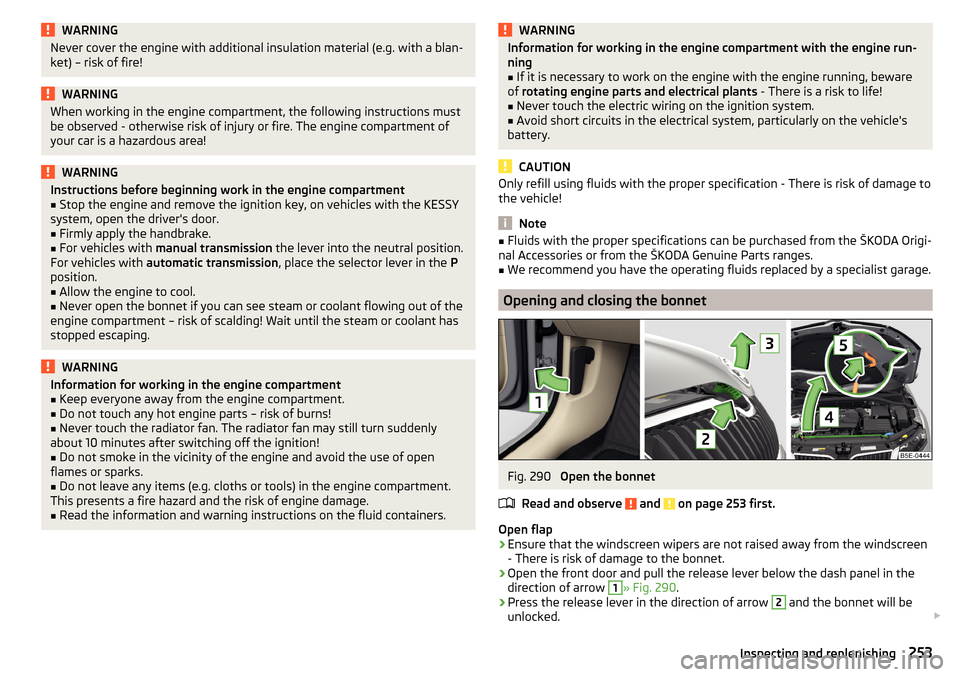
Open flap
›
Ensure that the windscreen wipers are not raised away from the windscreen
- There is risk of damage to the bonnet.
›
Open the front door and pull the release lever below the dash panel in the
direction of arrow
1
» Fig. 290 .
›
Press the release lever in the direction of arrow
2
and the bonnet will be
unlocked.
253Inspecting and replenishing
Page 256 of 324
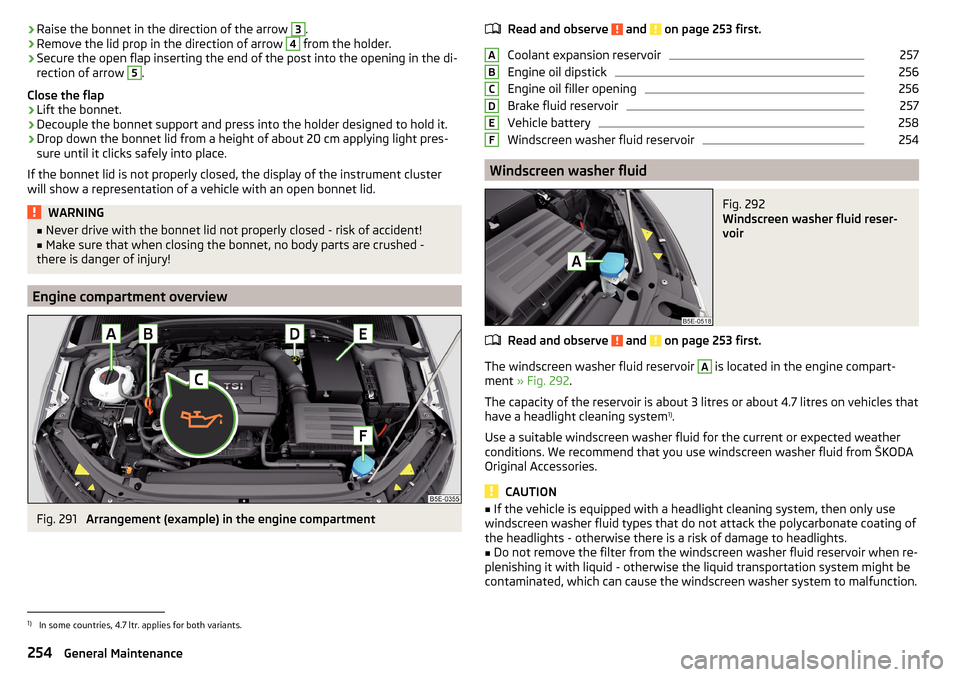
›Raise the bonnet in the direction of the arrow 3.›Remove the lid prop in the direction of arrow 4 from the holder.›
Secure the open flap inserting the end of the post into the opening in the di-
rection of arrow
5
.
Close the flap
›
Lift the bonnet.
›
Decouple the bonnet support and press into the holder designed to hold it.
›
Drop down the bonnet lid from a height of about 20 cm applying light pres-
sure until it clicks safely into place.
If the bonnet lid is not properly closed, the display of the instrument cluster will show a representation of a vehicle with an open bonnet lid.
WARNING■ Never drive with the bonnet lid not properly closed - risk of accident!■Make sure that when closing the bonnet, no body parts are crushed -
there is danger of injury!
Engine compartment overview
Fig. 291
Arrangement (example) in the engine compartment
Read and observe and on page 253 first.
Coolant expansion reservoir
257
Engine oil dipstick
256
Engine oil filler opening
256
Brake fluid reservoir
257
Vehicle battery
258
Windscreen washer fluid reservoir
254
Windscreen washer fluid
Fig. 292
Windscreen washer fluid reser-
voir
Read and observe and on page 253 first.
The windscreen washer fluid reservoir
A
is located in the engine compart-
ment » Fig. 292 .
The capacity of the reservoir is about 3 litres or about 4.7 litres on vehicles that
have a headlight cleaning system 1)
.
Use a suitable windscreen washer fluid for the current or expected weather
conditions. We recommend that you use windscreen washer fluid from ŠKODA
Original Accessories.
CAUTION
■ If the vehicle is equipped with a headlight cleaning system, then only use
windscreen washer fluid types that do not attack the polycarbonate coating of
the headlights - otherwise there is a risk of damage to headlights.■
Do not remove the filter from the windscreen washer fluid reservoir when re-
plenishing it with liquid - otherwise the liquid transportation system might be
contaminated, which can cause the windscreen washer system to malfunction.
ABCDEF1)
In some countries, 4.7 ltr. applies for both variants.
254General Maintenance
Page 275 of 324
WARNING■Never clamp the jump cable to the negative terminal of the discharged
battery - There is a risk of explosion.■
The non-insulated parts of the terminal clamps must never touch each
other – risk of short circuit!
■
The jump-start cable connected to the positive terminal of the battery
must not come into contact with electrically conducting parts of the vehicle
– risk of short circuit!
■
Position the jump cables so that they cannot be caught in rotating parts
in the engine compartment - danger of injuries and the risk of vehicle dam-
age.
Towing the vehicle
Information about the towing process
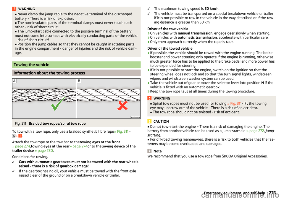
Fig. 311
Braided tow ropes/spiral tow rope
To tow with a tow rope, only use a braided synthetic fibre rope » Fig. 311 -
»
.
Attach the tow rope or the tow bar to the towing eyes at the front
» page 274 ,towing eyes at the rear » page 274or to thetowing device of the
trailer device » page 230 .
Conditions for towing. Cars with automatic gearboxes must not be towed with the rear wheels
raised - there is a risk of gearbox damage!
If the gearbox has no oil, your vehicle must be towed with the front axle
raised clear of the ground or on a breakdown vehicle or trailer.
The maximum towing speed is 50 km/h.
The vehicle must be transported on a special breakdown vehicle or trailer
if it is not possible to tow in the vehicle in the way described or if the tow-
ing distance is greater than 50 km.
Driver of the tow vehicle›
On vehicles with manual transmission , engage gear slowly when starting.
›
On vehicles with automatic transmission , accelerate with particular care.
›
Only then approach correctly when the rope is taut.
Driver of the towed vehicle
›
If possible, the vehicle should be towed with the engine running. The brake
booster and power steering only operate if the engine is running, otherwise
much greater force has to be applied to the brake pedal and more power has
to be expended for steering.
›
If it is not possible to start the engine, switch on the ignition so that the
steering wheel does not lock and so that the turn signal lights, windscreen
wipers and windscreen washer system can be used.
›
Take the vehicle out of gear or move the selector lever into position N if the
vehicle is fitted with an automatic gearbox.
›
Keep the tow rope taut at all times during the towing procedure.
WARNING■ Spiral tow ropes must not be used for towing » Fig. 311- , the towing
eye may unscrew out of the vehicle - There is a risk of an accident.■
The tow rope should not be twisted - risk of accident.
CAUTION
■ Do not tow-start the engine – There is a risk of damaging the engine. The
battery from another vehicle can be used as a jump-start aid » page 272, Jump-
starting .■
For off-road towing manoeuvres, there is a risk to both vehicles that the fas-
teners may become overloaded and damaged.
Note
We recommend that you use a tow rope from ŠKODA Original Accessories.273Emergency equipment, and self-help
Page 279 of 324
›Insert a screwdriver or similar tool into the recess or the opening in the
trim » Fig. 319 as far as the stop.›
Unlock the lid by moving it in the direction of the arrow.
Selector lever-emergency unlocking
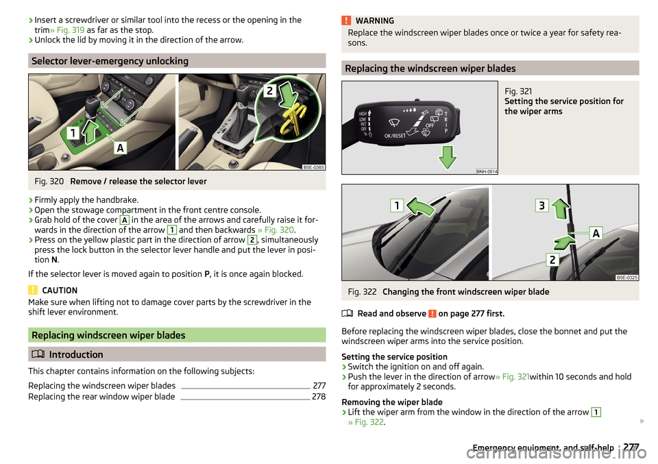
Fig. 320
Remove / release the selector lever
›
Firmly apply the handbrake.
›
Open the stowage compartment in the front centre console.
›
Grab hold of the cover
A
in the area of the arrows and carefully raise it for-
wards in the direction of the arrow
1
and then backwards » Fig. 320.
›
Press on the yellow plastic part in the direction of arrow
2
, simultaneously
press the lock button in the selector lever handle and put the lever in posi-
tion N.
If the selector lever is moved again to position P, it is once again blocked.
CAUTION
Make sure when lifting not to damage cover parts by the screwdriver in the
shift lever environment.
Replacing windscreen wiper blades
Introduction
This chapter contains information on the following subjects:
Replacing the windscreen wiper blades
277
Replacing the rear window wiper blade
278WARNINGReplace the windscreen wiper blades once or twice a year for safety rea-
sons.
Replacing the windscreen wiper blades
Fig. 321
Setting the service position for
the wiper arms
Fig. 322
Changing the front windscreen wiper blade
Read and observe
on page 277 first.
Before replacing the windscreen wiper blades, close the bonnet and put the windscreen wiper arms into the service position.
Setting the service position
›
Switch the ignition on and off again.
›
Push the lever in the direction of arrow » Fig. 321within 10 seconds and hold
for approximately 2 seconds.
Removing the wiper blade
›
Lift the wiper arm from the window in the direction of the arrow
1
» Fig. 322 .
277Emergency equipment, and self-help
Page 280 of 324

›Tilt the wiper blade to the stop in the same direction.›Grip the wiper arm and press securing latch A down in the direction of arrow2
.
›
Remove the wiper blade in the direction of the arrow
3
.
Attaching the windscreen wiper blade
›
Slide the windscreen wiper blade in the opposite direction to arrow
3
until it
locks into place. Check that the windscreen wiper blade is correctly attached.
›
Fold the windscreen wiper arm back to the windscreen.
›
Turn on the ignition and press the lever in the direction of the arrow
» Fig. 321 .
The windscreen wiper arms move into the home position.
Replacing the rear window wiper blade
Fig. 323
Changing the rear window wiper blade
Read and observe
on page 277 first.
Removing the wiper blade
›
Lift the wiper arm from the window in the direction of the arrow
1
» Fig. 323 .
›
Tilt the wiper blade to the stop in the same direction.
›
Grip the wiper arm and press securing latch
A
down in the direction of arrow
2
.
›
Remove the wiper blade in the direction of the arrow
3
.
Attaching the windscreen wiper blade
›
Slide the windscreen wiper blade in the opposite direction to arrow
3
until it
locks into place. Check that the windscreen wiper blade is correctly attached.
›
Fold the windscreen wiper arm back to the windscreen.
Fuses and light bulbs
Fuses
Introduction
Fig. 324
Blown fuse
This chapter contains information on the following subjects:
Fuses in the dashboard - LHD
279
Fuses in the dashboard - RHD
279
Fuse assignment in the dashboard
280
Fuses in the engine compartment
281
Fuse assignment in engine compartment
281
Individual electrical circuits are protected by fuses. A blown fuse is recognisa-
ble from the melted-through metal strip » Fig. 324.
WARNINGAlways read and observe the warnings before completing any work in the
engine compartment » page 252.
CAUTION
■
Replace the faulty fuse with a new one of the same amperage.■If a newly inserted fuse again blows after a short time, then seek assistance
from a specialist garage.■
“Do not repair” the fuses and do not replace them with stronger fuses -
There is a risk of fire and damage to another electrical system.
Note
■ We recommend always carrying replacement fuses in the vehicle.■There can be several power consuming devices for one fuse. Multiple fuses
may exist for a single power consuming device.278Do-it-yourself
Page 283 of 324
No.Consumer50Opening the boot lid51Multi-function unit for taxi vehicles52Voltage stabiliser for taxi vehicles53Rear window heating
Fuses in the engine compartment
Fig. 328
Fuse panel cover: Removing cover / plastic clip for fuses
Read and observe
and on page 278 first.
Replacing fuses
›
Remove the ignition key, turn off the lights and all electrical consumers.
›
Press together the lock buttons of the cover simultaneously in the direction
of arrow
1
and remove the cover in the direction of arrow
2
» Fig. 328 .
›
Remove the plastic clip under the cover of the fuse box » Fig. 328.
›
Use the clip to pull the fuse out, then insert a new fuse.
›
Replace the clamp in the original position.
›
Replace the cover, push the lock buttons of the cover together and lock.
CAUTION
The cover of the fuse box in the engine compartment must always be used
correctly, otherwise water may penetrate into the fuse box – there is a danger
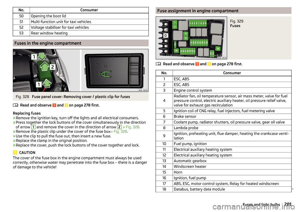
of damage to the vehicle!Fuse assignment in engine compartmentFig. 329
Fuses
Read and observe and on page 278 first.
No.Consumer1ESC, ABS2ESC, ABS3Engine control system4Radiator fan, oil temperature sensor, air mass meter, valve for fuel
pressure control, electric auxiliary heater, oil pressure relief valve,
valve for exhaust gas recirculation5Ignition coil of CNG relay, fuel injectors, fuel metering valve6Brake sensor7Coolant pump, radiator shutters, oil pressure valve, gear oil valve8Lambda probe9Ignition, preheating unit, flue damper, heating the crankcase venti-
lation10Fuel pump, ignition11Electrical auxiliary heating system12Electrical auxiliary heating system13Automatic gearbox14Windscreen heater15Horn16Ignition, fuel pump17ABS, ESC, motor control system, Relay for heated windscreen18Databus, battery data module 281Fuses and light bulbs
Page 284 of 324
No.Consumer19Windscreen wipers20Anti-theft alarm21Windscreen heater22Engine control system, voltage stabilizer for taxi vehicles23Starter24Electrical auxiliary heating system31Vacuum pump32Not assigned33Not assigned34All-wheel drive35Not assigned36Not assigned37Aux. heating38Not assigned
Bulbs
Introduction
This chapter contains information on the following subjects:
Bulb arrangement in the front headlights
283
Replacing the bulb for the side light (Halogen headlights)
283
Changing the bulb for main beam, separate daytime running lights, and
parking light
283
Replacing the bulb for the side light (Xenon headlights)
284
Change bulb for fog lights switch - Variant 1
284
Change bulb for fog lights switch - Variant 2
285
Changing the bulb for the licence plate light
285
Removing/installing tail light
286
Replacing the bulbs in the tail lamp assembly - Variant 1
286
Replacing the bulbs in the tail lamp assembly - Variant 2
287
We recommend having bulbs replaced by a specialist garage or seeking other
expert help in the event of any uncertainties.
▶ Switch off the ignition and all of the lights before replacing a bulb.
▶ Faulty bulbs must only be replaced with the same type of bulbs. The designa-
tion is located on the light socket or the glass bulb.
We recommend having the headlight settings checked by a specialist garage after replacing a bulb in the low, high or fog beam.
In the case of failure of a Xenon gas discharge bulb or an LED diode, visit a
specialist garage.WARNING■ Always read and observe the warnings before completing any work in the
engine compartment » page 252.■
Accidents can be caused if the road in front of the vehicle is not suffi-
ciently illuminated and the vehicle cannot or can only be seen with difficul-
ty by other road users.
■
Bulbs H7 H8 and H15 are pressurised and may burst when changing the
bulb - risk of injury! We therefore recommended wearing gloves and safety
glasses when changing a bulb.
■
Do not carry out any work on the Xenon gas discharge lamps - risk of
death!
CAUTION
Do not take hold of the glass bulb with naked fingers (even the smallest
amount of dirt reduces the working life of the light bulb). Use a clean cloth,
napkin, or similar.
Note
■ This Owner's Manual only describes the replacement of bulbs where it is pos-
sible to replace the bulbs on your own without any complications arising. Other
bulbs must be replaced by a specialist garage.■
We recommend that a box of replacement bulbs always be carried in the ve-
hicle.
282Do-it-yourself
Page 291 of 324
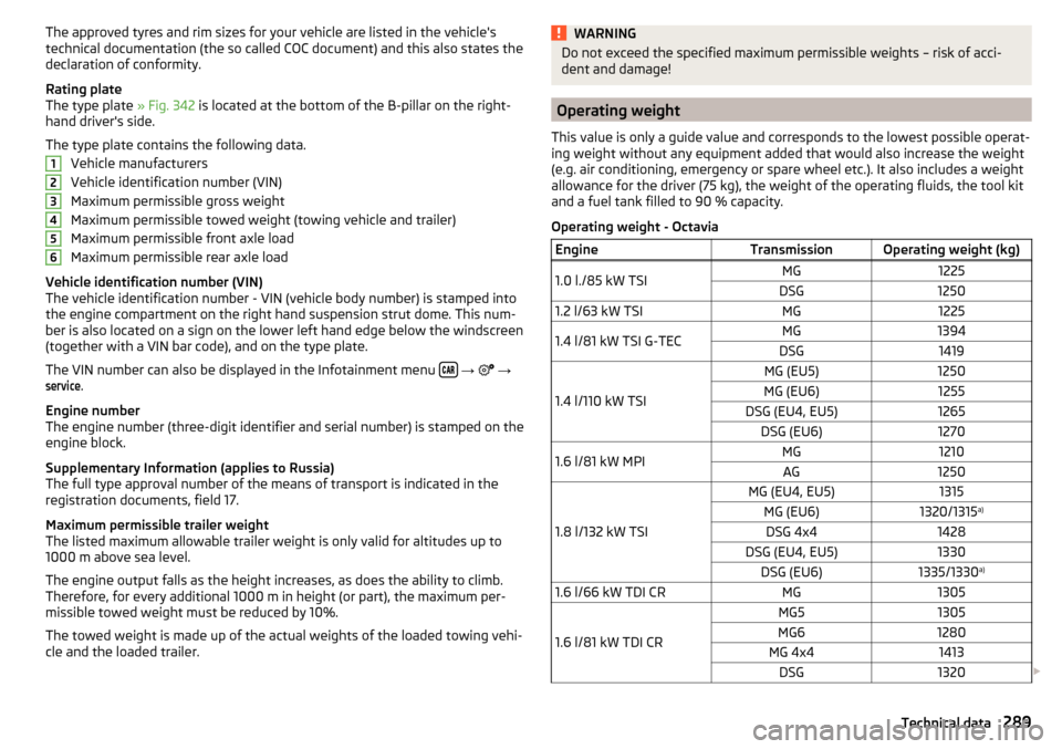
The approved tyres and rim sizes for your vehicle are listed in the vehicle's
technical documentation (the so called COC document) and this also states the
declaration of conformity.
Rating plate
The type plate » Fig. 342 is located at the bottom of the B-pillar on the right-
hand driver's side.
The type plate contains the following data. Vehicle manufacturers
Vehicle identification number (VIN)
Maximum permissible gross weight
Maximum permissible towed weight (towing vehicle and trailer)
Maximum permissible front axle load
Maximum permissible rear axle load
Vehicle identification number (VIN)
The vehicle identification number - VIN (vehicle body number) is stamped into
the engine compartment on the right hand suspension strut dome. This num-
ber is also located on a sign on the lower left hand edge below the windscreen
(together with a VIN bar code), and on the type plate.
The VIN number can also be displayed in the Infotainment menu
→
→
service
.
Engine number
The engine number (three-digit identifier and serial number) is stamped on the
engine block.
Supplementary Information (applies to Russia)
The full type approval number of the means of transport is indicated in the
registration documents, field 17.
Maximum permissible trailer weight
The listed maximum allowable trailer weight is only valid for altitudes up to
1000 m above sea level.
The engine output falls as the height increases, as does the ability to climb.
Therefore, for every additional 1000 m in height (or part), the maximum per-
missible towed weight must be reduced by 10%.
The towed weight is made up of the actual weights of the loaded towing vehi-
cle and the loaded trailer.
123456WARNINGDo not exceed the specified maximum permissible weights – risk of acci-
dent and damage!
Operating weight
This value is only a guide value and corresponds to the lowest possible operat-
ing weight without any equipment added that would also increase the weight
(e.g. air conditioning, emergency or spare wheel etc.). It also includes a weight
allowance for the driver (75 kg), the weight of the operating fluids, the tool kit
and a fuel tank filled to 90 % capacity.
Operating weight - Octavia
EngineTransmissionOperating weight (kg)1.0 l./85 kW TSIMG1225DSG12501.2 l/63 kW TSIMG12251.4 l/81 kW TSI G-TECMG1394DSG1419
1.4 l/110 kW TSI
MG (EU5)1250MG (EU6)1255DSG (EU4, EU5)1265DSG (EU6)12701.6 l/81 kW MPIMG1210AG1250
1.8 l/132 kW TSI
MG (EU4, EU5)1315MG (EU6)1320/1315 a)DSG 4x41428DSG (EU4, EU5)1330DSG (EU6)1335/1330 a)1.6 l/66 kW TDI CRMG1305
1.6 l/81 kW TDI CR
MG51305MG61280MG 4x41413DSG1320
289Technical data