sensor SKODA OCTAVIA TOUR 2009 1.G / (1U) Owner's Manual
[x] Cancel search | Manufacturer: SKODA, Model Year: 2009, Model line: OCTAVIA TOUR, Model: SKODA OCTAVIA TOUR 2009 1.G / (1U)Pages: 226, PDF Size: 13.11 MB
Page 14 of 226
The brief instruction13
Using the system
Safety
Driving Tips
General Maintenance
Breakdown assistance
Technical Data
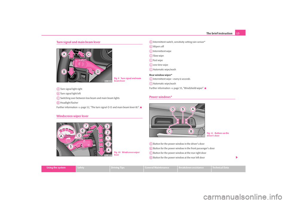
Turn signal and main beam lever Turn signal light right
Turn signal light left
Switching over between low beam and main beam lights
Headlight flasher
Further information ⇒page 52, “The turn signal and main beam lever ”.Windscreen wiper lever
Intermittent switch, sensitivity setting rain sensor*
Wipers off
Intermittent wipe
Slow wipe
Fast wipe
one time wipe
Automatic wipe/wash
Rear window wiper* Intermittent wipe - every 6 seconds
Automatic wipe/wash
Further information ⇒page 55, “Windshield wiper”.Power windows* Button for the power window in the driver's door
Button for the power window in the front passenger's door
Button for the power window at the rear right door
Button for the power window at the rear left door
Fig. 9 Turn signal and main
beam lever
AAABACAD
Fig. 10 Windscreen wiper
lever
AAA0A1A2A3A4A5A6A7
Fig. 11 Buttons on the
driver's door
AAABACAD
s2ig.book Page 13 Monday, November 10, 2008 11:20 AM
Page 27 of 226
Instruments and Indicator/Warning Lights
26If several operational faults of priority 1 exist, the symbols appear one after the
other and are each illuminated for about 2 seconds.Yellow symbols
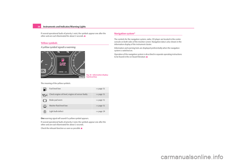
A yellow symbol signals a warning.The meaning of the yellow symbols:
One warning signal will sound if a yellow symbol appears.
If several operational faults of priority 2 exist, the symbols appear one after the
other and are each illuminated for about 2 seconds.
Check the relevant function as soon as possible.
Navigation system*The controls for the navigation system, radi o, CD player are located in the centre
console on both sides of the monitor screen. Navigation data is also shown in the
information display of the instrument cluster.
Information and warning texts are displayed preferentially when the navigation
system is switched on.
Operation of the navigation system is described in separate operating instructions
to be found in the on-board literature.
Fuel level low
⇒ page 31
Check engine oil level, engine oil sensor faulty
⇒page 31
Brake pad worn
⇒page 31
Washer fluid level low
⇒page 31
Light bulb defect
⇒page 29
Fig. 30 Information display:
Fuel level low
s2ig.book Page 26 Monday, November 10, 2008 11:20 AM
Page 33 of 226
Instruments and Indicator/Warning Lights
32Do not continue your journey if for some reason it is not possible under the
conditions prevailing to top up with oil. Keep the engine switched off and obtain
professional assistance from a specialist garage, otherwise it could lead to severe
engine damage.
Do not drive any further if the warning light remains on even if the oil is at the
correct level. Do not run the engine not at idling speed either. Contact the nearest
specialist garage to obtain professional assistance.
The following text will be displayed in the information display*:
STOP! OIL PRESS. STOP MOTOR! SERVICE MANUAL
The warning light
lights up yellow* (oil quantity too low)
If the warning light lights up yellow, there is not the correct quantity of oil in the
engine. Check as soon as possible the oil level or top up ⇒page 165 with engine
oil.
A peep sounds as an additional warning signal.
The following text will be displayed in the information display*:
CHECK OIL LEVEL
When opening the bonnet, the warning light goes out. If no engine oil has been
replenished, the warning light will come on again after driving about 100 km.
The warning light
flashes yellow* (engine oil level sensor faulty)
A fault on the engine oil level sensor is in dicated additionally by an audible signal
and the warning light coming on several times after the ignition has been switched
on.
In this case have the engine inspecte d without delay by a specialist garage.
The following text will be displayed in the information display*: OIL SENSOR WORKSHOP!
WARNING
•
If you must stop for technical reasons, then park the vehicle at a safe
distance from the traffic and switch off the engine and switch on the hazard
warning light system ⇒ page 51.
•
The red oil pressure light
is not an oil level indicator! One should
therefore check the oil level at regular intervals, preferably after every refu-
eling stop.
Open door*
The warning light
comes on, if one or several doors are opened.
The warning light on vehicles fitted with information display comes on when
switching the ignition off. If a door or the boot lid is opened.
The warning light on vehicles fitted with information display goes out after
switching the ignition off.
Antilock brake system (ABS) *
The warning light
shows the functionality of the ABS and the Electronic Differ-
ential Lock (EDL)*.
The warning light comes on for a few seconds after the ignition has been switched
on or when starting the engine. The warnin g light goes out after an automatic check
sequence has been completed.
A fault in the ABS
The system is not functioning properly if the ABS warning light
does not go out
within a few seconds after switching on the ig nition, does not light up at all or lights
up while driving. The vehicle will only be braked by the normal brake system. Visit
a specialist garage as quickly as possible and adjust your style of driving in the
meantime since you will not know how great the damage is.
Further information about ABS ⇒page 137, “Antilock brake system (ABS)*”.
A fault in the entire brake system
If the ABS warning light
comes on together with the brake system warning light
(handbrake must be released), there is a fault not only in the ABS but also in
another part of the brake system ⇒.WARNING (continued)
s2ig.book Page 32 Monday, November 10, 2008 11:20 AM
Page 57 of 226
Lights and Visibility
56
Fast wipe
– Position the lever up into position .
Automatic wipe/wash for windscreen
– Pull the lever towards the steering wheel into the spring-tensioned position , the windscreen wiper and wash system will operate
immediately.
– Release the lever. The windscreen wash system stops and the wiper continues for another 1 - 3 wiper stro kes (depending on the period of
spraying of the windscreen).
Rain sensor*
– Move the lever into position .
– You can set the sensitivity of the sensor individually with switch .
– After switching off the ignition, you must then once again activate the
sensor by moving the lever into position , and then back into posi-
tion .
Wiping the rear window pane*
– Push the lever away from the steering wheel into position - the widescreen wiper will operate every 6 seconds.
Automatic wipe/wash for the rear window pane*
– Push the lever away from the steering wheel into the spring-tensioned position , the windscreen wiper and wash system will operate. As
long as you hold the lever in this position, the wiper and the wash
system operate - spring -tensioned position.
– Letting go of the lever will cause the windscreen wash system to stop and the wiper to continue for anot her 1 - 3 wiper strokes (depending
on the period of spraying of the windscreen). The lever will stay in
position after releasing it . Switching windscreen wipers off
– Move the lever back into its home position .
The windscreen wipers and the windscreen washer system only operate if the igni-
tion is switched on.
The rain sensor* automatically regulates
the break between the individual wiper
strokes depending on the intensity of the rain.
The windscreen washer nozzles are heated* when the ignition is switched on.
Top up with wash liquid ⇒page 174.
WARNING
•
Properly maintained windscreen wi per blades are essential for clear
visibility and safe driving ⇒page 57, “Replacing wiper blades for the wind-
screen wipers”.
•
Do not use the windscreen washer system at low temperatures, without
heating the windscreen beforehand. Otherwise the window cleaner could
freeze on the windscreen and re strict the view to the front.
•
The rain sensor only operates as a support. The driver is not released
from the responsibility to set the function of the windscreen wipers manu-
ally depending on the visibility conditions.Caution
In frosty weather, please first of all check whether the windscreen wiper blades are
not frozen to the windscreen before switching them on. Switching on windscreen
wipers when the blades are frozen to the windscreen may result in damage both to
the blades and the motor of the windscreen wipers!Headlight cleaning system*After each wash cycle of the windscreen an d if the parking lights, low beam light or
main beam light are switched on, the headlights are also cleaned.
A3
A5
A1
AA
A0
A1
A6
A7
A6
A0
s2ig.book Page 56 Monday, November 10, 2008 11:20 AM
Page 92 of 226
Heating and air conditioning system91
Using the system
Safety
Driving Tips
General Maintenance
Breakdown assistance
Technical Data
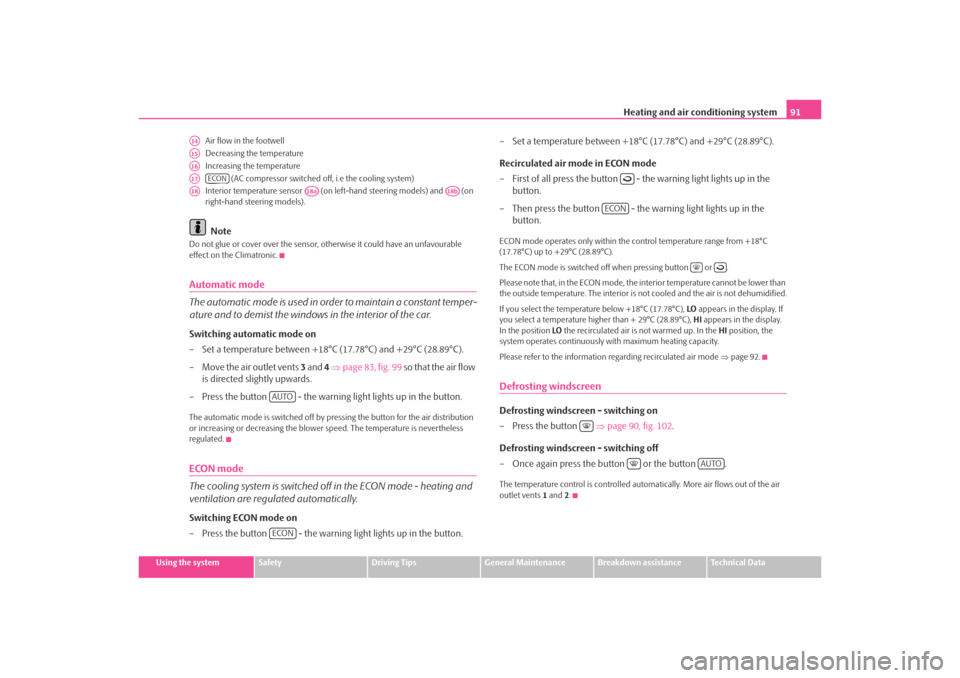
Air flow in the footwell
Decreasing the temperature
Increasing the temperature
(AC compressor switched off, i.e the cooling system)
Interior temperature sensor (on le ft-hand steering models) and (on
right-hand steering models).
Note
Do not glue or cover over the sensor, ot herwise it could have an unfavourable
effect on the Climatronic.Automatic mode
The automatic mode is used in orde r to maintain a constant temper-
ature and to demist the windows in the interior of the car.Switching automatic mode on
– Set a temperature between +18°C (17.78°C) and +29°C (28.89°C).
– Move the air outlet vents 3 and 4 ⇒ page 83, fig. 99 so that the air flow
is directed slightly upwards.
– Press the button - the warning light lights up in the button.The automatic mode is switched off by pr essing the button for the air distribution
or increasing or decreasing the blower speed. The temperature is nevertheless
regulated.ECON mode
The cooling system is switched off in the ECON mode - heating and
ventilation are regulated automatically.Switching ECON mode on
– Press the button - the warning light lights up in the button. – Set a temperature between +18°
C (17.78°C) and +29°C (28.89°C).
Recirculated air mode in ECON mode
– First of all press the button - the warning light lights up in the button.
– Then press the button - the warning light lights up in the button.
ECON mode operates only within the control temperature range from +18°C
(17.78°C) up to +29°C (28.89°C).
The ECON mode is switched off when pressing button or .
Please note that, in the ECON mode, the in terior temperature cannot be lower than
the outside temperature. The interior is not cooled and the air is not dehumidified.
If you select the temperature below +18°C (17.78°C), LO appears in the display. If
you select a temperature higher than + 29°C (28.89°C), HI appears in the display.
In the position LO the recirculated air is not warmed up. In the HI position, the
system operates continuously with maximum heating capacity.
Please refer to the information regarding recirculated air mode ⇒page 92.Defrosting windscreenDefrosting windscreen - switching on
–Press the button ⇒page 90, fig. 102 .
Defrosting windscreen - switching off
– Once again press the button or the button .The temperature control is controlled auto matically. More air flows out of the air
outlet vents 1 and 2.
A14A15A16A17
ECON
A18
A18a
A18b
AUTOECON
ECON
AUTO
s2ig.book Page 91 Monday, November 10, 2008 11:20 AM
Page 99 of 226
Starting-off and Driving
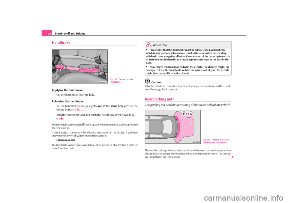
98HandbrakeApplying the handbrake
– Pull the handbrake lever up fully.
Releasing the handbrake
– Pull the handbrake lever up slightly and at the same time press in the
locking button ⇒fig. 107 .
– Hold the button pressed and push the handbrake lever down fully ⇒ .The handbrake warning light
lights up when the handbrake is applied, provided
the ignition is on.
A warning signal sounds and the following text appears in the display* if you have
inadvertently driven off with the handbrake applied:
HANDBRAKE ON
The handbrake warning is activated if you drive at a speed of more than 6 km/h for
more than 3 seconds.
WARNING
•
Please note that the handbrake must be fully released. A handbrake
which is only partially released can re sult in the rear brakes overheating
which will have a negative effect on the operation of the brake system - risk
of accident! In addition this can result in premature wear of the rear brake
pads.
•
Never leave children unattended in the vehicle. The children might, for
example, release the handbrake or take the vehicle out of gear. The vehicle
might then move off - risk of accident!Caution
After the vehicle has come to a stop, first of all apply the handbrake and then addi-
tionally engage the first gear.Rear parking aid*The parking aid provides a warning of obstacles behind the vehicle.The audible parking aid determines the di stance between the rear bumper and an
obstacle located behind the vehicle with the aid of ultrasound sensors. The sensors
are integrated in the rear bumper.
Fig. 107 Centre console:
Handbrake
Fig. 108 Parking aid: Detec-
tion range of rear sensors
s2ig.book Page 98 Monday, November 10, 2008 11:20 AM
Page 100 of 226
Starting-off and Driving99
Using the system
Safety
Driving Tips
General Maintenance
Breakdown assistance
Technical Data
Range of sensors
The clearance warning begins at a distance
of about 160 cm from the obstacle (area
⇒ page 98, fig. 108 ). The interval between the warning signals becomes shorter
as the clearance is reduced.
A continuous tone sounds from a distance of ap prox. 30 cm (area ) - danger
area. You should not reverse any further after this signal sounds!
Activating
The parking aid is activated automatically when reverse gear is engaged and the
ignition is turned on. This is confirmed by a brief acknowledgement signal.
Deactivating
The parking aid is deactivated by removing the reverse gear.
WARNING
•
The parking aid is not a substitute fo r the driver paying proper attention
and it is always the driver's responsibility to take care when parking the
vehicle or carrying out similar manoeuvres.
•
You should therefore satisfy yourself, before reversing, that there is no
small obstacle, such as a rock, thin po st, trailer drawbar etc., behind your
vehicle. Such an obstacle might not be within the range detected by the
sensors.Note
•
The parking aid does not operate if you are towing a trailer (applies to models
which feature a factory-fitted towing device*).
•
If a warning signal sounds for about 3 se conds after switching the ignition on
and engaging reverse gear, and there is no obstacle close to your car, this indicates
a system fault. Have the fault rectified by a specialist workshop.
•
The sensors must be kept clean and free of ice to enable the parking aid to
operate properly.
Cruise control system (CCS)*IntroductionThe cruise control system (CCS) maintains a constant speed, more than 30 km/h
(20 mph), once it has been set, without yo u having to depress the accelerator pedal.
This is only possible within the range wh ich is permitted by the power output and
braking power of the engine. The cruise co ntrol system makes it possible - particu-
larly on long journeys - for you to rest your “accelerator foot”.
WARNING
•
The cruise control system must not, for safety reasons, be used in dense
traffic or on unfavourable road surfaces (such as icy roads, slippery roads or
loose chippings) - risk of accident!
•
In order to prevent unintentional use of the cruise control system,
always switch off the system after use.Note
•
Models fitted with a manual gearbox: Always depress the clutch pedal if you
switch on the cruise control system when the gearbox is in Neutral. Otherwise the
engine can rev up unintentionally.
•
The cruise control system is not able to maintain a constant speed when driving
on steep downhill sections. The weight of the vehicle increases the speed at which
it travels. One should shift down in good time to a lower gear or slow the vehicle
down by applying the foot brake.
AA
AB
s2ig.book Page 99 Monday, November 10, 2008 11:20 AM
Page 134 of 226
Intelligent Technology133
Using the system
Safety
Driving Tips
General Maintenance
Breakdown assistance
Technical Data
Driving TipsIntelligent TechnologyElectronic stability programme (ESP)*GeneralGeneral
The ESP aids you maintain control of your vehicle in situations in borderline driving
situations such as when negotiating a curve too fast. The risk of skidding is reduced
and your car thus offers greater driving stability depending on the conditions of the
road surface. This occurs at all speeds.
The following systems are integrated into the electronic stability programme:•
Electronic Differential Lock (EDL),
•
Traction control system (TCS),
•
Antilock brake system (ABS),
•
Brake Assist. Operating principle
The ESP switches on automatically when the engine is started and then conducts a
self-test. The ESP control unit processes data from the individual systems. It also
processes additional measurement data which are supplied by highly sensitive
sensors: the rotational velocity of the vehi
cle about its vertical axis, the lateral accel-
eration of the vehicle, the brakin g pressure and the steering angle.
The direction which the driver wishes to ta ke is determined based on the steering
angle and the speed of the vehicle and is constantly compared with the actual
behaviour of the vehicle. If differences exis t, such as the car beginning to skid, the
ESP will automatically brake the appropriate wheel.
The car is stabilised again by the forces which take effect when the wheel is braked.
Intervention into the brake system takes place primarily on the outer front wheel of
a vehicle which tends to oversteer (tendency for the rear of the vehicle to break
away) while occurs this is on the inner re ar wheel of a vehicle which tends to under-
steer (tendency to shift out of the curve). This braking control cycle is accompanied
by noises.
The ESP operates in combination with the ABS ⇒page 137, “Antilock brake system
(ABS)*”. If there is a fault in the ABS system, the ESP also does not operate.
The ESP warning light ⇒page 33 lights up in the instrument cluster when there is a
fault on the ESP.
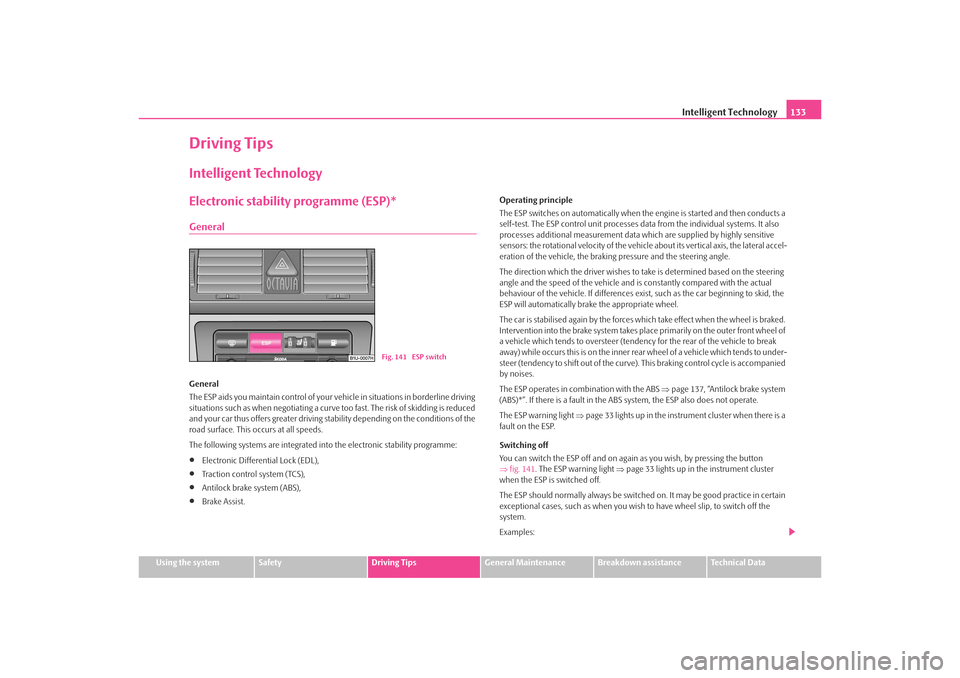
Switching off
You can switch the ESP off and on again as you wish, by pressing the button
⇒ fig. 141 . The ESP warning light ⇒page 33 lights up in the instrument cluster
when the ESP is switched off.
The ESP should normally always be switched on. It may be good practice in certain
exceptional cases, such as when you wish to have wheel slip, to switch off the
system.
Examples:
Fig. 141 ESP switch
s2ig.book Page 133 Monday, November 10, 2008 11:20 AM
Page 135 of 226
Intelligent Technology
134•
when driving with snow chains
•
when driving in deep snow or on a loose surface
•
when it is necessary to rock a ca r free when it has become stuck.
then you should switch on the ESP again.
WARNING
It is also not possible for the ESP to overcome the physical limits of the
vehicle. Even if a vehicle fitted with ESP you should still always adapt your
style of driving to the condition of the road surface and the traffic situation.
This particularly applies when driving on slippery and wet roads. The
increased safety offered must not tempt you to take greater risks than
otherwise - risk of an accident!
Note
•
All four wheels must be fitted with the same tyres in order to achieve problem-
free operation of the ESP. Differing rollin g circumferences of the tyres can lead to
an undesirable reduction in the engine output.
•
Changes to vehicle (e.g. on engine, on the brakes, on chassis or other assign-
ment of tyres and wheels) can influence the function of the ESP ⇒page 181,
“Accessories, changes and replacement of parts”.
Electronic Differential Lock (EDL)*
The electronic differential lock pr events an individual wheel from
slipping.Vehicles fitted with ABS* can be equipped with electron ic differential lock (EDL).
General
The EDL makes it much easier, and sometimes at all possible, to start off, accelerate
and climb a steep hill when the conditio ns of the road surface are unfavourable. Operating principle
The EDL is activated automatically, that is
without any action on the part of the
driver. It monitors the speeds of the driven wheels with the aid of the ABS sensors.
Should only one drive wheel begin spinning on a slippery surface there will be an
appreciable difference in the speed of the driven wheels. The EDL function brakes
the slipping wheel and the differential transmits a greater driving force to the other
driven wheel. This control proces s is also accompanied by noises.
Overheating of the brakes
The EDL switches off automatically if unusually severe stresses exist in order to
avoid excessive heat generation in the disc brake on the wheel which is being
braked. The vehicle can continue to be dr iven and has the same characteristics as
a vehicle not fitted with EDL.
The EDL switches on again automatically as soon as the brake has cooled down.
WARNING
•
Depress the accelerator carefully when accelerating on uniformly slip-
pery road surfaces, such as ice and sn ow. The driven wheels might still spin
despite the EDL and affect the stability of the vehicle - risk of an accident!
•
You should always adapt your style of driving to the condition of road
surface and to the traffic situation even when your vehicle is fitted with EDL.
The increased safety offered must not tempt you to take greater risks than
otherwise - risk of an accident!Note
•
If the ABS warning light comes on, this ma y also indicate a fault in the EDL.
Please have the car inspected as soon as possible by a specialist garage.
•
Changes to vehicle (e.g. on engine, on the brakes, on chassis or other assign-
ment of tyres and wheels) can in fluence the function of the EDL ⇒page 181,
“Accessories, changes and replacement of parts”.
s2ig.book Page 134 Monday, November 10, 2008 11:20 AM
Page 136 of 226
Intelligent Technology135
Using the system
Safety
Driving Tips
General Maintenance
Breakdown assistance
Technical Data
Traction control system (TCS)
The traction control system prevents the driven wheels from spinning
when accelerating.General
The TCS makes it much easier, and sometimes at all possible, to start off, accelerate
and climb a steep hill when the conditio ns of the road surface are unfavourable.
Operating principle
The TCS switches on automatically when th e engine is started and then conducts a
self-test. The system monitors the speeds of the driven wheels with the aid of the
ABS sensors. If the wheels are spinning, the force transmitted to the road surface is
automatically adapted by redu cing the engine speed. This occurs at all speeds.
The TCS operates in combination with the ABS ⇒page 137, “Antilock brake system
(ABS)*”. The TCS will not function if a fault exists in the ABS system.
The TCS warning light ⇒page 33 lights up in the instrument cluster when there is a
fault on the TCS.
Switching off
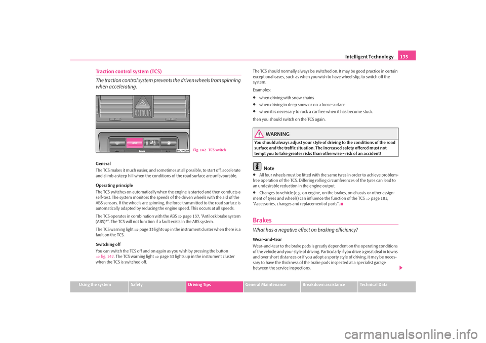
You can switch the TCS off and on again as you wish by pressing the button
⇒ fig. 142 . The TCS warning light ⇒page 33 lights up in the instrument cluster
when the TCS is switched off. The TCS should normally always be switched on. It may be good practice in certain
exceptional cases, such as when you wish
to have wheel slip, to switch off the
system.
Examples:
•
when driving with snow chains
•
when driving in deep snow or on a loose surface
•
when it is necessary to rock a car free when it has become stuck.
then you should switch on the TCS again.
WARNING
You should always adjust your style of driving to the conditions of the road
surface and the traffic situation. The increased safety offered must not
tempt you to take greater risks than otherwise - risk of an accident!
Note
•
All four wheels must be fitted with the same tyres in order to achieve problem-
free operation of the TCS. Differing rolling circumferences of the tyres can lead to
an undesirable reduction in the engine output.
•
Changes to vehicle (e.g. on engine, on the brakes, on chassis or other assign-
ment of tyres and wheels) can in fluence the function of the TCS ⇒ page 181,
“Accessories, changes and replacement of parts”.
BrakesWhat has a negative effect on braking efficiency?Wear-and-tear
Wear-and-tear to the brake pads is greatly dependent on the operating conditions
of the vehicle and your style of driving. Particularly if you drive a great deal in towns
and over short distances or if you adopt a sporty style of driving, it may be neces-
sary to have the thickness of the brake pads inspected at a specialist garage
between the service inspections.
Fig. 142 TCS switch
s2ig.book Page 135 Monday, November 10, 2008 11:20 AM