cooling SKODA OCTAVIA TOUR 2009 1.G / (1U) Owner's Manual
[x] Cancel search | Manufacturer: SKODA, Model Year: 2009, Model line: OCTAVIA TOUR, Model: SKODA OCTAVIA TOUR 2009 1.G / (1U)Pages: 226, PDF Size: 13.11 MB
Page 5 of 226
Contents
4Driving Tips
. . . . . . . . . . . . . . . . . . . . . . . . . . . . . .
Intelligent Technology
. . . . . . . . . . . . . . . . . . . . . . . .
Electronic stability programme (ESP)* . . . . . . . . . .
Brakes . . . . . . . . . . . . . . . . . . . . . . . . . . . . . . . . . . . . . . .
Brake booster . . . . . . . . . . . . . . . . . . . . . . . . . . . . . . . .
Antilock brake system (ABS)* . . . . . . . . . . . . . . . . . .
Brake Assist* . . . . . . . . . . . . . . . . . . . . . . . . . . . . . . . . .
Driving and the Environment
. . . . . . . . . . . . . . . . .
The first 1 500 kilometres and then afterwards . .
Catalytic converter . . . . . . . . . . . . . . . . . . . . . . . . . . . .
Driving in an economical and environmentally
conscious manner . . . . . . . . . . . . . . . . . . . . . . . . . . . .
Environmental compatibility . . . . . . . . . . . . . . . . . . .
Motoring abroad . . . . . . . . . . . . . . . . . . . . . . . . . . . . .
Avoiding damage to your vehicle . . . . . . . . . . . . . .
To w i n g a t r a i l e r
. . . . . . . . . . . . . . . . . . . . . . . . . . . . . . . .
Towing a trailer . . . . . . . . . . . . . . . . . . . . . . . . . . . . . . .
Detachable towing device* . . . . . . . . . . . . . . . . . . . .
General Maintenance
. . . . . . . . . . . . . . .
Taking care of your ve hicle and cleaning the
vehicle
. . . . . . . . . . . . . . . . . . . . . . . . . . . . . . . . . . . . . . . . .
General . . . . . . . . . . . . . . . . . . . . . . . . . . . . . . . . . . . . . .
Care of the exterior of vehicle . . . . . . . . . . . . . . . . . .
Care of the interior of vehicle . . . . . . . . . . . . . . . . . .
Fuel
. . . . . . . . . . . . . . . . . . . . . . . . . . . . . . . . . . . . . . . . . . . .
Petrol . . . . . . . . . . . . . . . . . . . . . . . . . . . . . . . . . . . . . . . .
Diesel . . . . . . . . . . . . . . . . . . . . . . . . . . . . . . . . . . . . . . .
Refuelling . . . . . . . . . . . . . . . . . . . . . . . . . . . . . . . . . . . .
Emergency release of fuel filler flap . . . . . . . . . . . .
Inspecting and replenishing
. . . . . . . . . . . . . . . . . .
Engine compartment . . . . . . . . . . . . . . . . . . . . . . . . .
Engine oil . . . . . . . . . . . . . . . . . . . . . . . . . . . . . . . . . . . .
Cooling system . . . . . . . . . . . . . . . . . . . . . . . . . . . . . . .
Brake fluid . . . . . . . . . . . . . . . . . . . . . . . . . . . . . . . . . . . Battery . . . . . . . . . . . . . . . . . . . . . . . . . . . . . . . . . . . . . . .
Windshield washer system . . . . . . . . . . . . . . . . . . . .
Wheels and Tyres
. . . . . . . . . . . . . . . . . . . . . . . . . . . . . .
Wheels . . . . . . . . . . . . . . . . . . . . . . . . . . . . . . . . . . . . . .
Accessories, changes and replacement of partsAccessories and replacement parts . . . . . . . . . . . . .
Technical changes . . . . . . . . . . . . . . . . . . . . . . . . . . . .Breakdown assistance
. . . . . . . . . . . . . .
Breakdown assistance
. . . . . . . . . . . . . . . . . . . . . . . .
First-aid box*, Warning triangle* and bulb set . . .
Fire extinguisher* . . . . . . . . . . . . . . . . . . . . . . . . . . . . .
Vehicle tool kit . . . . . . . . . . . . . . . . . . . . . . . . . . . . . . . .
Spray for repairing a tyre* . . . . . . . . . . . . . . . . . . . . .
Tyre repair kit* . . . . . . . . . . . . . . . . . . . . . . . . . . . . . . . .
Spare wheel . . . . . . . . . . . . . . . . . . . . . . . . . . . . . . . . . .
Changing a wheel . . . . . . . . . . . . . . . . . . . . . . . . . . . . .
Jump-starting . . . . . . . . . . . . . . . . . . . . . . . . . . . . . . . .
Tow-starting and towing vehicle . . . . . . . . . . . . . . .
Fuses and light bulbs
. . . . . . . . . . . . . . . . . . . . . . . . . .
Electric fuses . . . . . . . . . . . . . . . . . . . . . . . . . . . . . . . . .
Bulbs . . . . . . . . . . . . . . . . . . . . . . . . . . . . . . . . . . . . . . . .
Technical Data
. . . . . . . . . . . . . . . . . . . . . . . . . .
Technical Data
. . . . . . . . . . . . . . . . . . . . . . . . . . . . . . . . .
General information . . . . . . . . . . . . . . . . . . . . . . . . . .
Used abbreviations . . . . . . . . . . . . . . . . . . . . . . . . . . .
Performances . . . . . . . . . . . . . . . . . . . . . . . . . . . . . . . .
Weight . . . . . . . . . . . . . . . . . . . . . . . . . . . . . . . . . . . . . . .
Identification details . . . . . . . . . . . . . . . . . . . . . . . . . .
Fuel consumption according to the regulations
(99/100/EU) . . . . . . . . . . . . . . . . . . . . . . . . . . . . . . . . . .
Dimensions . . . . . . . . . . . . . . . . . . . . . . . . . . . . . . . . . .
1.4 ltr./55 kW - EU4 . . . . . . . . . . . . . . . . . . . . . . . . . . .
1.6 ltr./75 kW - EU4/EU2 DDK . . . . . . . . . . . . . . . . . .
1.8 ltr./110 kW - EU4/EU3D . . . . . . . . . . . . . . . . . . . . 1.9 ltr./66 kW TDI - EU3 . . . . . . . . . . . . . . . . . . . . . . . .
1.9 ltr./74 kW TDI PD - EU4 . . . . . . . . . . . . . . . . . . . .
Vehicles of the Octavia Combi group N1 . . . . . . . .
Vehicles of the Octavia Combi group - Vehicles for
reconstruction . . . . . . . . . . . . . . . . . . . . . . . . . . . . . . . .
Index
. . . . . . . . . . . . . . . . . . . . . . . . . . . . . . . . . . . . . . . .
133
133
133
135
136
137
137
139
139
140
140
143
144
144
145
145
147
149
149
149
149
154
157
157
157
158
159
161
161
164
167
169 170
174
175
175
181
181
181
183
183
183
183
184
184
184
185
185
190
191
194
194
197
203
203
203
203
203
203
203
204
205
206
208
210212
214
216
216
217
s2ig.book Page 4 Monday, November 10, 2008 11:20 AM
Page 18 of 226
Instruments and Indicator/Warning Lights17
Using the system
Safety
Driving Tips
General Maintenance
Breakdown assistance
Technical Data
In order to avoid any damage to the engine
, please pay attention to the following
notes regarding the temperature ranges:
Cold range
If the pointer is in the left-hand area of the scale it means that the engine has not
yet reached its operating temperature. Avoid running at high engine speeds, at full
throttle and at severe engine loads.
The operating range
The engine has reached its operating temp erature as soon as the pointer moves
into the mid-range of the scale. The pointe r may also move further to the right at
high engine loads and high outside temperat ures. This is not critical provided the
warning symbol
in the instrument cluster does not flash.
If the symbol
in the instrument cluster flashes it means that either the coolant
temperature is too high or the coolant level is too low. Observe the guidelines
⇒ page 30, “Coolant temperature/ Coolant quantity ”.
WARNING
Pay attention to the warning notes ⇒page 162, “Working in the engine
compartment” before opening the bonnet and inspecting the coolant level.
Caution
Additional headlights and other attached co mponents in front of the fresh air inlet
impair the cooling efficiency of the coolant. There is then a risk of the engine over-
heating at high outside temperatures and high engine loads!Fuel gaugeThe fuel gauge ⇒page 16, fig. 18 only operates when the ignition is switched
on.
The fuel tank has a capacity of about 55 litres. The warning symbol
in the instru-
ment cluster lights up when the pointer reaches the reserve marking. There are now about 7 litres of fuel remaining in the tank. This symbol is a reminder for you,
that
you must refuel .
The following will be displayed in the information display*: PLEASE REFUEL
A peep sounds as an additional warning signal.
Caution
Never run the fuel tank completely empty! An irregular fuel supply can result in
poor ignition or misfiring. Unburnt fuel may get into the exhaust system and
damage the catalytic converter.SpeedometerWarning against excessive speeds*
An acoustic warning signal will sound when the vehicle speed exceeds 120 kilome-
tres per hour. The acoustic warning signal will switch off again when the vehicle
speed goes below this speed limit.
Note
This function is only valid for some countries.
A3
s2ig.book Page 17 Monday, November 10, 2008 11:20 AM
Page 32 of 226
Instruments and Indicator/Warning Lights31
Using the system
Safety
Driving Tips
General Maintenance
Breakdown assistance
Technical Data
obtain professional assistance from a specialist garage, otherwise it could lead to
severe engine damage.
If the coolant is within the specified
range, the increased temperature may be
caused by an operating problem at the coolant fan. Check the fuse for the coolant
fan, replace it if necessary ⇒page 195, “Fuse assignment in engine compartment -
version 1” or ⇒ page 196, “Fuse assignment in en gine compartment - version 2”.
Do not continue driving if the warning light does not go off although the fluid is at
the correct level and also the fuse of the fa n is in proper order. Contact a specialist
garage to obtain assistance.
Please also refer to the additional instructions ⇒page 167, “Cooling system”.
The following text will be displayed in the information display*: STOP CHECK COOLANT SERVICE MANUAL
WARNING
•
If you must stop for technical reasons, then park the vehicle at a safe
distance from the traffic and switch off the engine and switch on the hazard
warning light system ⇒page 51.
•
Take care when opening the coolant expansion bottle. If the engine is
hot, the cooling system is pressurized - risk of scalding! It is best to allow the
engine to cool down before removing the cap.
•
Do not touch the coolant fan The coolant fan may switch on automati-
cally even if the ignition is off.
Thickness of the brake pads*
The warning light
comes on for a few seconds when the ignition is switched on.
If the warning light comes on, contact a specialist garage immediately and have
the brake pads on all of the wheels inspected.
A peep sounds as an addi tional warning signal.
The following text will be displayed in the information display*: CHECK BRAKE PADS
Windshield washer fluid level*
The warning light
comes on when the ignition is switched on if there is insuffi-
cient fluid in the windshield washer system. Top up with liquid ⇒page 174.
A peep sounds as an additional warning signal.
The following text will be displayed in the information display*: TOP UP WASH FLUID
Fuel reserve
The warning light
comes on, if the fuel level is still below 7 litres.
A peep sounds as an additional warning signal.
The following text will be displayed in the information display*: PLEASE REFUEL
Note
The Text in the information display* goes out only after refuelling and driving a
short distance.Engine oil
The warning light
lights up red (low oil pressure)
The warning light comes on for a few seconds when the ignition is switched on
3).
Stop the vehicle and switch the engine off if the warning light does not go off
within a few seconds after switching on the ignition or flashes while driving. Check
the oil level and top up with oil as necessary ⇒page 165.
3 peeps sound as an additional warning signal.
3)The warning light on vehicles fitted with information display does not come on after
switching the ignition on, but only if a fault exists or the engine oil level is too low.
s2ig.book Page 31 Monday, November 10, 2008 11:20 AM
Page 35 of 226
Instruments and Indicator/Warning Lights
34If the warning light does not go out after the engine has started, or comes on when
driving, drive to the nearest specialist garage. The vehicle battery will be discharged
in this case so switch off all non-essential electrical components.
A peep sounds as an additional warning signal.
Caution
If the warning light
comes on when driving and in addition the warning light
(cooling system fault) also comes on in display, you must then stop the car imme-
diately and switch the engine off - risk of engine damage!
Brake system
The warning light
comes on for several seconds after the ignition is switched on.
If the warning light stays on when the ignition is switched on or comes on while
driving, there is a fault in the brake system. Visit the nearest specialist garage imme-
diately and have the brake system inspected.
The following text will be displayed in the information display*:
STOP BRAKE FLUID SERVICE MANUAL
3 peeps sound as an additional warning signal.
One should get used to high pedal forces, long braking distances and long free play
of the brake pedal when driving to the next specialist garage.
For further information on the brake system ⇒page 135, “Brakes”.
Handbrake applied
The warning light
also comes on if the handbrake is applied. An audible warning
is also given if you drive the vehicle for at least 3 seconds at a speed of more than 5
km/h.
The following text will be displayed in the information display*:
HANDBRAKE ON
WARNING
•
Pay attention to the following instru ctions before checking the brake
fluid level and opening the bonnet ⇒page 162, “Working in the engine
compartment”.
•
If the brake system warning light
does not go out a few seconds after
switching on the ignition or comes on when driving, stop immediately and
check the brake fluid in the reservoir ⇒page 169, “Brake fluid”. If the fluid
level has dropped below the MIN marking, do not drive any further - risk of
accident! Obtain prof essional assistance.
Seat belt warning light*
The warning light
comes on after the ignition is switched on as a reminder to
fasten the seat belt.
In the event that the driver is not restrained, a warning signal sounds for 6 seconds.
The following text will be displayed in the information display*:
FASTEN SEATBELT
Further information on the seat belts ⇒page 110, “Seat belts”.
s2ig.book Page 34 Monday, November 10, 2008 11:20 AM
Page 86 of 226
Heating and air conditioning system85
Using the system
Safety
Driving Tips
General Maintenance
Breakdown assistance
Technical Data
Recirculated air mode
In recirculated air mode air is sucked out of the interior of the vehicle
and then fed back into the interior.Recirculated air mode prevents polluted air outside the vehicle from
getting into the vehicle, for example when driving through a tunnel or
when standing in a traffic jam.
Switching recirculated air mode on
– Press the button - the warning light lights up in the button
⇒page 83, fig. 100 .
Switching recirculated air mode off
– Press again the button - the warn ing light in the button goes out.The button cannot be pressed if the control dial is in the position
or close
to this position.
WARNING
You should not leave recirculated air mode on over a longer period of time,
as “stale” air may result in fatigue in the driver and occupants, divert your
attention and also cause the windows to mist up. The risk of having an acci-
dent increases. Switch recirculated air mode off as soon as the windows
begin misting up.Air conditioning system*Description
The air conditioning system is a combined cooling and heating
system. It makes it possible to op timally control the air temperature
at any season of the year.Description of the air conditioning system
It is important for your safety and for your driving comfort that the air conditioning
system is operating properly.
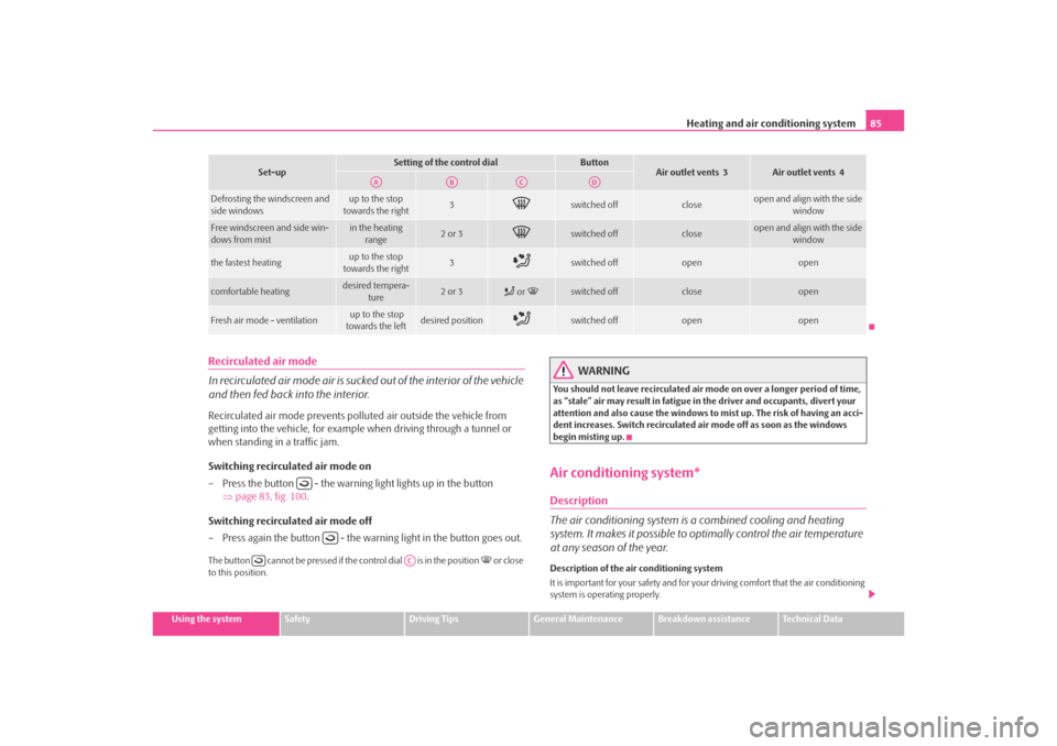
Set-up
Setting of the control dial
Button
Air outlet vents 3
Air outlet vents 4
Defrosting the windscreen and
side windows
up to the stop
towards the right
3
switched off
close
open and align with the side window
Free windscreen and side win-
dows from mist
in the heating range
2 or 3
switched off
close
open and align with the side window
the fastest heating
up to the stop
towards the right
3
switched off
open
open
comfortable heating
desired tempera-
ture
2 or 3
or
switched off
close
open
Fresh air mode - ventilation
up to the stop
towards the left
desired position
switched off
open
open
AA
AB
AC
AD
AC
s2ig.book Page 85 Monday, November 10, 2008 11:20 AM
Page 87 of 226
Heating and air conditioning system
86The air conditioning only operates if button ⇒fig. 101 is pressed and the
following conditions are met:•
engine running,
•
outside temperature above +5 °C and
•
blower switch switched on (positions 1 to 4).
If the cooling system is switched on, the temperature and air humidity drops in the
vehicle. The wellbeing of the occupants of the car is enhanced as a result of this
particularly at high outside temperatures and a high air humidity. The system
prevents the windows misting up during the cold season of the year.
The heating effect is dependent upon th e coolant temperature, thus full heat
output only occurs when the engine has reached its operating temperature.
It is possible to briefly activate recirc ulated air mode in order to enhance the
cooling effect ⇒ .
Air at a temperature of about 5°C may flow out of the vents under certain circum-
stances when the cooling system is operating. Lengthy and uneven distribution of
the air flow out of the vents (in particular at the leg area) and large differences in
temperature, for example when getting out of the vehicle, can result in chills in
sensitive persons.
The air inlet in front of the windscreen must be free of ice, snow or leaves in order
to ensure that the heating and cooling systems operate properly.
After switching on the cooling Condensation from the evaporator of the air condi-
tioning may drip down and form a puddle below the vehicle. This is quite normal
and not an indication of a leak!
WARNING
•
For your own safety and that of other road users, ensure that all the
windows are free of ice, snow and mistin g. Please familiarize yourself about
how to correctly operate th e heating and ventilation systems, how to demist
and defrost the windows, as well as with the cooling mode.
•
You should not leave recirculated air mode on over a longer period of
time, as “stale” air may result in fatigue in the driver and occupants, divert
your attention and also cause the windows to mist up. The risk of having an accident increases. Switch recirculated air mode off as soon as the windows
begin misting up.
Note
•
We recommend that you do not smoke in the vehicle when the recirculating air
mode is operating since the smoke which is drawn at the evaporator from the inte-
rior of the vehicle forms deposits in the evaporator of the air conditioning system.
This produces a permanent odour when th e air conditioning system is operating
which can only be eliminated through co nsiderable effort and expense (replace-
ment of compressor).
Using the systemSetting temperature
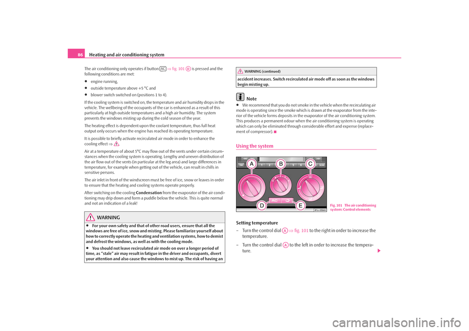
– Turn the control dial ⇒fig. 101 to the right in order to increase the
temperature.
– Turn the control dial to the left in order to increase the tempera- ture.
AC
AD
WARNING (continued)
Fig. 101 The air conditioning
system: Control elements
AAAA
s2ig.book Page 86 Monday, November 10, 2008 11:20 AM
Page 88 of 226
Heating and air conditioning system87
Using the system
Safety
Driving Tips
General Maintenance
Breakdown assistance
Technical Data
Controlling blower
– Turn the blower switch into one of the positions, 1 to 4, in order to
switch the blower on.
– Turn the blower switch into position 0 in order to switch the blower off.
– IF you wish to close the inlet for fresh air, use the switch - Recirculated air mode ⇒page 88.
Control for air distribution
– You can adjust the direction of the air flow using the air distribution
control ⇒page 83.
switching cooling on and off
– Press the button ⇒page 86, fig. 101 . The warning light lights
up in the button. – When you again press the switch , the cooling system is switched
off. The warning light in the button goes out.
Note
•
The whole heat output will be needed to unfrost the windscreen and side
windows. No warm air will be fed to the footwell. This can lead to restriction of the
heating comfort.
•
The used air streams out through the air removal openings in the luggage
compartment.
•
If the cooling system has not been switched on for a lengthy period, odours may
be produced at the evaporator because of deposits. Switch the cooling system on
at least once a month for approximately 5 mi nutes at the highest blower stage - also
during the cold season of the year - in order to remove such odours. Also open a
window for a short time.
•
Please refer to the information regarding recirculated air mode ⇒page 88.
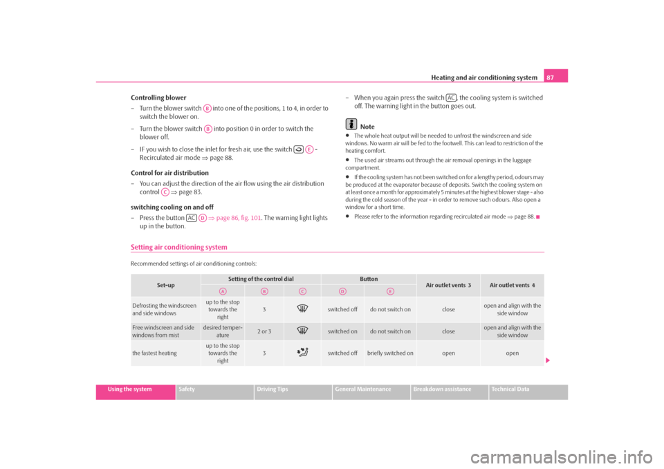
Setting air conditioning systemRecommended settings of ai r conditioning controls:
ABAB
AE
AC
AC
AD
AC
Set-up
Setting of the control dial
Button
Air outlet vents 3
Air outlet vents 4
Defrosting the windscreen
and side windows
up to the stop
towards the right
3
switched off
do not switch on
close
open and align with the side window
Free windscreen and side
windows from mist
desired temper-
ature
2 or 3
switched on
do not switch on
close
open and align with the side window
the fastest heating
up to the stop towards the
right
3
switched off
briefly switched on
open
open
AA
AB
AC
AD
AE
s2ig.book Page 87 Monday, November 10, 2008 11:20 AM
Page 89 of 226
Heating and air conditioning system
88Recirculated air mode
In recirculated air mode air is sucked out of the interior of the vehicle
and then fed back into the interior.Recirculated air mode prevents polluted air outside the vehicle from
getting into the vehicle, for example when driving through a tunnel or
when standing in a traffic jam.
Switching recirculated air mode on
– Press the button ⇒page 86, fig. 101 - the warning light lights up
in the button.
Switching recirculated air mode off
– Press again the button - the warning light in the button goes out.The button cannot be pressed if the control dial is in the position
or close
to this position.
WARNING
You should not leave recirculated air mode on over a longer period of time,
as “stale” air may result in fatigue in the driver and occupants, divert your
attention and also cause the windows to mist up. The risk of having an acci-
dent increases. Switch recirculated air mode off as soon as the windows
begin misting up.Using the air conditioning system economicallyThe compressor on the air co nditioning system uses power from the engine when
in cooling mode which will effect the fuel consumption.
It recommended to open the windows or the doors of a vehicle for which the inte-
rior has been strongly heated through the effect of direct sunlight in order to allow
the heated air to escape.
The cooling system should not be switched on while travelling when the window is
open.
The desired interior temperature can also be achieved without switching in the
cooling system just by switching to fresh air mode.
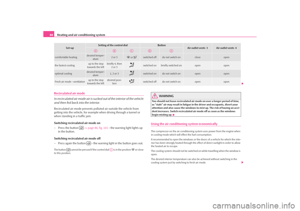
comfortable heating
desired temper- ature
2 or 3
or
switched off
do not switch on
close
open
the fastest cooling
up to the stop
towards the left
briefly 4, then 2or 3
switched on
briefly switched on
open
open
optimal cooling
desired temper- ature
1, 2 or 3
switched on
do not switch on
open
open
Fresh air mode - ventilation
up to the stop
towards the left
desired posi- tion
switched off
do not switch on
open
open
Set-up
Setting of the control dial
Button
Air outlet vents 3
Air outlet vents 4
AA
AB
AC
AD
AE
AC
s2ig.book Page 88 Monday, November 10, 2008 11:20 AM
Page 90 of 226
Heating and air conditioning system89
Using the system
Safety
Driving Tips
General Maintenance
Breakdown assistance
Technical Data
For the sake of the environment
When you economize on fuel, you also reduce pollutant emissions.Climatronic* (automatic air conditioning)Description
The Climatronic system is a combination of an automatic heating,
fresh air and cooling system which provides optimal comfort for the
occupants of the car.The Climatronic maintains a constant temp erature fully automatically, once it has
been set. This is achiev ed by automatically varying the temperature of the
outflowing air, the blower stages and the ai r distribution. The system also takes into
account bright sunlight which eliminates the need to alter the settings manually.
The automatic mode ⇒ page 91 ensures maximum wellbeing of the occupants at
all times of the year.
Description of Climatronic system
The cooling operates only if the following conditions are met:•
engine running,
•
outside temperature above +5 °C,
•
the button is not pressed.
If the cooling system is switched on, the temperature and air humidity drops in the
vehicle. The wellbeing of the occupants of the car is enhanced as a result of this
particularly at high outs ide temperatures and a high air humidity. The system
prevents the windows misting up during the cold season of the year.
The heating effect is dependent upon th e coolant temperature, thus full heat
output only occurs when the engine has reached its operating temperature.
It is possible to briefly activate recirc ulated air mode in order to enhance the
cooling effect ⇒ .
The air inlet in front of the windscreen must be free of ice, snow or leaves in order
to ensure that the heating and cooling systems operate properly. The AC compressor is switched off at
a high coolant temperature in order to
provide cooling at a high load of the engine.
After switching on the cooling Condensation from the evaporator of the air condi-
tioning may drip down and form a puddle below the vehicle. This is quite normal
and not an indication of a leak!
If you make a change before switching off the ignition, which differs from the auto-
matic mode, the changed functions remain stored. Only the function “circulating
air” is erased 20 minutes after switching off the ignition.
Recommended setting for all periods of the year:
•
Set the temperature to 22 °C (72 °F).
•
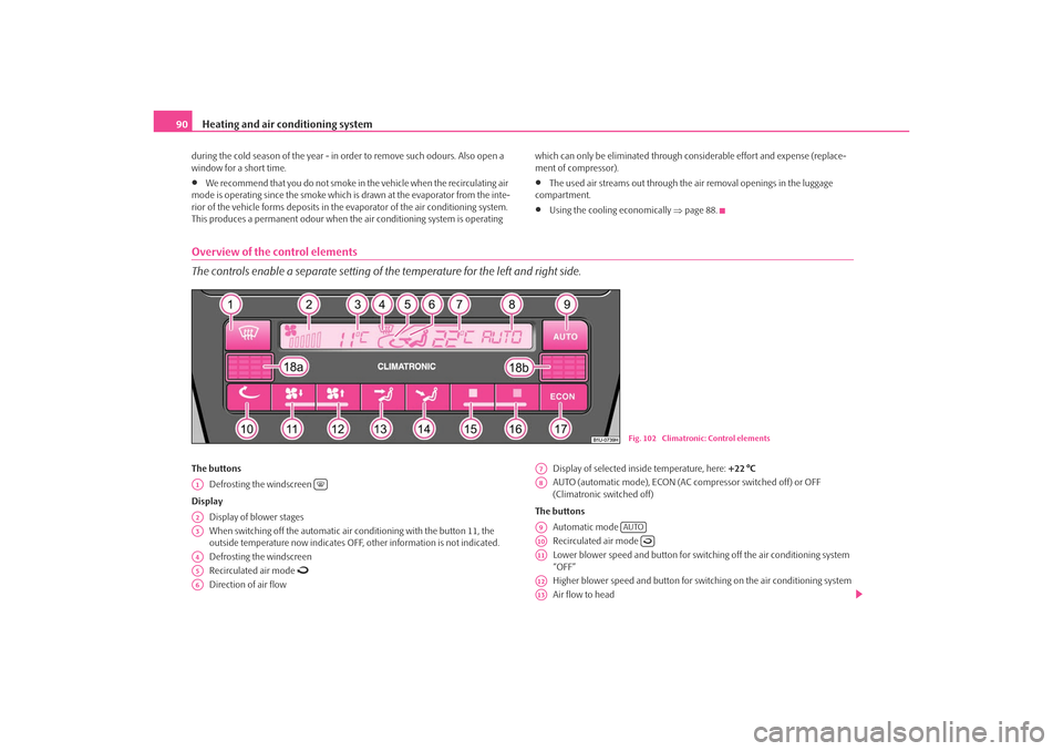
Press the button ⇒page 90, fig. 102 .
•
Move the air outlet vents 3 and 4 so that the air flow is directed slightly upwards
⇒ page 83, fig. 99 .
Switching over between degrees Celsius and degrees Fahrenheit
Press and hold the buttons 17 and 9 ⇒page 90, fig. 102. The infor-
mation in the desired temperature measuring unit appears in the display.
WARNING
•
For your own safety and that of other road users, ensure that all the
windows are free of ice, snow and mistin g. Please familiarize yourself about
how to correctly operate th e heating and ventilation systems, how to demist
and defrost the windows, as well as with the cooling mode.
•
You should not leave recirculated air mode on over a longer period of
time, as “stale” air may result in fatigue in the driver and occupants, divert
your attention and also cause the windows to mist up. The risk of having an
accident increases. Switch recirculated air mode off as soon as the windows
begin misting up.Note
•
If the cooling system has not been switched on for a lengthy period, odours may
be produced at the evaporator because of deposits. Switch the cooling system on
at least once a month for approximately 5 mi nutes at the highest blower stage - also
ECON
AUTO
ECON
AUTO
s2ig.book Page 89 Monday, November 10, 2008 11:20 AM
Page 91 of 226
Heating and air conditioning system
90during the cold season of the year - in order to remove such odours. Also open a
window for a short time.•
We recommend that you do not smoke in the vehicle when the recirculating air
mode is operating since the smoke which is drawn at the evaporator from the inte-
rior of the vehicle forms deposits in the evaporator of the air conditioning system.
This produces a permanent odour when the air conditioning system is operating which can only be eliminated through co
nsiderable effort and expense (replace-
ment of compressor).
•
The used air streams out through the air removal openings in the luggage
compartment.
•
Using the cooling economically ⇒page 88.
Overview of the control elements
The controls enable a separate setting of the temperature for the left and right side.The buttons
Defrosting the windscreen
Display Display of blower stages
When switching off the automatic air co nditioning with the button 11, the
outside temperature now indicates OFF, other information is not indicated.
Defrosting the windscreen
Recirculated air mode
Direction of air flow Display of selected inside temperature, here:
+22 °C
AUTO (automatic mode), ECON (AC compressor switched off) or OFF
(Climatronic switched off)
The buttons Automatic mode
Recirculated air mode
Lower blower speed and button for switch ing off the air conditioning system
“OFF”
Higher blower speed and button for switching on the air conditioning system
Air flow to head
Fig. 102 Climatronic: Control elements
A1
A2A3A4A5A6
A7A8A9
AUTO
A10
A11A12A13
s2ig.book Page 90 Monday, November 10, 2008 11:20 AM