buttons SKODA OCTAVIA TOUR 2009 1.G / (1U) Owner's Manual
[x] Cancel search | Manufacturer: SKODA, Model Year: 2009, Model line: OCTAVIA TOUR, Model: SKODA OCTAVIA TOUR 2009 1.G / (1U)Pages: 226, PDF Size: 13.11 MB
Page 10 of 226
Cockpit9
Using the system
Safety
Driving Tips
General Maintenance
Breakdown assistance
Technical Data
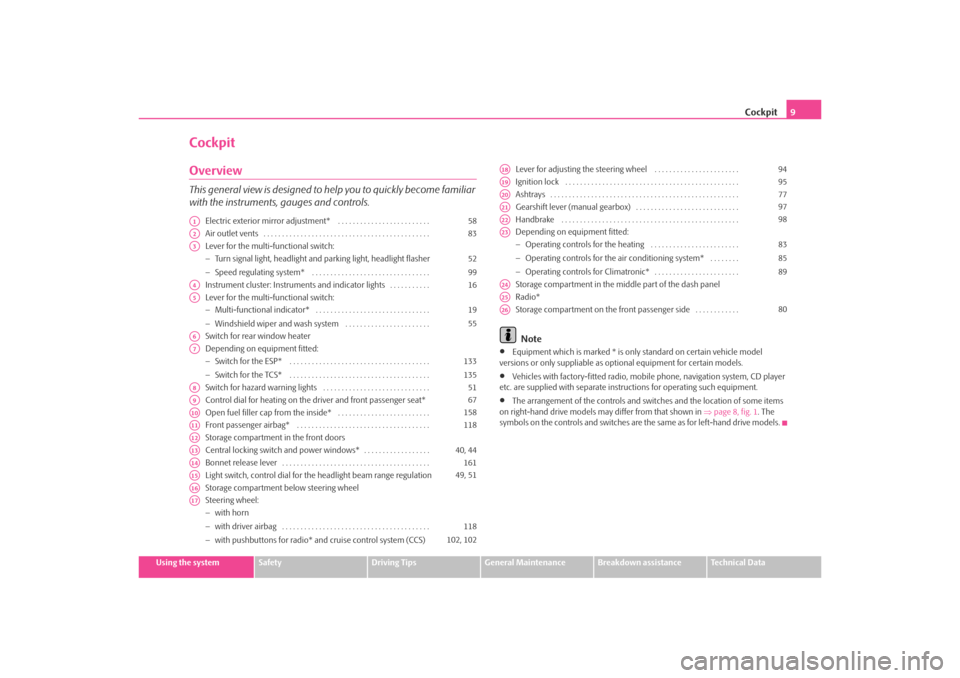
CockpitOverviewThis general view is designed to help you to quickly become familiar
with the instruments, gauges and controls.
Electric exterior mirror adjustment* . . . . . . . . . . . . . . . . . . . . . . . . .
Air outlet vents . . . . . . . . . . . . . . . . . . . . . . . . . . . . . . . . . . . . . . . . . . . . .
Lever for the multi-functional switch:
−Turn signal light, headlight and parking light, headlight flasher
− Speed regulating system* . . . . . . . . . . . . . . . . . . . . . . . . . . . . . . . .
Instrument cluster: Instrum ents and indicator lights . . . . . . . . . . .
Lever for the multi-functional switch:
− Multi-functional indicator* . . . . . . . . . . . . . . . . . . . . . . . . . . . . . . .
− Windshield wiper and wash system . . . . . . . . . . . . . . . . . . . . . . .
Switch for rear window heater
Depending on equipment fitted:
− Switch for the ESP* . . . . . . . . . . . . . . . . . . . . . . . . . . . . . . . . . . . . . .
− Switch for the TCS* . . . . . . . . . . . . . . . . . . . . . . . . . . . . . . . . . . . . . .
Switch for hazard warning lights . . . . . . . . . . . . . . . . . . . . . . . . . . . . .
Control dial for heating on the driver and front passenger seat*
Open fuel filler cap from the inside* . . . . . . . . . . . . . . . . . . . . . . . . .
Front passenger airbag* . . . . . . . . . . . . . . . . . . . . . . . . . . . . . . . . . . . .
Storage compartment in the front doors
Central locking switch and power windows* . . . . . . . . . . . . . . . . . .
Bonnet release lever . . . . . . . . . . . . . . . . . . . . . . . . . . . . . . . . . . . . . . . .
Light switch, control dial for the headlight beam range regulation
Storage compartment below steering wheel
Steering wheel:
− with horn
− with driver airbag . . . . . . . . . . . . . . . . . . . . . . . . . . . . . . . . . . . . . . . .
− with pushbuttons for radio* an d cruise control system (CCS) Lever for adjusting the steering wheel . . . . . . . . . . . . . . . . . . . . . . .
Ignition lock . . . . . . . . . . . . . . . . . . . . . . . . . . . . . . . . . . . . . . . . . . . . . . .
Ashtrays . . . . . . . . . . . . . . . . . . . . . . . . . . . . . . . . . . . . . . . . . . . . . . . . . . .
Gearshift lever (manual gearbox) . . . . . . . . . . . . . . . . . . . . . . . . . . . .
Handbrake . . . . . . . . . . . . . . . . . . . . . . . . . . . . . . . . . . . . . . . . . . . . . . . .
Depending on equipment fitted:
−
Operating controls for the heating . . . . . . . . . . . . . . . . . . . . . . . .
− Operating controls for the air conditioning system* . . . . . . . .
− Operating controls for Climatronic* . . . . . . . . . . . . . . . . . . . . . . .
Storage compartment in the middle part of the dash panel
Radio*
Storage compartment on the front passenger side . . . . . . . . . . . .
Note
•
Equipment which is marked * is only standard on certain vehicle model
versions or only suppliable as op tional equipment for certain models.
•
Vehicles with factory-fitted radio, mobile phone, navigation system, CD player
etc. are supplied with separate instru ctions for operating such equipment.
•
The arrangement of the controls and swit ches and the location of some items
on right-hand drive models may differ from that shown in ⇒page 8, fig. 1 . The
symbols on the controls and switches are the same as for left-hand drive models.
A1
58
A2
83
A3
52
99
A4
16
A5
19
55
A6A7
133
135
A8
51
A9
67
A10
158
A11
118
A12A13
40, 44
A14
161
A15
49, 51
A16A17
118
102, 102
A18
94
A19
95
A20
77
A21
97
A22
98
A23
83
85
89
A24A25A26
80
s2ig.book Page 9 Monday, November 10, 2008 11:20 AM
Page 14 of 226
The brief instruction13
Using the system
Safety
Driving Tips
General Maintenance
Breakdown assistance
Technical Data
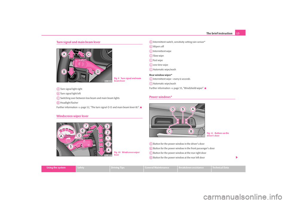
Turn signal and main beam lever Turn signal light right
Turn signal light left
Switching over between low beam and main beam lights
Headlight flasher
Further information ⇒page 52, “The turn signal and main beam lever ”.Windscreen wiper lever
Intermittent switch, sensitivity setting rain sensor*
Wipers off
Intermittent wipe
Slow wipe
Fast wipe
one time wipe
Automatic wipe/wash
Rear window wiper* Intermittent wipe - every 6 seconds
Automatic wipe/wash
Further information ⇒page 55, “Windshield wiper”.Power windows* Button for the power window in the driver's door
Button for the power window in the front passenger's door
Button for the power window at the rear right door
Button for the power window at the rear left door
Fig. 9 Turn signal and main
beam lever
AAABACAD
Fig. 10 Windscreen wiper
lever
AAA0A1A2A3A4A5A6A7
Fig. 11 Buttons on the
driver's door
AAABACAD
s2ig.book Page 13 Monday, November 10, 2008 11:20 AM
Page 15 of 226
The brief instruction
14 Safety switch
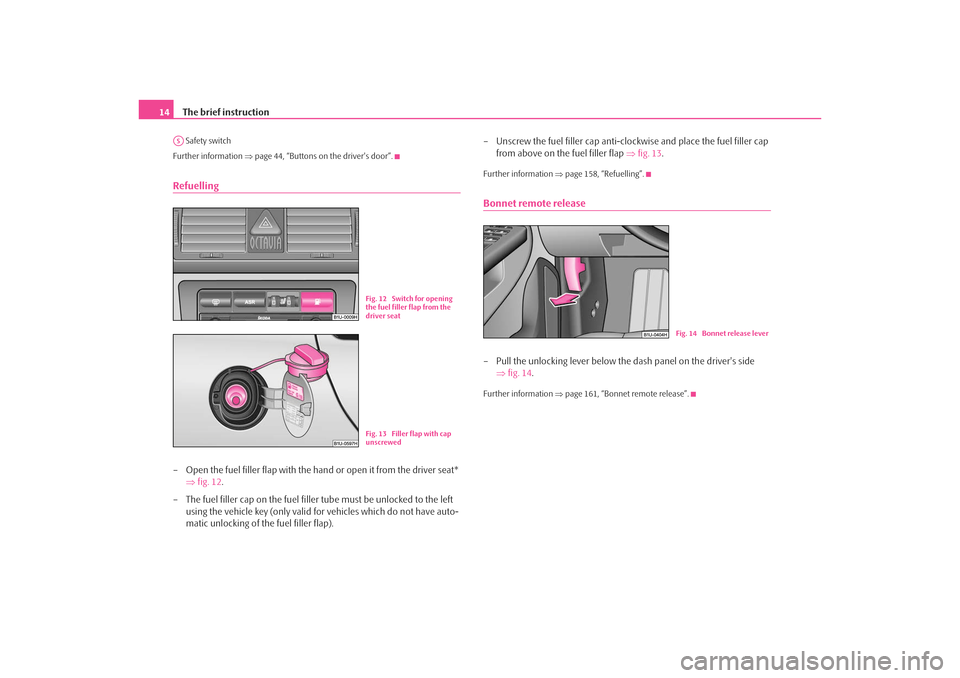
Further information ⇒page 44, “Buttons on the driver's door”.Refuelling– Open the fuel filler flap with the hand or open it from the driver seat*
⇒fig. 12 .
– The fuel filler cap on the fuel fille r tube must be unlocked to the left
using the vehicle key (only valid for vehicles which do not have auto-
matic unlocking of the fuel filler flap). – Unscrew the fuel filler cap anti-clo
ckwise and place the fuel filler cap
from above on the fuel filler flap ⇒fig. 13 .
Further information ⇒page 158, “Refuelling”.Bonnet remote release– Pull the unlocking lever below the dash panel on the driver's side
⇒fig. 14 .Further information ⇒page 161, “Bonnet remote release”.
AS
Fig. 12 Switch for opening
the fuel filler flap from the
driver seatFig. 13 Filler flap with cap
unscrewed
Fig. 14 Bonnet release lever
s2ig.book Page 14 Monday, November 10, 2008 11:20 AM
Page 41 of 226
Unlocking and locking
40
NoteThe opened driver door cannot be locked. It must be locked separately after closing
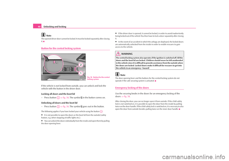
it.Button for the central locking systemIf the vehicle is not locked from outside, you can unlock and lock the
vehicle with the button in the driver door.
Locking all doors and the boot lid
– Press button ⇒ fig. 38. The symbol
in the button comes on.
Unlocking all doors and the boot lid
– Press button ⇒ fig. 38. The symbol goes out in the button.
The following applies if you have lo cked your vehicle using the button :•
It is not possible to open the doors or the boot lid from the outside (safety
feature, e.g. when stopping at traffic lights etc.).
•
You can unlock the doors individually from the inside and open them by pulling
the door opening lever.
•
If the driver door is opened, it cannot be locked, in order to avoid inadvertently
being locked out of the vehicle You then have to lock a door separately after closing
it.
•
In the event of an accident in which the airbags are deployed, the locked doors
are automatically unlocked from the inside in order to enable rescuers to gain
access to the vehicle.
WARNING
The central locking system al so operates if the ignition is switched off. All the
doors and the boot lid are locked. Children should never be left unattended
in the vehicle since it is difficult to provide assistance from the outside when
the doors are locked. Locked doors make it difficult for rescuers to get into
the vehicle in an emergency - hazard!
Note
The door opening lever and the buttons for the central locking system do not
operate if the safe securing system is activated.Emergency locking of the doorsUse the securing knobs in the doors for an emergency locking of the
doors ⇒fig. 38 .After closing the door, you can no longer open it from outside. If the child safety
lock is not switched on, it is possible to open the door from the inside by pulling
twice on the door handle. If the child safety lock is switched on, it is necesary to also
open the door from outside besides pu lling twice on the inner door handle.
Fig. 38 Button for the central
locking system
A1A2
A1
s2ig.book Page 40 Monday, November 10, 2008 11:20 AM
Page 43 of 226

Unlocking and locking
42Unlocking and locking carUnlocking the vehicle
– Press button for about 1 second.
Locking the vehicle
– Press button for about 1 second.
Deactivating safe securing system
– Press button twice in 2 seconds. Further information ⇒page 38.
Folding out of the key
– Press button .
Folding up of the key
– Press button and collapse the key bit in the housing.The turn signal lights flash twice as confirmation that the vehicle has been
unlocked. The vehicle will lock again auto matically if you unlock the vehicle using
button but do not open a door or the boot lid within the next 30 seconds. This
function is intended to prevent the car being unlocked unintentionally. The safe securing system along with the anti-theft alarm system are, however,
deactivated during these 30 seconds.
In addition, when the car is
unlocked, the power seats and exterior mirrors* move
into the position assigned to this key. The stored setting of driver seat and exterior
mirrors is retrieved.
The turn signal lights flash once to co nfirm that the vehicle has been correctly
locked. If the turn signal lights do not fl ash, check the doors, bonnet and boot lid
again to ensure that they are closed. If th e doors, the bonnet or the boot lid remain
open when the anti-theft alarm system is activated, the turn signal lights do not
flash until after they have been closed.
When the vehicle is unlocked or locked, the interior lights in the door contact are
automatically switched on or off.
WARNING
If the vehicle is locked from the outsid e and the safe securing system is acti-
vated, there must not be any person in the vehicle as it is then not possible
to open either a door or a window from the inside. The locked doors make it
more difficult for rescuers to get into the vehicle in an emergency - hazard!
Note
•
Operate the radio remote control only when the doors and boot lid are closed
and you have visual co ntact with the vehicle.
•
Once in the car, you must not press the lock button
of the radio remote
control before inserting the key into the ignition lock in order to avoid the car being
inadvertently locked and, in addition, the anti-theft alarm system* being switched
on. Should this happen, press the unlock button
of the radio remote control.
Synchonisation of the remote controlIf the vehicle cannot be unlocked by actuatin g the remote control system then it is
possible that the code in the key and the control unit in the vehicle are no longer
synchronised. This can occur when the buttons on the radio-operated key are actu-
Fig. 40 Folding key with
radio remote control
A1A2A2A3A3
A1
s2ig.book Page 42 Monday, November 10, 2008 11:20 AM
Page 45 of 226
Unlocking and locking
44Power windows*Buttons on the driver's doorThe power windows operate only when ignition is switched on. After
switching the ignition off, the power windows can still be operated for
approx. 10 minutes if a front door is opened.
Opening a window
– A window is opened by pressing lightly on the respective button in the
door. The process stops when one releases the button.
– Additionally you can open the window automatically (fully opened) by pressing the button up to the stop. Renewed pressing of the button
causes the window to stop immediately.
Closing a window
– A window is closed through pulling lightly on the respective button in
the door. The closing process stops when one releases the button.
– Additionally you can close the window automatically (fully closed) by pulling the button up to the stop. Renewed pulling of the button
causes the window to stop immediately.
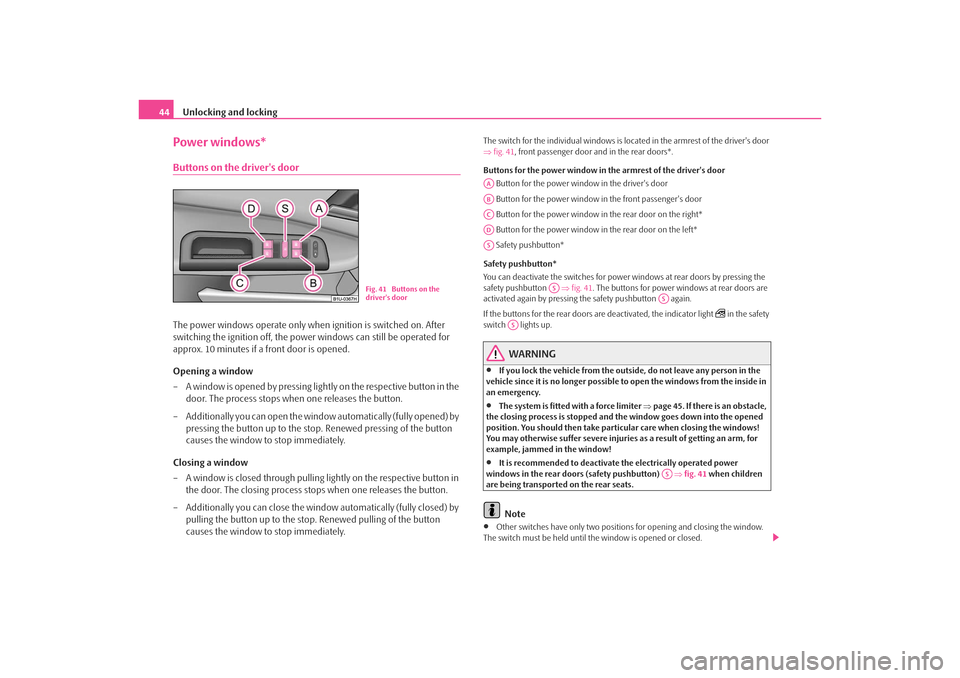
The switch for the individual windows is located in the armrest of the driver's door
⇒fig. 41 , front passenger door and in the rear doors*.
Buttons for the power window in the armrest of th e driver's door
Button for the power window in the driver's door
Button for the power window in the front passenger's door
Button for the power window in the rear door on the right*
Button for the power window in the rear door on the left*
Safety pushbutton*
Safety pushbutton*
You can deactivate the switches for power windows at rear doors by pressing the
safety pushbutton ⇒fig. 41 . The buttons for power windows at rear doors are
activated again by pressing the safety pushbutton again.
If the buttons for the rear doors are deactivated, the indicator light
in the safety
switch lights up.
WARNING
•
If you lock the vehicle from the outside, do not leave any person in the
vehicle since it is no longer possible to open the windows from the inside in
an emergency.
•
The system is fitted with a force limiter ⇒page 45. If there is an obstacle,
the closing process is stopped and the window goes down into the opened
position. You should then take particular care when closing the windows!
You may otherwise suffer severe injuries as a result of getting an arm, for
example, jammed in the window!
•
It is recommended to deactivate the electrically operated power
windows in the rear doors (safety pushbutton) ⇒fig. 41 when children
are being transported on the rear seats.Note
•
Other switches have only two positions for opening and closing the window.
The switch must be held until th e window is opened or closed.
Fig. 41 Buttons on the
driver's door
AAABACADAS
AS
AS
AS
AS
s2ig.book Page 44 Monday, November 10, 2008 11:20 AM
Page 63 of 226
Seats and Storage
62•
In view of the fact that the seats can also be adjusted when the ignition is
switched off (even when ignition key withdrawn), you should never leave
children unattended in the car.
•
The backrests must not be angled too far back when driving otherwise
this will affect proper operation of th e seat belts and of the airbag system -
risk of injury!Note
If the movement of the seat is inadverten tly interrupted during an adjustment, once
again press the switch in the appropriate direction and continue with the adjust-
ment of the seat to the end.Storing settingStoring seat and exterior mirror settings for driving forward
– Switch on the ignition.
– Adjust the seat ⇒page 61.
– Adjust both exterior mirrors ⇒page 58. – Press one of the memory buttons and hold the button pressed for
about 3 seconds until an audible sign al confirms that the setting has
been stored. The setting of this button was stored.
Storing exterior mirror setting for reversing*
– Switch on the ignition.
– Turn the exterior mirror control to position
⇒ page 58.
– Engage reverse gear.
– Move the right exterior mirror into the desired position ⇒page 58.
– Press one of the memory buttons and hold the button pressed for about 3 seconds until an audible sign al confirms that the setting has
been stored. The setting of the selected button was stored.
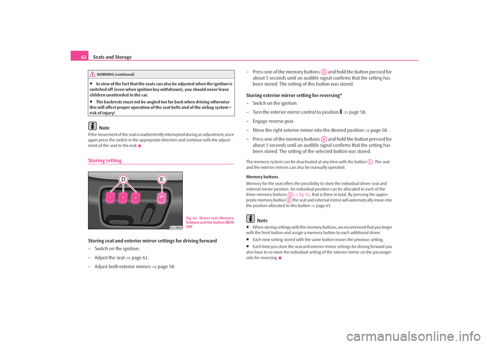
The memory system can be deactivated at any time with the button . The seat
and the exterior mirrors can also be manually operated.
Memory buttons
Memory for the seat offers the possibility to store the individual driver seat and
external mirror position. An individual po sition can be allocated to each of the
three memory buttons ⇒fig. 61 , that is three in total. By pressing the appro-
priate memory button the seat and extern al mirror will automatically move into
the position allocated to this button ⇒page 63.
Note
•
When storing settings with the memory buttons, we recommend that you begin
with the front button and assign a memory button to each additional driver.
•
Each new setting stored with the same button erases the previous setting.
•
Each time you store the seat and exterior mirror settings for driving forward you
also have to re-store the individual settin g of the exterior mirror on the passenger
side for reversing.
WARNING (continued)
Fig. 61 Driver seat: Memory
buttons and the button MEM
OFF
ADAD
AE
ADAD
s2ig.book Page 62 Monday, November 10, 2008 11:20 AM
Page 64 of 226
Seats and Storage63
Using the system
Safety
Driving Tips
General Maintenance
Breakdown assistance
Technical Data
Assigning radio remote control* to the memory buttonsAfter storing the settings of the seat and exterior mirrors, you have 10
seconds in order to assign the radio remote control to the appropriate
memory button.
– Withdraw the ignition key.
– Press the release button ⇒page 42 and hold it pressed for 1 second
until an audible signal confirms that the setting has been stored. The
setting is stored with the memory button which you have selected.If you wish to be able to retrieve the settings which are stored in the memory by also
using the radio remote control, you have to assign the radio remote control to a
memory button in each case.
If you wish, you can obtain an additional key with radio remote control from a
specialist garage and then assign the radio remote control to another memory
button.
Note
•
If the radio remote control had previous ly been assigned to another memory
button, this setting is then erased by the new assignment.
•
If you assign the radio remote control to a memory button which has already
been assigned to a radio remote control, the old assignment is also replaced by a
new assignment in this case.
•
The assignment of the radio remote control to a memory button is retained,
however, after reassigning the seats and exterior mirrors.
Retrieving seat and exterior mirror settings for driving forward
You can retrieve the stored settings either with the memory buttons or also with the radio remote control*.Retrieving the settings of the seat and mirrors can only be carried out
when the ignition is switched off for safety reasons. Retrieving the
settings can be carried out in two different ways:
Retrieving settings with memory buttons
– By pressing briefly: with the door open, operate the desired memory
button ⇒page 62, fig. 61 with one-touch. The seat and the exte-
rior mirrors now move automatically into the stored position.
– By pressing for a long period of time: with the driver door open or
closed, press and hold the desired memory button until the seat
and the exterior mirrors have moved into the stored position.
Retrieving settings with remote control*
– If the driver door is closed and the ignition is switched off, briefly press the unlock button of the radio remote control ⇒page 42 and then
open the driver door.
– The seat and exterior mirrors now move automatically into the stored
positions.
Retrieving setting of exterior mirror for reversing*
– Turn the rotary knob for the exterior mirror setting into the position
⇒ page 58 before engaging the reverse gear.
Emergency Off
– Press any button on the driver seat.
AD
AD
AD
s2ig.book Page 63 Monday, November 10, 2008 11:20 AM
Page 65 of 226
Seats and Storage
64
NoteIf the memory button is pressed once agai n during the automatic setting of the seat
and the exterior mirrors, the setting operation is interrupted. After repeated
pressing of the same button, the setting operation is continued to the end. If one of
the two remaining memory buttons is pressed, the stored setting of this button is
retrieved.Information concerning the off switch of the memory systemAfter pressing the off switch of the memory system ⇒page 62, fig. 61 , the
memory system is deactiva ted. You can only adjust the seat and the exterior
mirrors manually. You can switch on th e memory system again by once again
pressing the off switch of the memory system. The setting is not carried out to
the end if a retrieved setting operation is interrupted.
We recommend that you switch off the memory system with the off switch if the
vehicle is used for a short period by a driver and you do not wish to store any partic-
ular settings of the seat and mirrors in this case.Head restraints
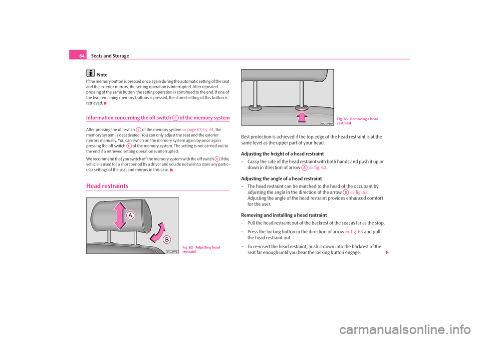
Best protection is achieved if the top edge of the head restraint is at the
same level as the upper part of your head.
Adjusting the height of a head restraint
– Grasp the side of the head restraint with both hands and push it up or down in direction of arrow ⇒fig. 62 .
Adjusting the angle of a head restraint
– The head restraint can be matched to the head of the occupant by
adjusting the angle in the direction of the arrow ⇒fig. 62 .
Adjusting the angle of the head re straint provides enhanced comfort
for the user.
Removing and installing a head restraint
– Pull the head restraint out of the backrest of the seat as far as the stop.
– Press the locking button in the direction of arrow ⇒fig. 63 and pull
the head restraint out.
– To re-insert the head restraint, push it down into the backrest of the seat far enough until you hear the locking button engage.
AE
AE
AE
AE
Fig. 62 Adjusting head
restraint
Fig. 63 Removing a head
restraint
AA
AB
s2ig.book Page 64 Monday, November 10, 2008 11:20 AM
Page 90 of 226
Heating and air conditioning system89
Using the system
Safety
Driving Tips
General Maintenance
Breakdown assistance
Technical Data
For the sake of the environment
When you economize on fuel, you also reduce pollutant emissions.Climatronic* (automatic air conditioning)Description
The Climatronic system is a combination of an automatic heating,
fresh air and cooling system which provides optimal comfort for the
occupants of the car.The Climatronic maintains a constant temp erature fully automatically, once it has
been set. This is achiev ed by automatically varying the temperature of the
outflowing air, the blower stages and the ai r distribution. The system also takes into
account bright sunlight which eliminates the need to alter the settings manually.
The automatic mode ⇒ page 91 ensures maximum wellbeing of the occupants at
all times of the year.
Description of Climatronic system
The cooling operates only if the following conditions are met:•
engine running,
•
outside temperature above +5 °C,
•
the button is not pressed.
If the cooling system is switched on, the temperature and air humidity drops in the
vehicle. The wellbeing of the occupants of the car is enhanced as a result of this
particularly at high outs ide temperatures and a high air humidity. The system
prevents the windows misting up during the cold season of the year.
The heating effect is dependent upon th e coolant temperature, thus full heat
output only occurs when the engine has reached its operating temperature.
It is possible to briefly activate recirc ulated air mode in order to enhance the
cooling effect ⇒ .
The air inlet in front of the windscreen must be free of ice, snow or leaves in order
to ensure that the heating and cooling systems operate properly. The AC compressor is switched off at
a high coolant temperature in order to
provide cooling at a high load of the engine.
After switching on the cooling Condensation from the evaporator of the air condi-
tioning may drip down and form a puddle below the vehicle. This is quite normal
and not an indication of a leak!
If you make a change before switching off the ignition, which differs from the auto-
matic mode, the changed functions remain stored. Only the function “circulating
air” is erased 20 minutes after switching off the ignition.
Recommended setting for all periods of the year:
•
Set the temperature to 22 °C (72 °F).
•
Press the button ⇒page 90, fig. 102 .
•
Move the air outlet vents 3 and 4 so that the air flow is directed slightly upwards
⇒ page 83, fig. 99 .
Switching over between degrees Celsius and degrees Fahrenheit
Press and hold the buttons 17 and 9 ⇒page 90, fig. 102. The infor-
mation in the desired temperature measuring unit appears in the display.
WARNING
•
For your own safety and that of other road users, ensure that all the
windows are free of ice, snow and mistin g. Please familiarize yourself about
how to correctly operate th e heating and ventilation systems, how to demist
and defrost the windows, as well as with the cooling mode.
•
You should not leave recirculated air mode on over a longer period of
time, as “stale” air may result in fatigue in the driver and occupants, divert
your attention and also cause the windows to mist up. The risk of having an
accident increases. Switch recirculated air mode off as soon as the windows
begin misting up.Note
•
If the cooling system has not been switched on for a lengthy period, odours may
be produced at the evaporator because of deposits. Switch the cooling system on
at least once a month for approximately 5 mi nutes at the highest blower stage - also
ECON
AUTO
ECON
AUTO
s2ig.book Page 89 Monday, November 10, 2008 11:20 AM