coolant level SKODA OCTAVIA TOUR 2009 1.G / (1U) Owner's Manual
[x] Cancel search | Manufacturer: SKODA, Model Year: 2009, Model line: OCTAVIA TOUR, Model: SKODA OCTAVIA TOUR 2009 1.G / (1U)Pages: 226, PDF Size: 13.11 MB
Page 18 of 226
Instruments and Indicator/Warning Lights17
Using the system
Safety
Driving Tips
General Maintenance
Breakdown assistance
Technical Data
In order to avoid any damage to the engine
, please pay attention to the following
notes regarding the temperature ranges:
Cold range
If the pointer is in the left-hand area of the scale it means that the engine has not
yet reached its operating temperature. Avoid running at high engine speeds, at full
throttle and at severe engine loads.
The operating range
The engine has reached its operating temp erature as soon as the pointer moves
into the mid-range of the scale. The pointe r may also move further to the right at
high engine loads and high outside temperat ures. This is not critical provided the
warning symbol
in the instrument cluster does not flash.
If the symbol
in the instrument cluster flashes it means that either the coolant
temperature is too high or the coolant level is too low. Observe the guidelines
⇒ page 30, “Coolant temperature/ Coolant quantity ”.
WARNING
Pay attention to the warning notes ⇒page 162, “Working in the engine
compartment” before opening the bonnet and inspecting the coolant level.
Caution
Additional headlights and other attached co mponents in front of the fresh air inlet
impair the cooling efficiency of the coolant. There is then a risk of the engine over-
heating at high outside temperatures and high engine loads!Fuel gaugeThe fuel gauge ⇒page 16, fig. 18 only operates when the ignition is switched
on.
The fuel tank has a capacity of about 55 litres. The warning symbol
in the instru-
ment cluster lights up when the pointer reaches the reserve marking. There are now about 7 litres of fuel remaining in the tank. This symbol is a reminder for you,
that
you must refuel .
The following will be displayed in the information display*: PLEASE REFUEL
A peep sounds as an additional warning signal.
Caution
Never run the fuel tank completely empty! An irregular fuel supply can result in
poor ignition or misfiring. Unburnt fuel may get into the exhaust system and
damage the catalytic converter.SpeedometerWarning against excessive speeds*
An acoustic warning signal will sound when the vehicle speed exceeds 120 kilome-
tres per hour. The acoustic warning signal will switch off again when the vehicle
speed goes below this speed limit.
Note
This function is only valid for some countries.
A3
s2ig.book Page 17 Monday, November 10, 2008 11:20 AM
Page 26 of 226
Instruments and Indicator/Warning Lights25
Using the system
Safety
Driving Tips
General Maintenance
Breakdown assistance
Technical Data
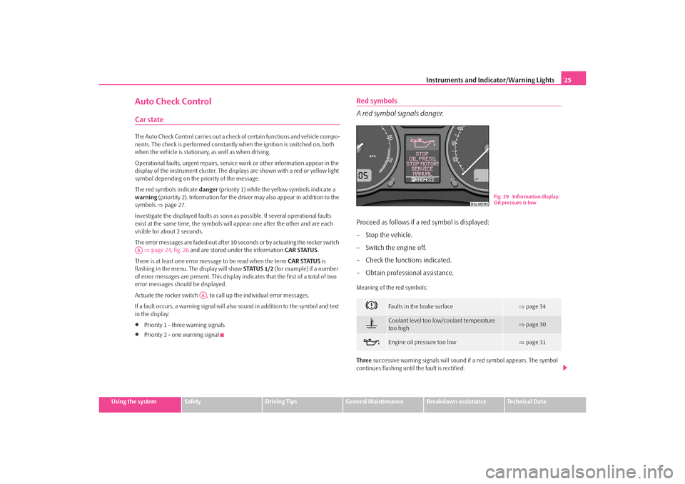
Auto Check ControlCar stateThe Auto Check Control carries out a check of certain functions and vehicle compo-
nents. The check is performed constantly when the ignition is switched on, both
when the vehicle is stationary, as well as when driving.
Operational faults, urgent repairs, service work or other information appear in the
display of the instrument cluster. The disp lays are shown with a red or yellow light
symbol depending on the priority of the message.
The red symbols indicate danger (priority 1) while the yellow symbols indicate a
warning (priortity 2). Information for the driver may also appear in addition to the
symbols ⇒page 27.
Investigate the displayed faults as soon as possible. If several operational faults
exist at the same time, the symbols will appear one after the other and are each
visible for about 2 seconds.
The error messages are faded out after 10 seconds or by actuating the rocker switch ⇒ page 24, fig. 26 and are stored under the information CAR STATUS.
There is at least one error message to be read when the term CAR STATUS is
flashing in the menu. The display will show STATUS 1/2 (for example) if a number
of error messages are present. This display indicates that the first of a total of two
error messages should be displayed.
Actuate the rocker switch , to call up the individual error messages.
If a fault occurs, a warning signal will also sound in addition to the symbol and text
in the display:•
Priority 1 - three warning signals
•
Priority 2 - one warning signal
Red symbols
A red symbol signals danger.Proceed as follows if a red symbol is displayed:
– Stop the vehicle.
– Switch the engine off.
– Check the functions indicated.
– Obtain professional assistance.Meaning of the red symbols:
Three successive warning signals will sound if a red symbol appears. The symbol
continues flashing until the fault is rectified.
AA
AA
Faults in the brake surface
⇒page 34
Coolant level too low/coolant temperature
too high
⇒page 30
Engine oil pressure too low
⇒page 31
Fig. 29 Information display:
Oil pressure is low
s2ig.book Page 25 Monday, November 10, 2008 11:20 AM
Page 29 of 226
Instruments and Indicator/Warning Lights
28
WARNING
•
If you do not pay attention to the wa rning lights coming on and the corre-
sponding descriptions and warning notes, this may result in severe body
injuries or major vehicle damage.
•
The engine compartment of your car is a hazardous area. There is a risk
of injuries, scalding, accidents and fire when working in the engine compartment, e.g. inspecting and replenis
hing oil and other fluids. It is also
essential to obse rve all warnings ⇒page 162.
Note
•
Arrangement of the indicator lights depends on the model and model version.
The symbols shown in the following function al description are to be found as indi-
cator lights in the instrument cluster.
•
Operational faults are shown in the inst rument cluster as red symbols (priority
1 - danger) or yellow symbols (priority 2 - warning).
Turn signal system
Either the left
or right
indicator light flashes depending on the position of the
turn signal lever.
The indicator light flashes at twice its normal rate if a turn signal light fails. This does
not apply when towing a trailer.
Switching off the hazard warning light system is switched on will cause all of the
turn signal lights as well as both indicator lights to flash.
Further information about the turn signal system ⇒page 52.
Turn signal system for vehicles towing a trailer
*
The warning light
flashes together with the other turn signal lights only if the
vehicle is towing a trailer.
The indicator light does not flash if a turn signal light on the trailer or on the vehicle
is not operating.
Airbag system*
⇒ page 30
Coolant temperature/coolant level
⇒page 30
Brake pad wear*
⇒page 31
Fuel reserve
⇒page 31
Engine oil
⇒page 31
Open door*
⇒page 32
Fluid level in windshield washer system*
⇒page 31
Antilock brake system (ABS)*
⇒page 32
Traction control system (TCS)*
⇒page 33
Electronic stability programme (ESP)*
⇒page 33
Dynamo
⇒page 33
Brake system
⇒page 34
Seat belt warning light*
⇒page 34
WARNING (continued)
s2ig.book Page 28 Monday, November 10, 2008 11:20 AM
Page 31 of 226
Instruments and Indicator/Warning Lights
30Glow plug system
(diesel engine)
The warning light
lights up for a cold engine when switching on the ignition
(pre-heat position) 2 ⇒ page 95. Start the engine just as soon as the indicator light
goes out.
The glow plug indicator light will come on for about 1 second if the engine is at a
normal operating temperature or if the outside temperature is above +5°C. This
means that you can start the engine right away.
There is a fault in the glow plug system if the warning light
does not come on
at all or lights up continuously . Contact a specialist garage as soon as possible to
obtain assistance.
If the warning light
begins to flash while driving, a fault exists in the engine
control. The engine management system selects an emergency programme which
enables you to drive to the nearest specialist garage by adopting a gentle style of
driving.
The following text will be displayed in the information display*:
ENGINE WORKSHOP!
Airbag system
Monitoring the airbag system
The warning light
comes on for a few seconds when the ignition is switched on.
There is a fault in the system if the warn ing light does not go out or comes on or
flashes while driving ⇒. This also applies if the warning light does not come on
when the ignition is switched on.
The following text will be displayed in the information display*:
AIRBAG FAULT
The functionality of the airbag system is also monitored electronically, when one
airbag has been switched off
Front airbag or side pass enger airbag deactivated us ing the diagnostic equip-
ment:
•
The warning light
lights up for 3 seconds after switching on the ignition and
then flashes again for 12 seconds.
Front passenger airbags switched off using the switch for front passenger
airbags* in storage compartment on the front passenger side:
•
The warning light
comes on for 3 seconds after the ignition has been
switched on.
•
The deactivation of the airb ag is indicated by the lighting up of the indicator
light
in the interior lighting ⇒page 123.
WARNING
Have the airbag system ch ecked immediately by a specialist garage if a fault
exists. Otherwise, there is a risk of th e airbag not being activated in the event
of an accident.
Note
Further information about switching off airbags ⇒page 122.Coolant temperature/ Coolant quantity
The warning light comes on for a few seconds
2) when the ignition is switched
on.
The coolant temperature is too high or the coolant level too low if the warning light
does not go out or flashes while driving.
3 peeps sound as an additional warning signal.
In this case stop and switch the engine off and check the coolant level; top up the
coolant as necessary.
Do not continue your journey if for some reason it is not possible under the
conditions prevailing to top up with coolant. Keep the engine switched off and 2)The warning light on vehicles fitted with information display does not come on after
switching the ignition on, but only if the coola nt temperature is too high or the coolant level
is too low.
s2ig.book Page 30 Monday, November 10, 2008 11:20 AM
Page 32 of 226
Instruments and Indicator/Warning Lights31
Using the system
Safety
Driving Tips
General Maintenance
Breakdown assistance
Technical Data
obtain professional assistance from a specialist garage, otherwise it could lead to
severe engine damage.
If the coolant is within the specified
range, the increased temperature may be
caused by an operating problem at the coolant fan. Check the fuse for the coolant
fan, replace it if necessary ⇒page 195, “Fuse assignment in engine compartment -
version 1” or ⇒ page 196, “Fuse assignment in en gine compartment - version 2”.
Do not continue driving if the warning light does not go off although the fluid is at
the correct level and also the fuse of the fa n is in proper order. Contact a specialist
garage to obtain assistance.
Please also refer to the additional instructions ⇒page 167, “Cooling system”.
The following text will be displayed in the information display*: STOP CHECK COOLANT SERVICE MANUAL
WARNING
•
If you must stop for technical reasons, then park the vehicle at a safe
distance from the traffic and switch off the engine and switch on the hazard
warning light system ⇒page 51.
•
Take care when opening the coolant expansion bottle. If the engine is
hot, the cooling system is pressurized - risk of scalding! It is best to allow the
engine to cool down before removing the cap.
•
Do not touch the coolant fan The coolant fan may switch on automati-
cally even if the ignition is off.
Thickness of the brake pads*
The warning light
comes on for a few seconds when the ignition is switched on.
If the warning light comes on, contact a specialist garage immediately and have
the brake pads on all of the wheels inspected.
A peep sounds as an addi tional warning signal.
The following text will be displayed in the information display*: CHECK BRAKE PADS
Windshield washer fluid level*
The warning light
comes on when the ignition is switched on if there is insuffi-
cient fluid in the windshield washer system. Top up with liquid ⇒page 174.
A peep sounds as an additional warning signal.
The following text will be displayed in the information display*: TOP UP WASH FLUID
Fuel reserve
The warning light
comes on, if the fuel level is still below 7 litres.
A peep sounds as an additional warning signal.
The following text will be displayed in the information display*: PLEASE REFUEL
Note
The Text in the information display* goes out only after refuelling and driving a
short distance.Engine oil
The warning light
lights up red (low oil pressure)
The warning light comes on for a few seconds when the ignition is switched on
3).
Stop the vehicle and switch the engine off if the warning light does not go off
within a few seconds after switching on the ignition or flashes while driving. Check
the oil level and top up with oil as necessary ⇒page 165.
3 peeps sound as an additional warning signal.
3)The warning light on vehicles fitted with information display does not come on after
switching the ignition on, but only if a fault exists or the engine oil level is too low.
s2ig.book Page 31 Monday, November 10, 2008 11:20 AM
Page 147 of 226
Towing a trailer
146should be attached to foldin g arms. Adjust the mirrors so that they provide you with
an adequate field of view to the rear.
Headlights
Before starting off with a hitched trailer, also check the setting of the headlights.
Alter the setting as necessary with the aid of the headlight beam adjuster
⇒ page 51.
Detachable ball head
The ball rod is detachable on vehicles wh ich feature a factory-fitted towing device.
It is stowed together with separate fitting instructions in the spare wheel well in the
luggage compartment of the vehicle.
Further information on the towing device ⇒page 147.
Note
•
We recommend that you also have yo ur vehicle inspected between service
intervals if you tow a trailer frequently.
•
The handbrake on the towing vehicle must be put on when coupling and
decoupling the trailer.
Driving Tips
Particular caution is required when towing a trailer.– Do not, as far as possible, drive with your vehicle unladen and the
trailer laden.
– Do not make full use of the legal maximum speeds. This applies in
particular to downhill sections.
– Apply the brakes in good time.
– Keep a check on the coolant temper ature gauge if the outside temper-
ature is high.
Distribution of weight
The distribution of the weight is very poor if your vehicle is unladen and the trailer
is laden. Maintain a particularly low speed if you cannot avoid driving with this
combination.
Driving speed
Do not drive faster than 80 km/hour for sa fety reasons. This also applies for coun-
tries in which higher speeds are allowed.
The fact that the driving stability of the vehicle + trailer combination reduces with
increasing speed means that the legally allowed speed should not be used when
there are unfavourable road, weather or wi nd conditions, particularly near acci-
dent black spots.
You must always reduce your speed immedi ately as soon as you detect even just
the slightest swaying of the trailer. On no account attempt to stop the trailer from
“swaying” by accelerating.
Apply the brakes in good time! If the trailer is fitted with a trailer brake, apply the
brakes gently at first and then brake firmly. This will avoid brake jolts resulting from
the trailer wheels locking. Shift down gears in good time before negotiating a
downhill section to allow the en gine to also act as a brake.
Engine overheating
Please keep a check on the coolant temperature gauge if you have to negotiate a
lengthy slope in a low gear at a high engi ne speed when the outside temperature is
very high ⇒page 16.
If the needle of the coolant temperature gauge moves into the right-hand area or
even the red area of the scale, reduce yo ur speed immediately. Stop and switch off
the engine if the warning light
in the instrument cluste r begins flashing. Wait a
few minutes and check the level of coolant in the coolant expansion bottle
⇒ page 167, “Inspecting the coolant level”.
Please refer to the following guidelines ⇒page 30, “Coolant temperature/ Coolant
quantity ”.
The coolant temperature can be reduced by switching on the heating.
Any increase in the cooling effect of the coolant fan through shifting down a gear
and increasing the engine speed is not possible since the fan speed is independent
s2ig.book Page 146 Monday, November 10, 2008 11:20 AM
Page 168 of 226
Inspecting and replenishing167
Using the system
Safety
Driving Tips
General Maintenance
Breakdown assistance
Technical Data
Check hydraulic oil
The hydraulic system of the power steering
is filled with the hydraulic oil desig-
nated in the catalogue as G 002 000.
Perform the inspection of the hydraulic oil level when the engine is cold and not
running.
The hydraulic oil level must be between the “MIN” and “MAX” markings
⇒ page 166, fig. 155 . If the level drops below the mark ing “MIN”, it is necessary that
the power steering is checked by a specialist garage. It is not sufficient to solely refill
with hydraulic oil.
Note
If the engine is not running (when towing) or if the V-ribbed belt is torn, the power
steering does not operate. The vehicle is fully steerable however. There is however
increased force required to turn the steering wheel.Cooling systemCoolant
The job of the coolant is to cool the engine.The cooling system does not require an y maintenance under normal operating
conditions. The coolant consists of water with a concentration of coolant additive
of 40 %. This mixture not only provides antifreeze protection down to -25°C but
also protects the cooling and heating system from corrosion. It also prevents the
formation of scale and significantly increases the boiling point of the coolant.
You must therefore not reduce the concentr ation of antifreeze agent in the coolant
by adding water, also not during the summ er months or in countries with a warm
climate. The concentration of coolant additive in the coolant must be at least
40%.
You can increase the amount of antifreeze in the coolant if a higher concentration
of antifreeze is necessary for climatic reasons but only up to 60% (antifreeze
protection down to approx. -40°C). The an tifreeze protection tails off above that
concentration. Vehicles exported to countries with a co
ld climate (e.g. Sweden, Norway, Finland)
are already factory-filled with a coolant which offers antifreeze protection down to
about -35°C. In these countries the concentr ation of coolant additive should be at
least 50 %.
Coolant
The cooling system is factory-filled with coolant (purple in colour), which complies
with the specification TL-VW 774 G.
We recommend that you use the same c oolant additive - G12 PLUS-PLUS (purple
in colour) for topping up the system.
Please contact a specialist garage if you have any questions regarding the coolant
or if you wish to fill up with a different coolant.
A specialist garage can also supply you with the correct coolant additives.
Caution
•
Other coolant additives may cause operational problems which, in partic-
ular, involves significantly reducing the anticorrosion effect.
•
Any faults or problems resulting from corrosion may cause a loss of
coolant and, as a consequence of th is, result in major engine damage.
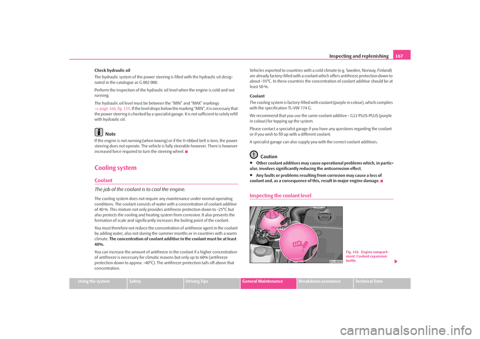
Inspecting the coolant level
Fig. 156 Engine compart-
ment: Coolant expansion
bottle
s2ig.book Page 167 Monday, November 10, 2008 11:20 AM
Page 169 of 226
Inspecting and replenishing
168
The coolant expansion bottle is loca ted in the engine compartment on
the right.
– Switch the engine off.
– Open the bonnet ⇒ in “Working in the engine compartment” on
page 162.
– Check the level of coolant in the coolant expansion bottle ⇒page 167, fig. 156 . When the engine is cold, the coolant level must
lie between the and markings. When the engine is warm, the
level may also lie slightly above the hatched part.If the coolant level in the reservoir is too low, this is indicated by the warning light
in the instrument cluster
⇒ page 30. We nevertheless recommend inspecting
the coolant level directly at th e reservoir from time to time.
Loss of coolant
A loss of coolant is first and foremost an indication of a leak in the system. You
should not merely top up the coolant in the reservoir. It is also important to have
the cooling system inspected without delay by a specialist garage.
Losses can only occur through the pressure relief in the cap of the coolant expan-
sion bottle which is completely free of leak s if the coolant boils as a result of over-
heating and is forced out of the cooling system.
WARNING
Read and observe the warning notes ⇒page 162, “Working in the engine
compartment” before working in the engine compartment.
Caution
One should contact a specialist garage as soon as possible if the source of over-
heating itself cannot be determined and removed, since there may be grave
damage to the engine.
Replenishing the coolant– Switch the engine off.
– Allow the engine to cool down.
– Place a cloth over the cap of the coolant expansion reservoir ⇒page 167, fig. 156 and unscrew the cap carefully by turning it to
the left ⇒.
– Top up the coolant.
– Screw the cap tight until it is heard to lock.The coolant which you use for replenishing the system, must comply with one
specific specification ⇒page 167, “Coolant”. Do not use an alternative additive if
the coolant additive G12 PLUS - PLUS is not av ailable in exceptional cases. Just top
up the system with water and as soon as possible arrange adjustment to correct the
mixing ratio of water and coolant additive again by a specialist garage.
Only use fresh coolant for topping up the system.
Do not top up the fluid above the hatched part. Excess coolant which is heated up
is forced out of the cooling system throug h the pressure relief valve in the cap of
the coolant compensation bottle.
Wait until the engine has cooled down for a system which has suffered a major loss
of coolant before pouring in coolant. This is necessary to avoid engine damage.
WARNING
•
The cooling system is pressurized! Do not open the cap of the coolant
expansion bottle if the engine is still hot - risk of scalding!
•
The coolant additive and thus all of the coolant is harmful to your health.
Avoid contact with the coolant. Coolant vapours are also harmful to the
health. It is important, therefore, to always safely store any coolant additive
in its original container out of the reach of children - risk of poisoning!
•
If any splashes of coolant get into yo ur eyes, rinse out your eyes immedi-
ately with clear water and contact a doctor as soon as possible.
Aa
Ab
s2ig.book Page 168 Monday, November 10, 2008 11:20 AM
Page 170 of 226
Inspecting and replenishing169
Using the system
Safety
Driving Tips
General Maintenance
Breakdown assistance
Technical Data
•
You should also consult a doctor without delay if you have inadvertently
swallowed coolant.Caution
Do not continue your journey if for some reason it is not possible under the
conditions prevailing to top up with coolant. Switch of the engine and contact
and obtain professional assistance from a specialist garage.
For the sake of the environment
Do not re-use coolant if it is necessary to drain the coolant in the system. It should
be collected and disposed of in comp liance with environmental protection
regulations.Radiator fan
The radiator fan may switch on suddenly.The radiator fan is driven by an electric motor and controlled according to the
coolant temperature.
The radiator fan may continue running fo r up to 10 minutes after the engine has
been switched off - even if the ignition is also off. It may also switch on suddenly
after a certain time, if•
the coolant temperature has risen beca use of an accumulation of heat or
•
the warm engine compartment is heated up additionally by strong sunlight.
WARNING
You must therefore be aware when work ing in the engine compartment that
the fan may switch on suddenly - risk of injury!
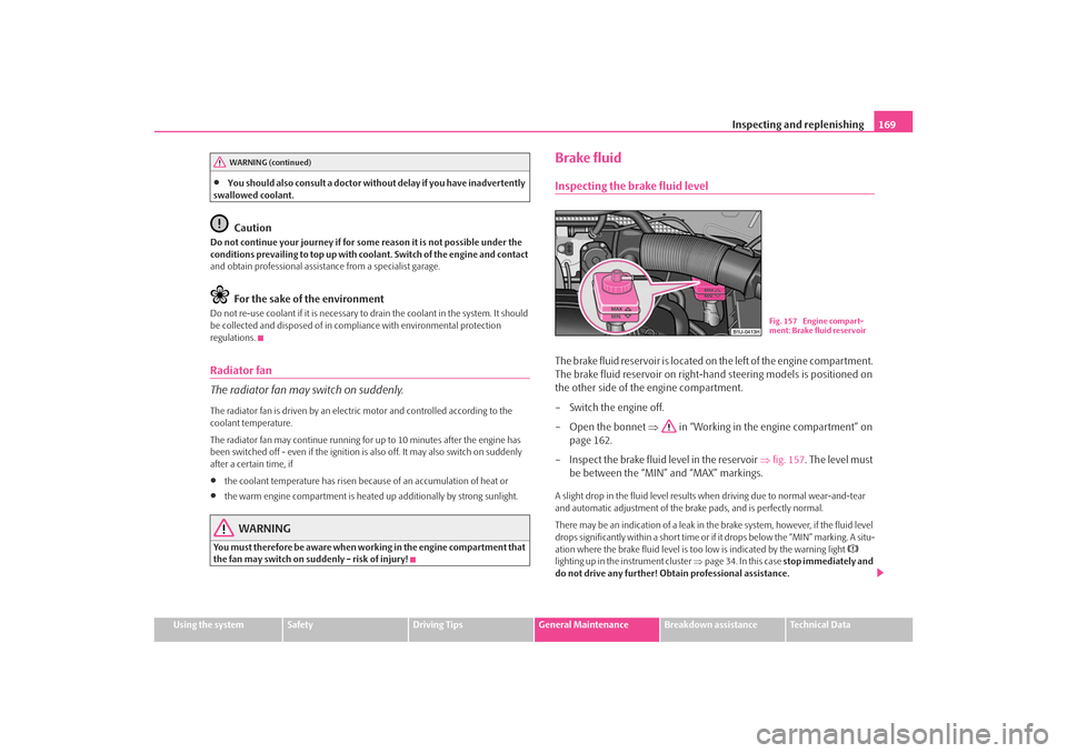
Brake fluidInspecting the brake fluid levelThe brake fluid reservoir is located on the left of the engine compartment.
The brake fluid reservoir on right-hand steering models is positioned on
the other side of the engine compartment.
– Switch the engine off.
– Open the bonnet ⇒ in “Working in the engine compartment” on
page 162.
– Inspect the brake fluid level in the reservoir ⇒fig. 157 . The level must
be between the “MIN” and “MAX” markings.A slight drop in the fluid level results when driving due to normal wear-and-tear
and automatic adjustment of the br ake pads, and is perfectly normal.
There may be an indication of a leak in the brake system, however, if the fluid level
drops significantly within a short time or if it drops below the “MIN” marking. A situ-
ation where the brake fluid level is too low is indicated by the warning light
lighting up in the instrument cluster ⇒page 34. In this case stop immediately and
do not drive any further! Obtain professional assistance.
WARNING (continued)
Fig. 157 Engine compart-
ment: Brake fluid reservoir
s2ig.book Page 169 Monday, November 10, 2008 11:20 AM
Page 219 of 226
Index
218Child seat . . . . . . . . . . . . . . . . . . . . . . . . . . . . . . . . . . . 128
Classification into groups . . . . . . . . . . . . . . . . . 128
ISOFIX system . . . . . . . . . . . . . . . . . . . . . . . . . . . . 131
Use of child safety seats . . . . . . . . . . . . . . . . . . 128
Children and safety . . . . . . . . . . . . . . . . . . . . . . . . . . 125
Chrome parts . . . . . . . . . . . . . . . . . . . . . . . . . . . . . . . 151
Cigarette lighter . . . . . . . . . . . . . . . . . . . . . . . . . . . . . . 78
Cleaning . . . . . . . . . . . . . . . . . . . . . . . . . . . . . . . . . . . . 149
Climatronic Defrosting windows . . . . . . . . . . . . . . . . . . . . . . . 91
Recirculated air mode . . . . . . . . . . . . . . . . . . . . . 92
Setting temperature . . . . . . . . . . . . . . . . . . . . . . . 92
Climatronic (automatic air conditioning) . . . . . . . 89
Clock . . . . . . . . . . . . . . . . . . . . . . . . . . . . . . . . . . . . . . . . 19
Clothes hooks . . . . . . . . . . . . . . . . . . . . . . . . . . . . . . . . 82
Cockpit General view . . . . . . . . . . . . . . . . . . . . . . . . . . . . . . . 9
Compartments . . . . . . . . . . . . . . . . . . . . . . . . . . . . . . . 79
Computer . . . . . . . . . . . . . . . . . . . . . . . . . . . . . . . . . . . . 19
Convenience operation . . . . . . . . . . . . . . . . . . . . . . . 45
Converting/masking over headlights . . . . . . . . . . 144
Coolant . . . . . . . . . . . . . . . . . . . . . . . . . . . . . . . . . . . . . 167 replenishing . . . . . . . . . . . . . . . . . . . . . . . . . . . . . 168
Warning light . . . . . . . . . . . . . . . . . . . . . . . . . . . . . 30
Coolant level Warning light . . . . . . . . . . . . . . . . . . . . . . . . . . . . . 30
Coolant quantity Warning light . . . . . . . . . . . . . . . . . . . . . . . . . . . . . 30
Coolant temperature gauge . . . . . . . . . . . . . . . . . . . 16
Coolant temperature/coolant level Warning light . . . . . . . . . . . . . . . . . . . . . . . . . . . . . 30
Correct seated position . . . . . . . . . . . . . . . . . . . . . . 106 Counter for distance driven . . . . . . . . . . . . . . . . . . . . 18
Cruise control system . . . . . . . . . . . . . . . . . . . . . . . . . . 99
Cup holder
front . . . . . . . . . . . . . . . . . . . . . . . . . . . . . . . . . . . . . . 76
DDeactivatingan airbag . . . . . . . . . . . . . . . . . . . . . . . . . . . . . . . . 122
Deactivating an airbag . . . . . . . . . . . . . . . . . . . . . . . 122
Defrosting rear window . . . . . . . . . . . . . . . . . . . . . . . . 54
De-icing the windows . . . . . . . . . . . . . . . . . . . . . . . 152
Detachable towing device . . . . . . . . . . . . . . . . . . . 147
Diesel . . . . . . . . . . . . . . . . . . . . . . . . . . . . . . . . . . . . . . 157
Diesel engines Starting the engine . . . . . . . . . . . . . . . . . . . . . . . . . 96
Digital clock . . . . . . . . . . . . . . . . . . . . . . . . . . . . . . . . . . 19
Direction indicators . . . . . . . . . . . . . . . . . . . . . . . . . . . 52 Warning light . . . . . . . . . . . . . . . . . . . . . . . . . . . . . . 28
Display . . . . . . . . . . . . . . . . . . . . . . . . . . . . . . . . . . . . . . . 23
Distance driven . . . . . . . . . . . . . . . . . . . . . . . . . . . . . . . 18
Door Child safety lock . . . . . . . . . . . . . . . . . . . . . . . . . . . 37
Driving economically . . . . . . . . . . . . . . . . . . . . . . . . 140EEDL . . . . . . . . . . . . . . . . . . . . . . . . . . . . . . . . . . . . . . . . 134
Electric power-operated window Operational faults . . . . . . . . . . . . . . . . . . . . . . . . . 46
Electric sliding/tilting roof . . . . . . . . . . . . . . . . . . . . . . 46
Electrically adjustable exterior mirror . . . . . . . . . . . 58
Electronic Differential Lock . . . . . . . . . . . . . . . . . . . 134 Electronic immobiliser . . . . . . . . . . . . . . . . . . . . . 29, 36
Warning light . . . . . . . . . . . . . . . . . . . . . . . . . . . . . 29
Electronic stability programme . . . . . . . . . . . . . . . . 133
Electronic stability programme (ESP) Warning light . . . . . . . . . . . . . . . . . . . . . . . . . . . . . 33
Engine starting . . . . . . . . . . . . . . . . . . . . . . . . . . . . . . . . . . . 95
switching off . . . . . . . . . . . . . . . . . . . . . . . . . . . . . . 97
Engine compartment Safety information . . . . . . . . . . . . . . . . . . . . . . . . 162
Engine electronics Warning light . . . . . . . . . . . . . . . . . . . . . . . . . . . . . 29
Engine oil . . . . . . . . . . . . . . . . . . . . . . . . . . . . . . . . . . . 164 Changing . . . . . . . . . . . . . . . . . . . . . . . . . . . . . . . . 166
changing . . . . . . . . . . . . . . . . . . . . . . . . . . . . . . . . 166
check . . . . . . . . . . . . . . . . . . . . . . . . . . . . . . . . . . . . 165
replenishing . . . . . . . . . . . . . . . . . . . . . . . . . . . . . 165
Warning light . . . . . . . . . . . . . . . . . . . . . . . . . . . . . 31
Engine revolutions counter . . . . . . . . . . . . . . . . . . . . 16
Environment . . . . . . . . . . . . . . . . . . . . . . . . . . . . . . . . 140
Environmental compatibility . . . . . . . . . . . . . 140, 143
ESP . . . . . . . . . . . . . . . . . . . . . . . . . . . . . . . . . . . . . . . . . 133 Warning light . . . . . . . . . . . . . . . . . . . . . . . . . . . . . 33
Exhaust gas Warning light . . . . . . . . . . . . . . . . . . . . . . . . . . . . . 29
Exhaust gas inspection Warning light . . . . . . . . . . . . . . . . . . . . . . . . . . . . . 29
Explanations . . . . . . . . . . . . . . . . . . . . . . . . . . . . . . . . . . . 6
Exterior mirror . . . . . . . . . . . . . . . . . . . . . . . . . . . . . . . . 58
Exterior mirror heater . . . . . . . . . . . . . . . . . . . . . . . . . 58
s2ig.book Page 218 Monday, November 10, 2008 11:20 AM