fuel consumption SKODA OCTAVIA TOUR 2009 1.G / (1U) Owner's Manual
[x] Cancel search | Manufacturer: SKODA, Model Year: 2009, Model line: OCTAVIA TOUR, Model: SKODA OCTAVIA TOUR 2009 1.G / (1U)Pages: 226, PDF Size: 13.11 MB
Page 1 of 226
SIMPLY CLEVER
ŠkodaOctavia Tour
OWNER‘S MANUAL
How you can contribute to a cleaner environment
The fuel consumption of your Škoda - and thus the level of
pollutants contained in the exhaust - is also determined by
how you drive.
The noise level and wear and tear are also influenced by how
you personally handle your vehicle. This Owner ´s Manual tells
you how to drive your Škoda to achieve the minimum impact
on the environment, and how to save money at the same time.
Look up „Environment“ in the Index to find out more.
Please also refer to all the texts identified with a
in this
Owner ´s Manual.
Make your contribution - for the sake of the
environment.
www.skoda-auto.com
Návod k obsluze
Octavia Tour anglicky 01.09
S63.5610.34.20
1U0 012 003 KT
Octavia Tour anglicky 01.09
11_08.indd 1
11_08.indd 1 3.9.2008 12:55:34
3.9.2008 12:55:34
Page 5 of 226
Contents
4Driving Tips
. . . . . . . . . . . . . . . . . . . . . . . . . . . . . .
Intelligent Technology
. . . . . . . . . . . . . . . . . . . . . . . .
Electronic stability programme (ESP)* . . . . . . . . . .
Brakes . . . . . . . . . . . . . . . . . . . . . . . . . . . . . . . . . . . . . . .
Brake booster . . . . . . . . . . . . . . . . . . . . . . . . . . . . . . . .
Antilock brake system (ABS)* . . . . . . . . . . . . . . . . . .
Brake Assist* . . . . . . . . . . . . . . . . . . . . . . . . . . . . . . . . .
Driving and the Environment
. . . . . . . . . . . . . . . . .
The first 1 500 kilometres and then afterwards . .
Catalytic converter . . . . . . . . . . . . . . . . . . . . . . . . . . . .
Driving in an economical and environmentally
conscious manner . . . . . . . . . . . . . . . . . . . . . . . . . . . .
Environmental compatibility . . . . . . . . . . . . . . . . . . .
Motoring abroad . . . . . . . . . . . . . . . . . . . . . . . . . . . . .
Avoiding damage to your vehicle . . . . . . . . . . . . . .
To w i n g a t r a i l e r
. . . . . . . . . . . . . . . . . . . . . . . . . . . . . . . .
Towing a trailer . . . . . . . . . . . . . . . . . . . . . . . . . . . . . . .
Detachable towing device* . . . . . . . . . . . . . . . . . . . .
General Maintenance
. . . . . . . . . . . . . . .
Taking care of your ve hicle and cleaning the
vehicle
. . . . . . . . . . . . . . . . . . . . . . . . . . . . . . . . . . . . . . . . .
General . . . . . . . . . . . . . . . . . . . . . . . . . . . . . . . . . . . . . .
Care of the exterior of vehicle . . . . . . . . . . . . . . . . . .
Care of the interior of vehicle . . . . . . . . . . . . . . . . . .
Fuel
. . . . . . . . . . . . . . . . . . . . . . . . . . . . . . . . . . . . . . . . . . . .
Petrol . . . . . . . . . . . . . . . . . . . . . . . . . . . . . . . . . . . . . . . .
Diesel . . . . . . . . . . . . . . . . . . . . . . . . . . . . . . . . . . . . . . .
Refuelling . . . . . . . . . . . . . . . . . . . . . . . . . . . . . . . . . . . .
Emergency release of fuel filler flap . . . . . . . . . . . .
Inspecting and replenishing
. . . . . . . . . . . . . . . . . .
Engine compartment . . . . . . . . . . . . . . . . . . . . . . . . .
Engine oil . . . . . . . . . . . . . . . . . . . . . . . . . . . . . . . . . . . .
Cooling system . . . . . . . . . . . . . . . . . . . . . . . . . . . . . . .
Brake fluid . . . . . . . . . . . . . . . . . . . . . . . . . . . . . . . . . . . Battery . . . . . . . . . . . . . . . . . . . . . . . . . . . . . . . . . . . . . . .
Windshield washer system . . . . . . . . . . . . . . . . . . . .
Wheels and Tyres
. . . . . . . . . . . . . . . . . . . . . . . . . . . . . .
Wheels . . . . . . . . . . . . . . . . . . . . . . . . . . . . . . . . . . . . . .
Accessories, changes and replacement of partsAccessories and replacement parts . . . . . . . . . . . . .
Technical changes . . . . . . . . . . . . . . . . . . . . . . . . . . . .Breakdown assistance
. . . . . . . . . . . . . .
Breakdown assistance
. . . . . . . . . . . . . . . . . . . . . . . .
First-aid box*, Warning triangle* and bulb set . . .
Fire extinguisher* . . . . . . . . . . . . . . . . . . . . . . . . . . . . .
Vehicle tool kit . . . . . . . . . . . . . . . . . . . . . . . . . . . . . . . .
Spray for repairing a tyre* . . . . . . . . . . . . . . . . . . . . .
Tyre repair kit* . . . . . . . . . . . . . . . . . . . . . . . . . . . . . . . .
Spare wheel . . . . . . . . . . . . . . . . . . . . . . . . . . . . . . . . . .
Changing a wheel . . . . . . . . . . . . . . . . . . . . . . . . . . . . .
Jump-starting . . . . . . . . . . . . . . . . . . . . . . . . . . . . . . . .
Tow-starting and towing vehicle . . . . . . . . . . . . . . .
Fuses and light bulbs
. . . . . . . . . . . . . . . . . . . . . . . . . .
Electric fuses . . . . . . . . . . . . . . . . . . . . . . . . . . . . . . . . .
Bulbs . . . . . . . . . . . . . . . . . . . . . . . . . . . . . . . . . . . . . . . .
Technical Data
. . . . . . . . . . . . . . . . . . . . . . . . . .
Technical Data
. . . . . . . . . . . . . . . . . . . . . . . . . . . . . . . . .
General information . . . . . . . . . . . . . . . . . . . . . . . . . .
Used abbreviations . . . . . . . . . . . . . . . . . . . . . . . . . . .
Performances . . . . . . . . . . . . . . . . . . . . . . . . . . . . . . . .
Weight . . . . . . . . . . . . . . . . . . . . . . . . . . . . . . . . . . . . . . .
Identification details . . . . . . . . . . . . . . . . . . . . . . . . . .
Fuel consumption according to the regulations
(99/100/EU) . . . . . . . . . . . . . . . . . . . . . . . . . . . . . . . . . .
Dimensions . . . . . . . . . . . . . . . . . . . . . . . . . . . . . . . . . .
1.4 ltr./55 kW - EU4 . . . . . . . . . . . . . . . . . . . . . . . . . . .
1.6 ltr./75 kW - EU4/EU2 DDK . . . . . . . . . . . . . . . . . .
1.8 ltr./110 kW - EU4/EU3D . . . . . . . . . . . . . . . . . . . . 1.9 ltr./66 kW TDI - EU3 . . . . . . . . . . . . . . . . . . . . . . . .
1.9 ltr./74 kW TDI PD - EU4 . . . . . . . . . . . . . . . . . . . .
Vehicles of the Octavia Combi group N1 . . . . . . . .
Vehicles of the Octavia Combi group - Vehicles for
reconstruction . . . . . . . . . . . . . . . . . . . . . . . . . . . . . . . .
Index
. . . . . . . . . . . . . . . . . . . . . . . . . . . . . . . . . . . . . . . .
133
133
133
135
136
137
137
139
139
140
140
143
144
144
145
145
147
149
149
149
149
154
157
157
157
158
159
161
161
164
167
169 170
174
175
175
181
181
181
183
183
183
183
184
184
184
185
185
190
191
194
194
197
203
203
203
203
203
203
203
204
205
206
208
210212
214
216
216
217
s2ig.book Page 4 Monday, November 10, 2008 11:20 AM
Page 7 of 226
Layout of this Owner's Manual (explanations)
6Layout of this Owner's Manual (explanations)The Owner's Manual has been systematically designed, in order to make it easy for
you to find and absorb the information you require.Chapters, table of contents and subject indexThe text of the manual are divided into relatively short sections which are
combined into easy-to-read chapters. The chapter you are reading at any partic-
ular moment is highlighted at the bottom right of the page.
The Table of contents is arranged according to the chapters and the detailed
Subject index at the end of the Owner's Manual helps you to rapidly find the infor-
mation you are looking for.SectionsThe majority of Sections apply to all models.
Since there is a wide range of different equipment and options available it is clearly
unavoidable, despite dividing the contents into sections, that mention may be
made of equipment which is not fitted to your vehicle.Brief information and instructionsEach section has a Heading.
This is followed by Brief information (in large italic lettering), which tells you the
subject which is dealt with in this section.
Most of the illustrations are accompanied by an Instruction (in relatively large
letters) which explains to you in a straig htforward way the action you have to take.
Work steps which have to be carried out are illustrated with a hyphen.Direction indicationsAll direction indications such as “left”, “right ”, “front”, “rear” relate to the direction
of travel of the vehicle.Explanation of symbols* Equipment which is marked in such a wa y is only standard on certain vehicle
model versions or only suppliable as optional equipment for certain models. End of a section.
The section is continued on the next page.NotesAll four kinds of notes, which are used in th e text, are always stated at the end of the
respective section.
WARNING
The most important notes are marked with the heading WARNING. These
WARNING notes draw your attention to a serious risk of accident or injury.
While reading the text you will frequently encounter a double arrow
followed by a small warning symbol. This symbol is intended to draw your
attention to a WARNING note at the end of the section to which you must pay
careful attention.
Caution
A Caution note draws your attention to the possibility of damage to your vehicle
(e.g. damage to gearbox), or points out general risks of an accident.
For the sake of the environment
An Environmental note draws your attention to environmental protection
aspects. This is where you will, for example, find tips aimed at reducing your fuel
consumption.
Note
A normal Note draws your attention in a general way to important information.
s2ig.book Page 6 Monday, November 10, 2008 11:20 AM
Page 21 of 226
Instruments and Indicator/Warning Lights
20The multi-functional indicator offers you a range of useful information.
Note
In certain national versions the displays appear in the Imperial system of
measures.MemoryThe multi-functional indicator is eq uipped with two automatic memories.
The data of the single-trip memory (memory 1) is shown if a 1 appears in the
display. A 2 shown in the display means that da ta relates to the total distance
memory (memory 2).
Switching of the memory takes place when the button ⇒fig. 21 .
Single-trip memory (memory 1)
The single-trip memory collates the driving information from the moment the igni-
tion is switched on until it is switched off. New data will also flow into the calcula-
tion of the current driving information if the trip is continued within 2 hours after
switching off the ignition. The memory will be is automatically erased, on the other
hand, if the trip is interrupted for more than 2 hours. Total-trip memory (memory 2)
The total distance driven memory gathers
data from any number of individual jour-
neys up to a total of 99 hours and 59 minutes driving or 9.999 kilometres driven.
The memory is deleted when either of these limits is reached and the calculation
starts from anew.
The total-trip memory will not, contrary to the single-trip memory, be deleted after
a period of interruption of driving of 2 hours.
Note
All information in the memory is erased if the battery of the vehicle is
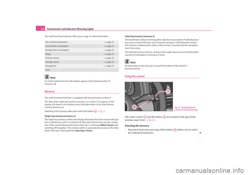
disconnected.Using the systemThe rocker switch and the button are located in the grip of the
window wiper lever ⇒fig. 21 .
Selecting the memory
– Repeated short-term pressing of th e button allows one to select
the individual memories.
The outside temperature
⇒ page 21
Current fuel consumption
⇒page 21
Average fuel consumption
⇒page 22
Range
⇒page 22
Distance driven
⇒page 22
Average speed
⇒page 22
Driving time
⇒page 22
Time
AB
Fig. 21 Multi-functional
indicator: Control elements
AA
AB
AB
s2ig.book Page 20 Monday, November 10, 2008 11:20 AM
Page 22 of 226
Instruments and Indicator/Warning Lights21
Using the system
Safety
Driving Tips
General Maintenance
Breakdown assistance
Technical Data
Selecting the functions
– Press the rocker switch up or down. This will cause the individual
functions of the multi-f unctional indicator to appear in the display
one after the other.
Setting function to zero
– Select the memory you want.
– Press button for more than 1 second.The following readouts of the selected me mory will be set to zero by button :•
average fuel consumption,
•
distance driven,
•
average speed,
•
Driving time.
You can only operate the multi-functional indicator when the ignition is switched
on. After the ignition is switched on, the fu nction displayed is the one which you last
selected before switching off the ignition.
If the outside temperature drops below +4 °C, the outside temperature indicator
with a snow flake symbol appears. The symbol warns the driver of the possible
danger of ice on the road. After the rock er switch is pressed, the function
displays the one which you last selected before switching off the ignition.
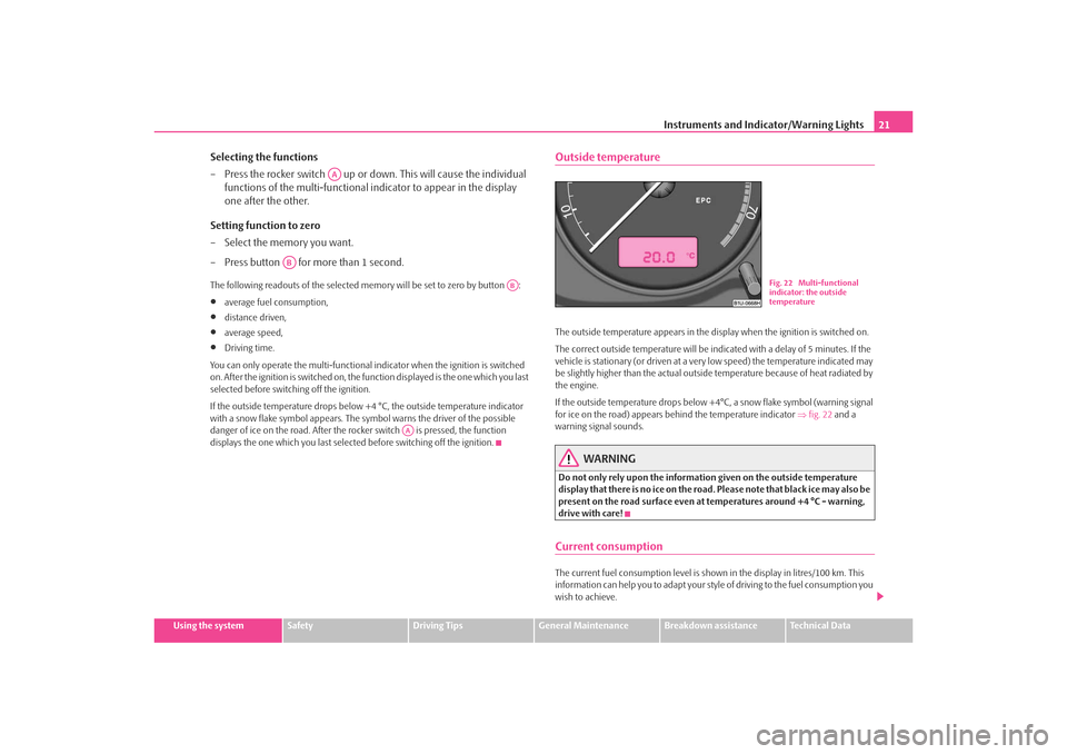
Outside temperatureThe outside temperature appears in the disp lay when the ignition is switched on.
The correct outside temperature will be indicated with a delay of 5 minutes. If the
vehicle is stationary (or driven at a very low speed) the temperature indicated may
be slightly higher than the actual outsid e temperature because of heat radiated by
the engine.
If the outside temperature drops below +4°C , a snow flake symbol (warning signal
for ice on the road) appears be hind the temperature indicator ⇒fig. 22 and a
warning signal sounds.
WARNING
Do not only rely upon the information given on the outside temperature
display that there is no ice on the road. Please note that black ice may also be
present on the road surface even at te mperatures around +4 °C - warning,
drive with care!Current consumptionThe current fuel consumption level is shown in the display in litres/100 km. This
information can help you to adapt your styl e of driving to the fuel consumption you
wish to achieve.
AA
AB
AB
AA
Fig. 22 Multi-functional
indicator: the outside
temperature
s2ig.book Page 21 Monday, November 10, 2008 11:20 AM
Page 23 of 226
Instruments and Indicator/Warning Lights
22The display appears in litres/hour if the vehicle is stationary or driving at a low
speed.Average fuel consumptionThe average fuel consumption since the memory was last erased is shown in the
display in litres/100 km ⇒page 20. This information can help you to adapt your
style of driving to the fuel co nsumption you wish to achieve.
If you wish to determine the average fuel consumption over a certain period of time
you must first erase the memory at the start of the new measurement using the
button ⇒page 20, fig. 21 . A zero appears in the display for the first 300 m you
drive after erasing the memory.
The indicated value will be updated every 5 seconds while you are driving.
Note
The amount of fuel consumed will not be indicated.RangeThe estimated range in kilometres is shown on the display. It indicates the distance
you can still drive with your vehicle based on the present level of fuel in the tank for
the same style of driving. The readout is shown in steps of 10 km.
The fuel consumption for the last 50 km is taken as a basis for calculating the range.
If you drive in a more economical manner from this moment on, the range will be
increased accordingly.
You first drive 50 km if the readout is reset (after disconnecting the battery) before
a new readout for the range is displayed.Distance drivenThe distance driven since the memory was last erased appears in the display
⇒ page 20. If you wish to calculate the distance driven from a particular time of day you must first erase the memory at this mo
ment in time by pressing the button
⇒ page 20, fig. 21 .
The maximum distance indica ted in both switch positions is 9.999 km. The indi-
cator is set back to null if this period is exceeded.
Average speedThe average speed since the memory was last erased is shown in the display in
km/hour ⇒page 20. If you wish to determine the average speed over a certain
period of time you must first erase the memory at the start of the new measure-
ment using the button ⇒page 20, fig. 21 .
A zero appears in the display for the first 300 m you drive after erasing the memory.
The indicated value will be updated every 5 seconds while you are driving.Driving timeThe driving time which has elapsed since the memory was last erased, appears in
the display ⇒page 20. If you wish to calculate th e driving time from a particular
time of day you must first erase the memory at this moment in time by pressing the
button ⇒page 20, fig. 21 .
The maximum distance indi cated in both memories is 99 hours and 59 minutes.
The indicator is set back to null if this period is exceeded.Warning against excessive speeds*An acoustic warning signal will sound when the vehicle speed exceeds 120 kilome-
tres per hour. The acoustic warning signal will switch off again when the vehicle
speed goes below this speed limit.
This function is only vali d for some export countries.
AB
AB
AB
AB
s2ig.book Page 22 Monday, November 10, 2008 11:20 AM
Page 55 of 226
Lights and Visibility
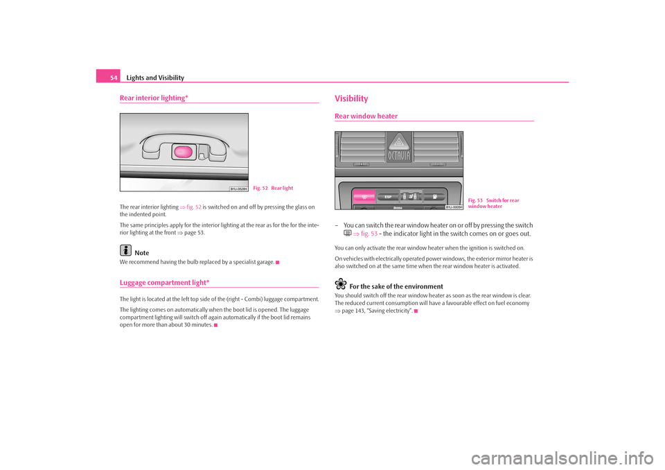
54Rear interior lighting*The rear interior lighting ⇒fig. 52 is switched on and off by pressing the glass on
the indented point.
The same principles apply for the interior lighting at the rear as for the for the inte-
rior lighting at the front ⇒page 53.
Note
We recommend having the bulb re placed by a specialist garage.Luggage compartment light*The light is located at the left top side of the (right - Combi) luggage compartment.
The lighting comes on automatically when the boot lid is opened. The luggage
compartment lighting will switch off agai n automatically if the boot lid remains
open for more than about 30 minutes.
VisibilityRear window heater– You can switch the rear window heater on or off by pressing the switch
⇒ fig. 53 - the indicator light in the switch comes on or goes out.
You can only activate the rear window he ater when the ignition is switched on.
On vehicles with electrically operated power windows, the exterior mirror heater is
also switched on at the same time when the rear window heater is activated.
For the sake of the environment
You should switch off the rear window heater as soon as the rear window is clear.
The reduced current consumption will have a favourable effect on fuel economy
⇒ page 143, “Saving electricity”.
Fig. 52 Rear light
Fig. 53 Switch for rear
window heater
s2ig.book Page 54 Monday, November 10, 2008 11:20 AM
Page 76 of 226
Seats and Storage75
Using the system
Safety
Driving Tips
General Maintenance
Breakdown assistance
Technical Data
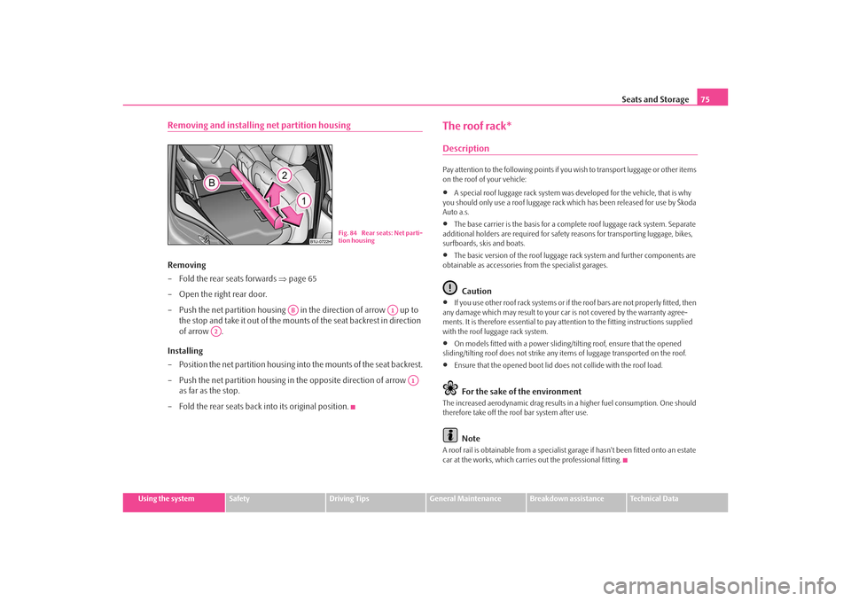
Removing and installing net partition housingRemoving
– Fold the rear seats forwards ⇒page 65
– Open the right rear door.
– Push the net partition housing in the direction of arrow up to the stop and take it out of the mounts of the seat backrest in direction
of arrow .
Installing
– Position the net partition housing in to the mounts of the seat backrest.
– Push the net partition housing in the opposite direction of arrow as far as the stop.
– Fold the rear seats back into its original position.
The roof rack*DescriptionPay attention to the following points if yo u wish to transport luggage or other items
on the roof of your vehicle:•
A special roof luggage rack system was developed for the vehicle, that is why
you should only use a roof luggage rack which has been released for use by Škoda
Auto a.s.
•
The base carrier is the basis for a comple te roof luggage rack system. Separate
additional holders are required for safety reasons for transporting luggage, bikes,
surfboards, skis and boats.
•
The basic version of the roof luggage rack system and further components are
obtainable as accessories from the specialist garages.Caution
•
If you use other roof rack sy stems or if the roof bars are not properly fitted, then
any damage which may result to your ca r is not covered by the warranty agree-
ments. It is therefore essential to pay attention to the fitting instructions supplied
with the roof luggage rack system.
•
On models fitted with a power sliding/tilting roof, ensure that the opened
sliding/tilting roof does not strike any items of luggage transported on the roof.
•
Ensure that the opened boot lid does not collide with the roof load.For the sake of the environment
The increased aerodynamic drag results in a higher fuel consumption. One should
therefore take off the roof bar system after use.
Note
A roof rail is obtainable from a specialist garage if hasn't been fitted onto an estate
car at the works, which carries out the professional fitting.
Fig. 84 Rear seats: Net parti-
tion housing
AB
A1
A2
A1
s2ig.book Page 75 Monday, November 10, 2008 11:20 AM
Page 89 of 226
Heating and air conditioning system
88Recirculated air mode
In recirculated air mode air is sucked out of the interior of the vehicle
and then fed back into the interior.Recirculated air mode prevents polluted air outside the vehicle from
getting into the vehicle, for example when driving through a tunnel or
when standing in a traffic jam.
Switching recirculated air mode on
– Press the button ⇒page 86, fig. 101 - the warning light lights up
in the button.
Switching recirculated air mode off
– Press again the button - the warning light in the button goes out.The button cannot be pressed if the control dial is in the position
or close
to this position.
WARNING
You should not leave recirculated air mode on over a longer period of time,
as “stale” air may result in fatigue in the driver and occupants, divert your
attention and also cause the windows to mist up. The risk of having an acci-
dent increases. Switch recirculated air mode off as soon as the windows
begin misting up.Using the air conditioning system economicallyThe compressor on the air co nditioning system uses power from the engine when
in cooling mode which will effect the fuel consumption.
It recommended to open the windows or the doors of a vehicle for which the inte-
rior has been strongly heated through the effect of direct sunlight in order to allow
the heated air to escape.
The cooling system should not be switched on while travelling when the window is
open.
The desired interior temperature can also be achieved without switching in the
cooling system just by switching to fresh air mode.
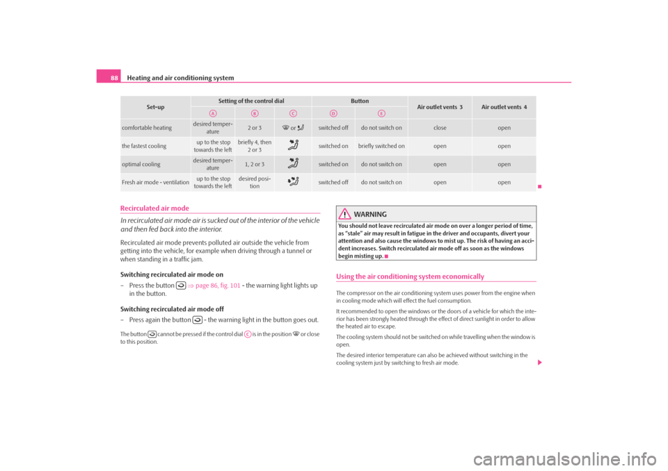
comfortable heating
desired temper- ature
2 or 3
or
switched off
do not switch on
close
open
the fastest cooling
up to the stop
towards the left
briefly 4, then 2or 3
switched on
briefly switched on
open
open
optimal cooling
desired temper- ature
1, 2 or 3
switched on
do not switch on
open
open
Fresh air mode - ventilation
up to the stop
towards the left
desired posi- tion
switched off
do not switch on
open
open
Set-up
Setting of the control dial
Button
Air outlet vents 3
Air outlet vents 4
AA
AB
AC
AD
AE
AC
s2ig.book Page 88 Monday, November 10, 2008 11:20 AM
Page 96 of 226
Starting-off and Driving95
Using the system
Safety
Driving Tips
General Maintenance
Breakdown assistance
Technical Data
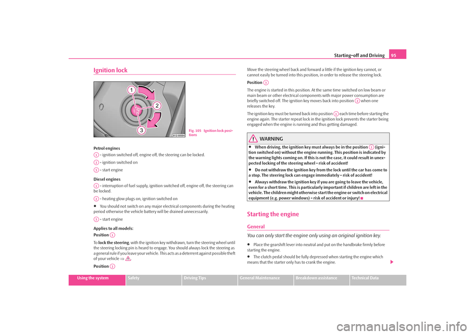
Ignition lockPetrol engines
- ignition switched off, engine off, the steering can be locked.
- ignition switched on
- start engine
Diesel engines - interruption of fuel supply, ignition switched off, engine off, the steering can
be locked.
- heating glow plugs on, ignition switched on•
You should not switch on any major elec trical components during the heating
period otherwise the vehicle batter y will be drained unnecessarily.
- start engine
Applies to all models:
Position
To lock the steering , with the ignition key withdrawn, turn the steering wheel until
the steering locking pin is heard to engage. You should always lock the steering as
a general rule if you leave your vehicle. This acts as a deterrent against possible theft
of your vehicle ⇒.
Position Move the steering wheel back and forward a little if the ignition key cannot, or
cannot easily be turned into
this position, in order to release the steering lock.
Position
The engine is started in this position. At the same time switched on low beam or
main beam or other electrical compon ents with major power consumption are
briefly switched off. The ignition key moves back into position when one
releases the key.
The ignition key must be turned back into position each time before starting the
engine again. The starter repeat lock in th e ignition lock prevents the starter being
engaged when the engine is running and thus getting damaged.
WARNING
•
When driving, the ignition key must always be in the position (igni-
tion switched on) without the engine running. This position is indicated by
the warning lights coming on. If this is not the case, it could result in unex-
pected locking of the steering wheel - risk of accident!
•
Do not withdraw the ignition key from the lock until the car has come to
a stop. The steering lock can engage immediately - risk of accident!
•
Always withdraw the ignition key if you are going to leave the vehicle,
even for a short time. This is particularly important if children are left in the
vehicle. The children might otherwise star t the engine or switch on electrical
equipment (e.g. power windows) - risk of accident or injury!
Starting the engineGeneral
You can only start the engine only using an original ignition key.•
Place the gearshift lever into neutral and put on the handbrake firmly before
starting the engine.
•
The clutch pedal should be fully depressed when starting the engine which
means that the starter only has to crank the engine.
Fig. 105 Ignition lock posi-
tions
A1A2A3A1A2A3
A1A2
A3
A2
A1
A2
s2ig.book Page 95 Monday, November 10, 2008 11:20 AM