instrument panel SKODA OCTAVIA TOUR 2009 1.G / (1U) Owner's Manual
[x] Cancel search | Manufacturer: SKODA, Model Year: 2009, Model line: OCTAVIA TOUR, Model: SKODA OCTAVIA TOUR 2009 1.G / (1U)Pages: 226, PDF Size: 13.11 MB
Page 10 of 226
Cockpit9
Using the system
Safety
Driving Tips
General Maintenance
Breakdown assistance
Technical Data
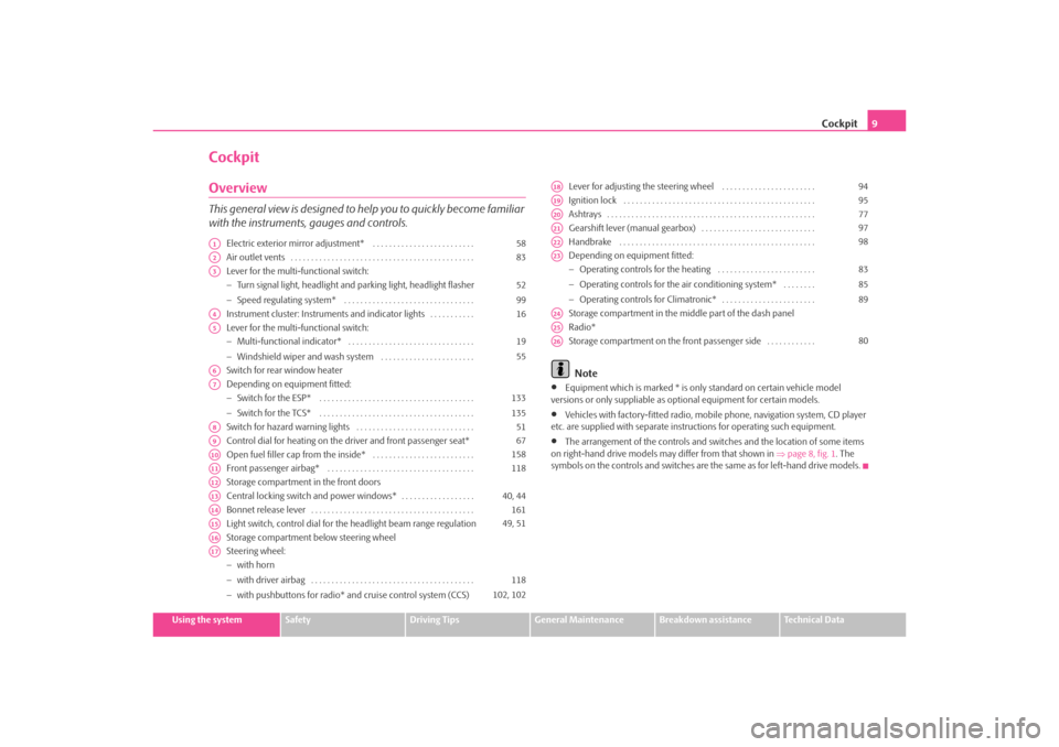
CockpitOverviewThis general view is designed to help you to quickly become familiar
with the instruments, gauges and controls.
Electric exterior mirror adjustment* . . . . . . . . . . . . . . . . . . . . . . . . .
Air outlet vents . . . . . . . . . . . . . . . . . . . . . . . . . . . . . . . . . . . . . . . . . . . . .
Lever for the multi-functional switch:
−Turn signal light, headlight and parking light, headlight flasher
− Speed regulating system* . . . . . . . . . . . . . . . . . . . . . . . . . . . . . . . .
Instrument cluster: Instrum ents and indicator lights . . . . . . . . . . .
Lever for the multi-functional switch:
− Multi-functional indicator* . . . . . . . . . . . . . . . . . . . . . . . . . . . . . . .
− Windshield wiper and wash system . . . . . . . . . . . . . . . . . . . . . . .
Switch for rear window heater
Depending on equipment fitted:
− Switch for the ESP* . . . . . . . . . . . . . . . . . . . . . . . . . . . . . . . . . . . . . .
− Switch for the TCS* . . . . . . . . . . . . . . . . . . . . . . . . . . . . . . . . . . . . . .
Switch for hazard warning lights . . . . . . . . . . . . . . . . . . . . . . . . . . . . .
Control dial for heating on the driver and front passenger seat*
Open fuel filler cap from the inside* . . . . . . . . . . . . . . . . . . . . . . . . .
Front passenger airbag* . . . . . . . . . . . . . . . . . . . . . . . . . . . . . . . . . . . .
Storage compartment in the front doors
Central locking switch and power windows* . . . . . . . . . . . . . . . . . .
Bonnet release lever . . . . . . . . . . . . . . . . . . . . . . . . . . . . . . . . . . . . . . . .
Light switch, control dial for the headlight beam range regulation
Storage compartment below steering wheel
Steering wheel:
− with horn
− with driver airbag . . . . . . . . . . . . . . . . . . . . . . . . . . . . . . . . . . . . . . . .
− with pushbuttons for radio* an d cruise control system (CCS) Lever for adjusting the steering wheel . . . . . . . . . . . . . . . . . . . . . . .
Ignition lock . . . . . . . . . . . . . . . . . . . . . . . . . . . . . . . . . . . . . . . . . . . . . . .
Ashtrays . . . . . . . . . . . . . . . . . . . . . . . . . . . . . . . . . . . . . . . . . . . . . . . . . . .
Gearshift lever (manual gearbox) . . . . . . . . . . . . . . . . . . . . . . . . . . . .
Handbrake . . . . . . . . . . . . . . . . . . . . . . . . . . . . . . . . . . . . . . . . . . . . . . . .
Depending on equipment fitted:
−
Operating controls for the heating . . . . . . . . . . . . . . . . . . . . . . . .
− Operating controls for the air conditioning system* . . . . . . . .
− Operating controls for Climatronic* . . . . . . . . . . . . . . . . . . . . . . .
Storage compartment in the middle part of the dash panel
Radio*
Storage compartment on the front passenger side . . . . . . . . . . . .
Note
•
Equipment which is marked * is only standard on certain vehicle model
versions or only suppliable as op tional equipment for certain models.
•
Vehicles with factory-fitted radio, mobile phone, navigation system, CD player
etc. are supplied with separate instru ctions for operating such equipment.
•
The arrangement of the controls and swit ches and the location of some items
on right-hand drive models may differ from that shown in ⇒page 8, fig. 1 . The
symbols on the controls and switches are the same as for left-hand drive models.
A1
58
A2
83
A3
52
99
A4
16
A5
19
55
A6A7
133
135
A8
51
A9
67
A10
158
A11
118
A12A13
40, 44
A14
161
A15
49, 51
A16A17
118
102, 102
A18
94
A19
95
A20
77
A21
97
A22
98
A23
83
85
89
A24A25A26
80
s2ig.book Page 9 Monday, November 10, 2008 11:20 AM
Page 20 of 226
Instruments and Indicator/Warning Lights19
Using the system
Safety
Driving Tips
General Maintenance
Breakdown assistance
Technical Data
The display disappears within 20 seconds after switching on the ignition. The trip
counter is also displayed af
ter pressing the reset button for the trip counter (for
more than 0,5 second).
Resetting Service Interval Display
It is only possible to reset the Service Interval Display, if a service message or at least
a pre-warning is shown on the display of the instrument cluster.
We recommend having this resetting performed by a specialist garage.
The specialist garage:
•
resets the memory of the display after the appropriate inspection,
•
makes an entry in the Service schedule,
•
affix the sticker with the entry of the following service interval to the side of the
dash panel on the driver's side.
Reset the service interval displays as follows by using the reset button
⇒ page 16, fig. 18 on the trip counter:
•
Press the reset button with the ignition switched off and and hold it down.
•
Switch the ignition on, release the reset button. The text Service or SERVICE
NOW appears in the display.
•
Turn the button for setting the clock to the right - as a result of this the display
is reset.Caution
We recommend that you do not reset the Service Interval Display yourself other-
wise this can result in the service interval display being incorrectly set, which may
also result in problems with operation of your vehicle.
Note
•
Never reset the display between service intervals otherwise this may result in
incorrect readouts.
•
information is retained in the Service Interval Display also after the battery of
the vehicle is disconnected.
•
it is necessary to re-code the Service Interval Display if a new instrument cluster
is installed during repair work. This work is carried out by a specialist garage.
•
The data displayed is the same after rese tting the display with flexible service
intervals (QG1) using the reset button as th at for a vehicle with fixed service inter-
vals (QG2). We therefore recommend having the Service Interval Display reset only
by a specialist garage which is familiar with the procedure for resetting the display
with a vehicle system tester.
•
Please refer to the brochure Service schedule for extensive information about
the service intervals.
Digital clockA clock-set button is installed on the bottom left beside the speedom-
eter for adjusting the clock ⇒page 16, fig. 18 .
Set hours
– Turn the reset button to the left.
Setting minutes
– Turn the reset button to the right.
WARNING
The clock should not be adjusted while driving for safety reasons but only
when the vehicle is stationary!Multi-functional indicator (onboard computer)*IntroductionThe multi-functional indicator appears in the display of the revolutions counter or
in the information display depending on the equipment fitted to your vehicle
⇒ page 23, fig. 23 .
A8
A7
s2ig.book Page 19 Monday, November 10, 2008 11:20 AM
Page 51 of 226
Lights and Visibility
50− It also concerns reverse light and turn signal lights.
− This mist has no influence on th e life of the lighting system.
Fog lights*
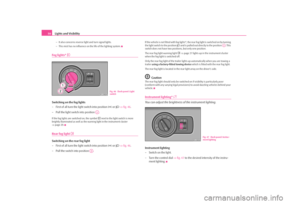
Switching on the fog lights
– First of all turn the light switch into position
or
⇒ fig. 46 .
– Pull the light switch into position .
If the fog lights are switched on, the symbol
next to the light switch is more
brightly illuminated as well as the warning light in the instrument cluster
⇒ page 29.
Rear fog light
Switching on the rear fog light
– First of all turn the light switch into position
or
⇒ fig. 46 .
– Pull the switch into position .
If the vehicle is not fitted with fog lights*, the rear fog light is switched on by turning
the light switch to the position
and is pulled out directly to the position . This
switch does not have two positions, but only one position.
The rear fog light warning light ⇒ page 27 lights up in the instrument cluster
when the fog light is switched off.
Only the rear fog light of the trailer ligh ts up automatically when you are towing a
trailer using a factory-fitted towing device which is fitted with the rear fog light.
The rear fog light is located in the rear light array on the driver's side.
Caution
The rear fog light should only be switched on if visibility is particularly poor
(conform with any varying legal provisions) to avoid dazzling vehicles behind your
vehicle.Instrument lighting*
You can adjust the brightness of the instrument lighting.Instrument lighting
– Switch on the light.
– Turn the control dial ⇒ fig. 47 to the desired intensity of the instru-
ment lighting.
Fig. 46 Dash panel: Light
switch
A1
A2
A2
Fig. 47 Dash panel: Instru-
ment lighting
s2ig.book Page 50 Monday, November 10, 2008 11:20 AM
Page 61 of 226
Seats and Storage
60Seats and StorageFront seatsBasic informationThe front seats have a wide range of different settings and can thus be matched to
the physical characteristics of the driver and front passenger. Correct adjustment of
the seats is particularly important for•
safely and quickly reaching the controls,
•
a relaxed, fatigue-free body position,
•
achieving the maximum protection of fered by the seat belts and the
airbag system.
WARNING
•
Never transport more occupants than the maximum seating in the
vehicle.
•
Each occupant must correctly fasten the seat belt belonging to the seat.
Children must be fastened ⇒page 125, “Transporting children safely” with
a suitable restraint system.
•
The front seats and the head restraints must always be adjusted to match
the body size of the seat occupant as well as the seat belts must always be
correctly fastened in order to provide an optimal protection for you and
your occupants.
•
Always keep your feet in the footwell when the car is being driven - never
place your feet on the instrument panel, out of the window or on the
surfaces of the seats. This is particularly important for the front seat
passenger. You will be exposed to increased risk of injury if it becomes
necessary to apply the brake or in the event of an accident. If an airbag is
deployed, you may suffer fatal injuries when adopting an incorrect seated
position!
•
It is important for the driver and front passenger to maintain a distance
of at least 25 cm from the steering wheel or dash panel. Not maintaining this minimum distance will mean that the airbag system will not be able to prop-
erly protect you - hazard! The front
seats and the head restraints must
always also be correctly adjusted to match the body size of the occupant.
•
Ensure that there are no objects in the footwell as any objects may get
behind the pedals during a driving or braking manoeuvre. You would then
no longer be able to operate the clutch, to brake or accelerate.
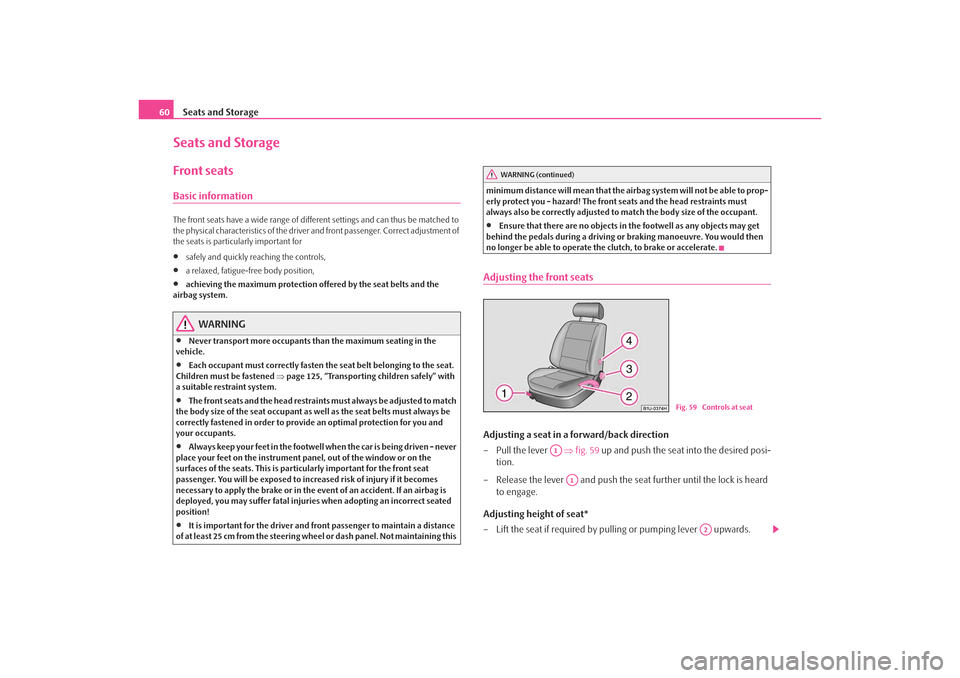
Adjusting the front seatsAdjusting a seat in a forward/back direction
– Pull the lever ⇒fig. 59 up and push the seat into the desired posi-
tion.
– Release the lever and push the seat further until the lock is heard to engage.
Adjusting height of seat*
– Lift the seat if required by pulling or pumping lever upwards.
WARNING (continued)
Fig. 59 Controls at seat
A1
A1
A2
s2ig.book Page 60 Monday, November 10, 2008 11:20 AM
Page 108 of 226

Passive Safety107
Using the system
Safety
Driving Tips
General Maintenance
Breakdown assistance
Technical Data
•
Adjust the backrest so that you are able to reach the highest point of the
steering wheel with your arms at a slight angle.
•
Adjust the head restraint so that the top edge of the head restraint is at the same
level as the upper part of your head ⇒page 106, fig. 114 .
•
Fasten the seat belt correctly ⇒page 112, “How are seat belts correctly
fastened?”.
Manual driver seat adjustment ⇒page 60, “Adjusting the front seats”.
Electrical driver seat adjustment ⇒page 61, “Adjusting front seats electrically*”.
WARNING
•
The front seats and the head restraints must always be adjusted to match
the body size of the seat occupant as well as the seat belts must always be
correctly fastened in order to provide an optimal protection for you and
your occupants.
•
The driver must maintain a distance of at least 25 cm to the steering
wheel ⇒page 106, fig. 113 . Not maintaining this minimum distance will
mean that the airbag system will not be able to properly protect you -
hazard!
•
When driving, hold the steering whee l with both hands firmly on the
outer edge in the 9 o'clock and 3 o'clock position. Never hold the steering
wheel firmly in the 12 o'clock position or in another way (e.g. in the middle
of the steering wheel or at the inner steering wheel edge). In such cases,
injuries to the arms, the hands and the head can occur when the driver
airbag is deployed.
•
The backrests must not be angled too far back when driving otherwise
this will affect proper operation of the seat belts and of the airbag system -
risk of injury!
•
Ensure that there are no objects in the footwell as any objects may get
behind the pedals during a driving or braking manoeuvre. You would then
no longer be able to operate the clutch, to brake or accelerate.
Correct seated position for the front passenger
The front passenger must maintain a distance of at least 25°cm from
the dash panel so that the combination of the airbag and the seat
belt offers the greatest possible safety when an airbag is deployed.For the safety of the front passenger and to reduce the risk of injury in the event of
an accident, we recommend the following setting:•
Adjust the front passenger seat as far as possible to the rear.
•
Adjust the head restraint so that the top edge of the head restraint is at the same
level as the upper part of your head ⇒page 106, fig. 114.
•
Fasten the seat belt correctly ⇒page 112, “How are seat belts correctly
fastened?”.
In exceptional cases the front passenger airbag can be deactivated ⇒page 122,
“Deactivating an airbag”.
Manual front passenger adjustment ⇒page 60, “Adjusting the front seats”.
Electrical front passenger seat adjustment ⇒page 61, “Adjusting front seats elec-
trically*”.
WARNING
•
The front seats and the head restraints must always be adjusted to match
the body size of the seat occupant as well as the seat belts must always be
correctly fastened in order to provide an optimal protection for you and
your occupants.
•
The front passenger must maintain a distance of at least 25 cm to the
dash panel. Not maintaining this mi nimum distance will mean that the
airbag system will not be able to properly protect you - hazard!
•
Always keep your feet in the footwell when the car is being driven - never
place your feet on the instrument panel, out of the window or on the
surfaces of the seats. You will be exposed to increased risk of injury if it
becomes necessary to apply the brake or in the event of an accident. If an
airbag is deployed, you may suffer fata l injuries when adopting an incorrect
seated position!
s2ig.book Page 107 Monday, November 10, 2008 11:20 AM
Page 197 of 226
Fuses and light bulbs
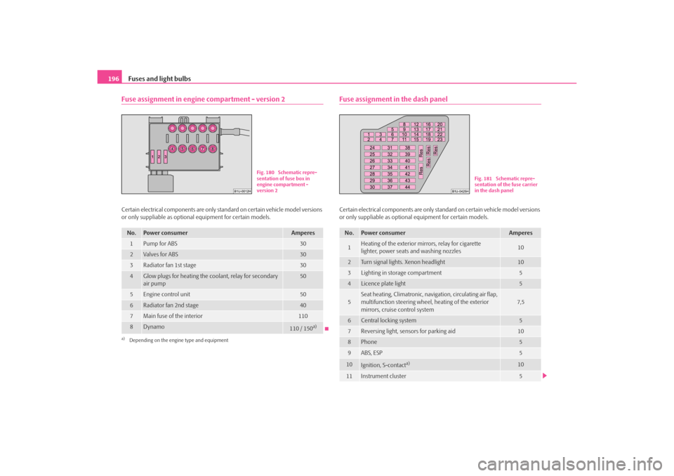
196Fuse assignment in engine compartment - version 2Certain electrical components are only st andard on certain vehicle model versions
or only suppliable as optional equipment for certain models.
Fuse assignment in the dash panelCertain electrical components are only standard on certain vehicle model versions
or only suppliable as optional equipment for certain models.
No.
Power consumer
Amperes
1
Pump for ABS
30
2
Valves for ABS
30
3
Radiator fan 1st stage
30
4
Glow plugs for heating the coolant, relay for secondary
air pump
50
5
Engine control unit
50
6
Radiator fan 2nd stage
40
7
Main fuse of the interior
110
8
Dynamo
110 / 150
a)
a)Depending on the engine type and equipment
Fig. 180 Schematic repre-
sentation of fuse box in
engine compartment -
version 2
No.
Power consumer
Amperes
1
Heating of the exterior mirrors, relay for cigarette
lighter, power seats and washing nozzles
10
2
Turn signal lights. Xenon headlight
10
3
Lighting in storage compartment
5
4
Licence plate light
5
5
Seat heating, Climatronic, navigation, circulating air flap,
multifunction steering wheel, heating of the exterior
mirrors, cruise control system
7,5
6
Central locking system
5
7
Reversing light, sensors for parking aid
10
8
Phone
5
9
ABS, ESP
5
10
Ignition, S-contact
a)
10
11
Instrument cluster
5
Fig. 181 Schematic repre-
sentation of the fuse carrier
in the dash panel
s2ig.book Page 196 Monday, November 10, 2008 11:20 AM