low beam SKODA OCTAVIA TOUR 2009 1.G / (1U) Owner's Manual
[x] Cancel search | Manufacturer: SKODA, Model Year: 2009, Model line: OCTAVIA TOUR, Model: SKODA OCTAVIA TOUR 2009 1.G / (1U)Pages: 226, PDF Size: 13.11 MB
Page 10 of 226
Cockpit9
Using the system
Safety
Driving Tips
General Maintenance
Breakdown assistance
Technical Data
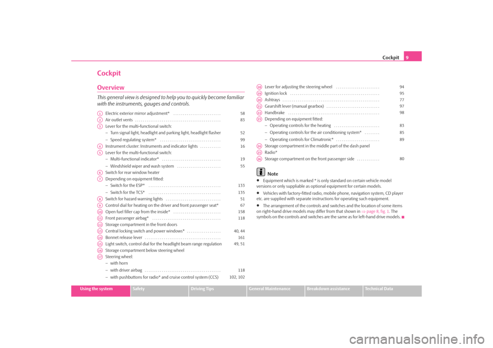
CockpitOverviewThis general view is designed to help you to quickly become familiar
with the instruments, gauges and controls.
Electric exterior mirror adjustment* . . . . . . . . . . . . . . . . . . . . . . . . .
Air outlet vents . . . . . . . . . . . . . . . . . . . . . . . . . . . . . . . . . . . . . . . . . . . . .
Lever for the multi-functional switch:
−Turn signal light, headlight and parking light, headlight flasher
− Speed regulating system* . . . . . . . . . . . . . . . . . . . . . . . . . . . . . . . .
Instrument cluster: Instrum ents and indicator lights . . . . . . . . . . .
Lever for the multi-functional switch:
− Multi-functional indicator* . . . . . . . . . . . . . . . . . . . . . . . . . . . . . . .
− Windshield wiper and wash system . . . . . . . . . . . . . . . . . . . . . . .
Switch for rear window heater
Depending on equipment fitted:
− Switch for the ESP* . . . . . . . . . . . . . . . . . . . . . . . . . . . . . . . . . . . . . .
− Switch for the TCS* . . . . . . . . . . . . . . . . . . . . . . . . . . . . . . . . . . . . . .
Switch for hazard warning lights . . . . . . . . . . . . . . . . . . . . . . . . . . . . .
Control dial for heating on the driver and front passenger seat*
Open fuel filler cap from the inside* . . . . . . . . . . . . . . . . . . . . . . . . .
Front passenger airbag* . . . . . . . . . . . . . . . . . . . . . . . . . . . . . . . . . . . .
Storage compartment in the front doors
Central locking switch and power windows* . . . . . . . . . . . . . . . . . .
Bonnet release lever . . . . . . . . . . . . . . . . . . . . . . . . . . . . . . . . . . . . . . . .
Light switch, control dial for the headlight beam range regulation
Storage compartment below steering wheel
Steering wheel:
− with horn
− with driver airbag . . . . . . . . . . . . . . . . . . . . . . . . . . . . . . . . . . . . . . . .
− with pushbuttons for radio* an d cruise control system (CCS) Lever for adjusting the steering wheel . . . . . . . . . . . . . . . . . . . . . . .
Ignition lock . . . . . . . . . . . . . . . . . . . . . . . . . . . . . . . . . . . . . . . . . . . . . . .
Ashtrays . . . . . . . . . . . . . . . . . . . . . . . . . . . . . . . . . . . . . . . . . . . . . . . . . . .
Gearshift lever (manual gearbox) . . . . . . . . . . . . . . . . . . . . . . . . . . . .
Handbrake . . . . . . . . . . . . . . . . . . . . . . . . . . . . . . . . . . . . . . . . . . . . . . . .
Depending on equipment fitted:
−
Operating controls for the heating . . . . . . . . . . . . . . . . . . . . . . . .
− Operating controls for the air conditioning system* . . . . . . . .
− Operating controls for Climatronic* . . . . . . . . . . . . . . . . . . . . . . .
Storage compartment in the middle part of the dash panel
Radio*
Storage compartment on the front passenger side . . . . . . . . . . . .
Note
•
Equipment which is marked * is only standard on certain vehicle model
versions or only suppliable as op tional equipment for certain models.
•
Vehicles with factory-fitted radio, mobile phone, navigation system, CD player
etc. are supplied with separate instru ctions for operating such equipment.
•
The arrangement of the controls and swit ches and the location of some items
on right-hand drive models may differ from that shown in ⇒page 8, fig. 1 . The
symbols on the controls and switches are the same as for left-hand drive models.
A1
58
A2
83
A3
52
99
A4
16
A5
19
55
A6A7
133
135
A8
51
A9
67
A10
158
A11
118
A12A13
40, 44
A14
161
A15
49, 51
A16A17
118
102, 102
A18
94
A19
95
A20
77
A21
97
A22
98
A23
83
85
89
A24A25A26
80
s2ig.book Page 9 Monday, November 10, 2008 11:20 AM
Page 13 of 226
The brief instruction
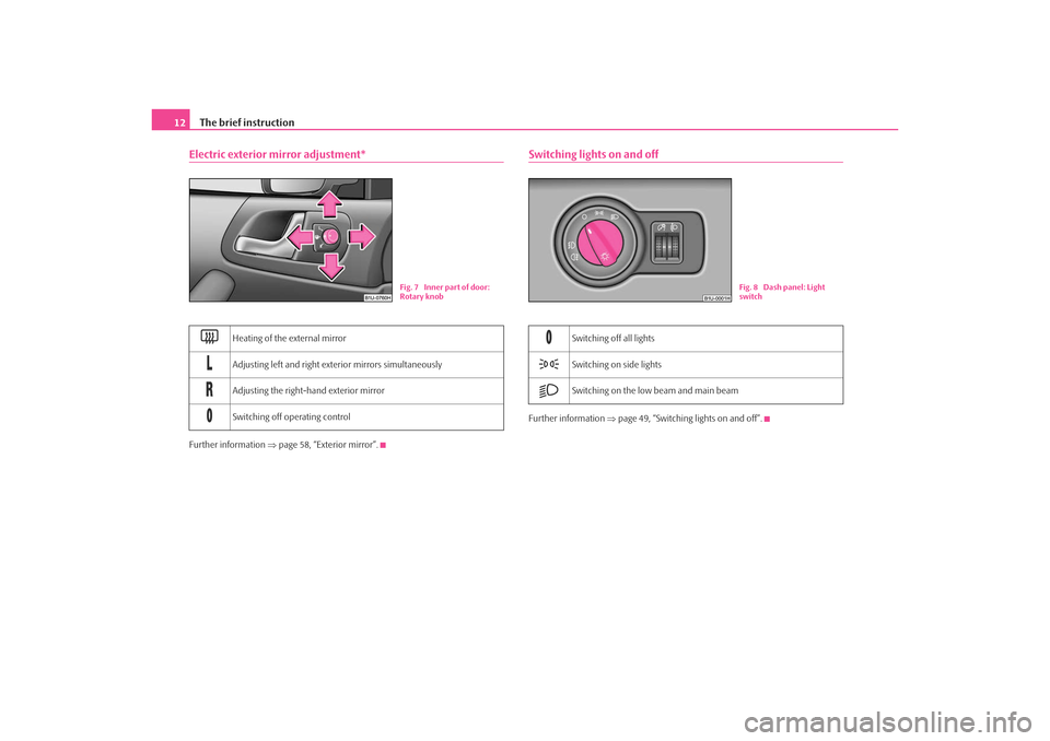
12Electric exterior mirror adjustment*Further information ⇒page 58, “Exterior mirror”.
Switching lights on and offFurther information ⇒page 49, “Switching lights on and off”.
Heating of the external mirror
Adjusting left and right exterior mirrors simultaneously
Adjusting the right-hand exterior mirror
Switching off operating control
Fig. 7 Inner part of door:
Rotary knob
Switching off all lights
Switching on side lights
Switching on the low beam and main beam
Fig. 8 Dash panel: Light
switch
s2ig.book Page 12 Monday, November 10, 2008 11:20 AM
Page 14 of 226
The brief instruction13
Using the system
Safety
Driving Tips
General Maintenance
Breakdown assistance
Technical Data
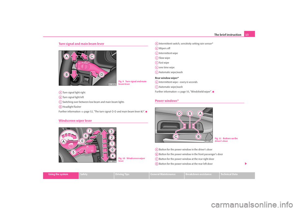
Turn signal and main beam lever Turn signal light right
Turn signal light left
Switching over between low beam and main beam lights
Headlight flasher
Further information ⇒page 52, “The turn signal and main beam lever ”.Windscreen wiper lever
Intermittent switch, sensitivity setting rain sensor*
Wipers off
Intermittent wipe
Slow wipe
Fast wipe
one time wipe
Automatic wipe/wash
Rear window wiper* Intermittent wipe - every 6 seconds
Automatic wipe/wash
Further information ⇒page 55, “Windshield wiper”.Power windows* Button for the power window in the driver's door
Button for the power window in the front passenger's door
Button for the power window at the rear right door
Button for the power window at the rear left door
Fig. 9 Turn signal and main
beam lever
AAABACAD
Fig. 10 Windscreen wiper
lever
AAA0A1A2A3A4A5A6A7
Fig. 11 Buttons on the
driver's door
AAABACAD
s2ig.book Page 13 Monday, November 10, 2008 11:20 AM
Page 28 of 226
Instruments and Indicator/Warning Lights27
Using the system
Safety
Driving Tips
General Maintenance
Breakdown assistance
Technical Data
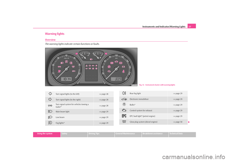
Warning lightsOverview
The warning lights indicate certain functions or faults.
Fig. 31 Instrument cluster with warning lights
Turn signal lights (to the left)
⇒page 28
Turn signal lights (to the right)
⇒page 28
Turn signal system fo r vehicles towing a
trailer*
⇒ page 28
Main beam light
⇒page 29
Low beam
⇒page 29
Fog lights*
⇒page 29
Rear fog light
⇒page 29
Electronic immobiliser
⇒page 29
Bulbs*
⇒page 29
Control system for exhaust
⇒page 29
EPC fault light* (petrol engine)
⇒page 29
Glow plug system (diesel engine)
⇒page 30
s2ig.book Page 27 Monday, November 10, 2008 11:20 AM
Page 30 of 226
Instruments and Indicator/Warning Lights29
Using the system
Safety
Driving Tips
General Maintenance
Breakdown assistance
Technical Data
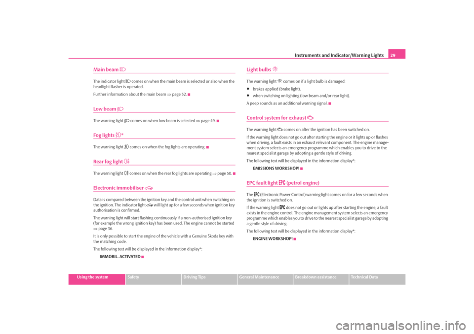
Main beam
The indicator light
comes on when the main beam is selected or also when the
headlight flasher is operated.
Further information about the main beam ⇒page 52.
Low beam
The warning light
comes on when low beam is selected ⇒page 49.
Fog lights
*
The warning light
comes on when the fog lights are operating.
Rear fog light
The warning light
comes on when the rear fog lights are operating ⇒page 50.
Electronic immobiliser
Data is compared between the ignition ke y and the control unit when switching on
the ignition. The indicator light
will light up for a few seconds when ignition key
authorisation is confirmed.
The warning light will start flashing conti nuously if a non-authorised ignition key
(for example the wrong ignition key) has been used. The engine cannot be started
⇒ page 36.
It is only possible to start the engine of the vehicle with a Genuine Škoda key with
the matching code.
The following text will be displayed in the information display*:
IMMOBIL. ACTIVATED
Light bulbs
The warning light
comes on if a light bulb is damaged:
•
brakes applied (brake light),
•
when switching on lighting (l ow beam and/or rear light).
A peep sounds as an additional warning signal.
Control system for exhaust
The warning light
comes on after the ignition has been switched on.
If the warning light does not go out after starting the engine or it lights up or flashes
when driving, a fault exists in an exhaus t relevant component. The engine manage-
ment system selects an emergency programme which enables you to drive to the
nearest specialist garage by adopting a gentle style of driving.
The following text will be displayed in the information display*:
EMISSIONS WORKSHOP!
EPC fault light
(petrol engine)
The
(Electronic Power Control) warning light comes on for a few seconds when
the ignition is switched on.
If the warning light
does not go out or lights up after starting the engine, a fault
exists in the engine control. The engine management system selects an emergency
programme which enables you to drive to the nearest specialist garage by adopting
a gentle style of driving.
The following text will be displayed in the information display*:
ENGINE WORKSHOP!
s2ig.book Page 29 Monday, November 10, 2008 11:20 AM
Page 50 of 226
Lights and Visibility49
Using the system
Safety
Driving Tips
General Maintenance
Breakdown assistance
Technical Data
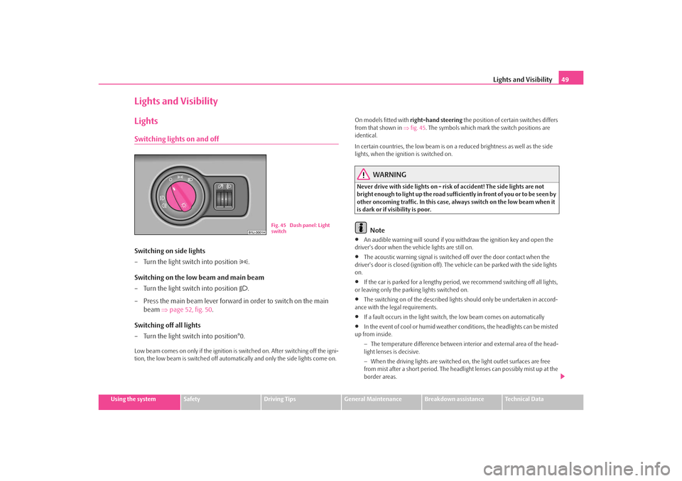
Lights and VisibilityLightsSwitching lights on and offSwitching on side lights
– Turn the light switch into position
.
Switching on the low beam and main beam
– Turn the light switch into position
.
– Press the main beam lever forward in order to switch on the main beam ⇒page 52, fig. 50 .
Switching off all lights
– Turn the light switch into position°0.
Low beam comes on only if the ignition is switched on. After switching off the igni-
tion, the low beam is switched off automatically and only the side lights come on. On models fitted with
right-hand steering the position of certain switches differs
from that shown in ⇒fig. 45 . The symbols which mark the switch positions are
identical.
In certain countries, the low beam is on a reduced brightness as well as the side
lights, when the ignition is switched on.
WARNING
Never drive with side lights on - risk of accident! The side lights are not
bright enough to light up the road suffic iently in front of you or to be seen by
other oncoming traffic. In this case, always switch on the low beam when it
is dark or if visibility is poor.
Note
•
An audible warning will sound if you wi thdraw the ignition key and open the
driver's door when the vehicle lights are still on.
•
The acoustic warning signal is switched off over the door contact when the
driver's door is closed (ignition off). The vehicle can be parked with the side lights
on.
•
If the car is parked for a lengthy period , we recommend switching off all lights,
or leaving only the parking lights switched on.
•
The switching on of the described lights should only be undertaken in accord-
ance with the legal requirements.
•
If a fault occurs in the light switch , the low beam comes on automatically
•
In the event of cool or humid weather co nditions, the headlights can be misted
up from inside.
−The temperature difference between interior and external area of the head-
light lenses is decisive.
− When the driving lights are switched on , the light outlet surfaces are free
from mist after a short period. The headlight lenses can possibly mist up at the
border areas.
Fig. 45 Dash panel: Light
switch
s2ig.book Page 49 Monday, November 10, 2008 11:20 AM
Page 52 of 226
Lights and Visibility51
Using the system
Safety
Driving Tips
General Maintenance
Breakdown assistance
Technical Data
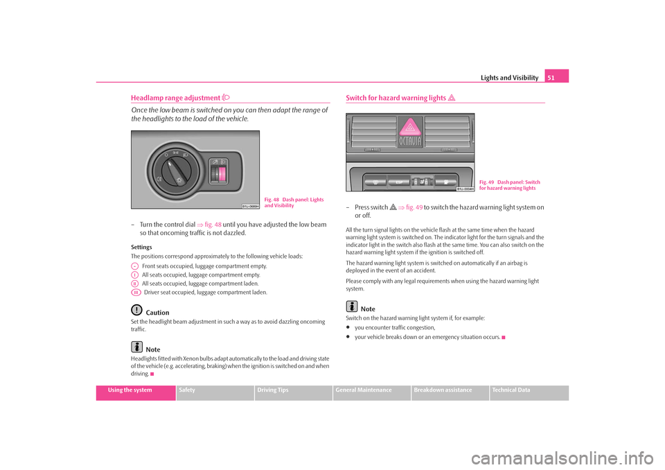
Headlamp range adjustment
Once the low beam is switched on you can then adapt the range of
the headlights to the load of the vehicle.– Turn the control dial ⇒fig. 48 until you have adjusted the low beam
so that oncoming traffic is not dazzled.Settings
The positions correspond approximat ely to the following vehicle loads:
Front seats occupied, luggage compartment empty.
All seats occupied, lugg age compartment empty.
All seats occupied, lugg age compartment laden.
Driver seat occupied, lu ggage compartment laden.
Caution
Set the headlight beam adjustment in such a way as to avoid dazzling oncoming
traffic.
Note
Headlights fitted with Xenon bulbs adapt au tomatically to the load and driving state
of the vehicle (e.g. accelerating, braking) when the ignition is switched on and when
driving.
Switch for hazard warning lights
–Press switch
⇒ fig. 49 to switc h the haz ard wa rning lig ht system on
or off.
All the turn signal lights on the vehicle flash at the same time when the hazard
warning light system is switched on. The indicator light for the turn signals and the
indicator light in the switch also flash at the same time. You can also switch on the
hazard warning light system if the ignition is switched off.
The hazard warning light system is switched on automatically if an airbag is
deployed in the event of an accident.
Please comply with any legal requirements when using the hazard warning light
system.
Note
Switch on the hazard warning light system if, for example:•
you encounter traffic congestion,
•
your vehicle breaks down or an emergency situation occurs.
Fig. 48 Dash panel: Lights
and Visibility
A-AIAIIAIII
Fig. 49 Dash panel: Switch
for hazard warning lights
s2ig.book Page 51 Monday, November 10, 2008 11:20 AM
Page 53 of 226
Lights and Visibility
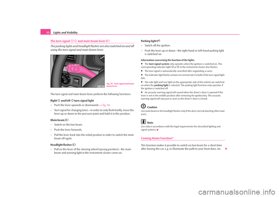
52The turn signal
and main beam lever
The parking lights and headlight flasher are also switched on and off
using the turn signal and main beam lever.The turn signal and main beam lever perform the following functions:
Right
and left
turn signal light
– Push the lever upwards or downwards ⇒fig. 50 .
– Turn signal for changing lanes - in or der to only flash briefly, move the
lever up or down to the pressure point and hold it in this position.
Main beam
– Switch on the low beam.
– Push the lever forwards.
– Pull the lever back into the initial position in order to switch the main beam off again.
Headlight flasher
– Pull on the lever of the steering wheel (sprung position) - the main
beam and warning light in the instrument cluster come on. Parking light
– Switch off the ignition.
– Push the lever up or down - the ri
ght-hand or left-hand parking light
is switched on.Information concerning the function of the lights.•
The turn signal system only operates when the ignition is switched on. The
corresponding indicator light
or in the instrument cluster also flashes.
•
The turn signal is automatically cancelled after negotiating a curve.
•
The indicator light flashes at twice its normal rate if a bulb of the turn signal light
fails.
•
The side light and rear light on the appr opriate side of the vehicle are switched
on when the parking light is selected. The parking light function only operates if
the ignition is switched off.
•
An acoustic warning signal will sound when the driver's door is opened if the
lever is not in the middle position after removing the ignition key. The acoustic
warning signal will stop just as s oon as the driver's door is closed.Caution
Use main beam or the headlight flasher only if this does not risk dazzling other road
users.
Note
Use only in accordance with the legal requirements the described lighting and
signal systems.Coming Home Function*This function makes it possible to sw itch on low beam for a short time
after leaving the car, e.g. to illumina te the path to your front door, etc.
Fig. 50 Turn signal and main
beam lever
s2ig.book Page 52 Monday, November 10, 2008 11:20 AM
Page 57 of 226
Lights and Visibility
56
Fast wipe
– Position the lever up into position .
Automatic wipe/wash for windscreen
– Pull the lever towards the steering wheel into the spring-tensioned position , the windscreen wiper and wash system will operate
immediately.
– Release the lever. The windscreen wash system stops and the wiper continues for another 1 - 3 wiper stro kes (depending on the period of
spraying of the windscreen).
Rain sensor*
– Move the lever into position .
– You can set the sensitivity of the sensor individually with switch .
– After switching off the ignition, you must then once again activate the
sensor by moving the lever into position , and then back into posi-
tion .
Wiping the rear window pane*
– Push the lever away from the steering wheel into position - the widescreen wiper will operate every 6 seconds.
Automatic wipe/wash for the rear window pane*
– Push the lever away from the steering wheel into the spring-tensioned position , the windscreen wiper and wash system will operate. As
long as you hold the lever in this position, the wiper and the wash
system operate - spring -tensioned position.
– Letting go of the lever will cause the windscreen wash system to stop and the wiper to continue for anot her 1 - 3 wiper strokes (depending
on the period of spraying of the windscreen). The lever will stay in
position after releasing it . Switching windscreen wipers off
– Move the lever back into its home position .
The windscreen wipers and the windscreen washer system only operate if the igni-
tion is switched on.
The rain sensor* automatically regulates
the break between the individual wiper
strokes depending on the intensity of the rain.
The windscreen washer nozzles are heated* when the ignition is switched on.
Top up with wash liquid ⇒page 174.
WARNING
•
Properly maintained windscreen wi per blades are essential for clear
visibility and safe driving ⇒page 57, “Replacing wiper blades for the wind-
screen wipers”.
•
Do not use the windscreen washer system at low temperatures, without
heating the windscreen beforehand. Otherwise the window cleaner could
freeze on the windscreen and re strict the view to the front.
•
The rain sensor only operates as a support. The driver is not released
from the responsibility to set the function of the windscreen wipers manu-
ally depending on the visibility conditions.Caution
In frosty weather, please first of all check whether the windscreen wiper blades are
not frozen to the windscreen before switching them on. Switching on windscreen
wipers when the blades are frozen to the windscreen may result in damage both to
the blades and the motor of the windscreen wipers!Headlight cleaning system*After each wash cycle of the windscreen an d if the parking lights, low beam light or
main beam light are switched on, the headlights are also cleaned.
A3
A5
A1
AA
A0
A1
A6
A7
A6
A0
s2ig.book Page 56 Monday, November 10, 2008 11:20 AM
Page 96 of 226
Starting-off and Driving95
Using the system
Safety
Driving Tips
General Maintenance
Breakdown assistance
Technical Data
Ignition lockPetrol engines
- ignition switched off, engine off, the steering can be locked.
- ignition switched on
- start engine
Diesel engines - interruption of fuel supply, ignition switched off, engine off, the steering can
be locked.
- heating glow plugs on, ignition switched on•
You should not switch on any major elec trical components during the heating
period otherwise the vehicle batter y will be drained unnecessarily.
- start engine
Applies to all models:
Position
To lock the steering , with the ignition key withdrawn, turn the steering wheel until
the steering locking pin is heard to engage. You should always lock the steering as
a general rule if you leave your vehicle. This acts as a deterrent against possible theft
of your vehicle ⇒.
Position Move the steering wheel back and forward a little if the ignition key cannot, or
cannot easily be turned into
this position, in order to release the steering lock.
Position
The engine is started in this position. At the same time switched on low beam or
main beam or other electrical compon ents with major power consumption are
briefly switched off. The ignition key moves back into position when one
releases the key.
The ignition key must be turned back into position each time before starting the
engine again. The starter repeat lock in th e ignition lock prevents the starter being
engaged when the engine is running and thus getting damaged.
WARNING
•
When driving, the ignition key must always be in the position (igni-
tion switched on) without the engine running. This position is indicated by
the warning lights coming on. If this is not the case, it could result in unex-
pected locking of the steering wheel - risk of accident!
•
Do not withdraw the ignition key from the lock until the car has come to
a stop. The steering lock can engage immediately - risk of accident!
•
Always withdraw the ignition key if you are going to leave the vehicle,
even for a short time. This is particularly important if children are left in the
vehicle. The children might otherwise star t the engine or switch on electrical
equipment (e.g. power windows) - risk of accident or injury!
Starting the engineGeneral
You can only start the engine only using an original ignition key.•
Place the gearshift lever into neutral and put on the handbrake firmly before
starting the engine.
•
The clutch pedal should be fully depressed when starting the engine which
means that the starter only has to crank the engine.
Fig. 105 Ignition lock posi-
tions
A1A2A3A1A2A3
A1A2
A3
A2
A1
A2
s2ig.book Page 95 Monday, November 10, 2008 11:20 AM