heater SKODA OCTAVIA TOUR 2009 1.G / (1U) Owner's Manual
[x] Cancel search | Manufacturer: SKODA, Model Year: 2009, Model line: OCTAVIA TOUR, Model: SKODA OCTAVIA TOUR 2009 1.G / (1U)Pages: 224, PDF Size: 13.53 MB
Page 10 of 224
Cockpit
9
Using the system
Safety
Driving Tips
General Maintenance
Breakdown assistance
Technical Data
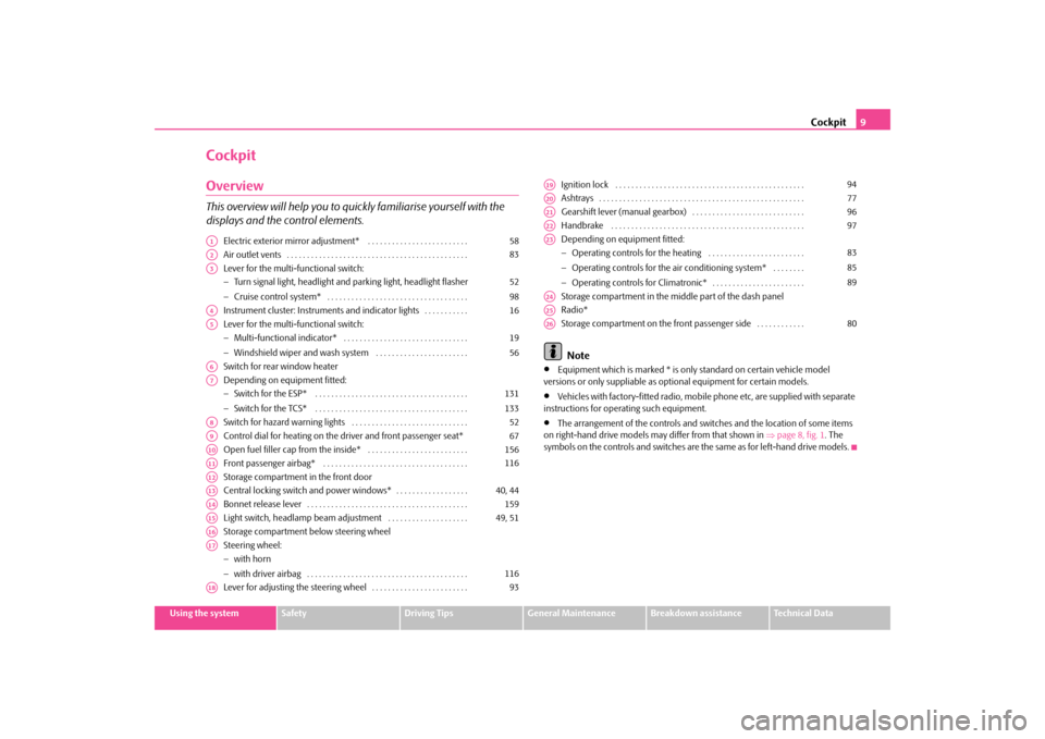
CockpitOverviewThis overview will help you to quickly familiarise yourself with the displays and the control elements.
Electric exterior mirror adjustment* . . . . . . . . . . . . . . . . . . . . . . . . . Air outlet vents . . . . . . . . . . . . . . . . . . . . . . . . . . . . . . . . . . . . . . . . . . . . . Lever for the multi-functional switch: − Turn signal light, headlight and parking light, headlight flasher − Cruise control system* . . . . . . . . . . . . . . . . . . . . . . . . . . . . . . . . . . . Instrument cluster: Instrum
ents and indicator lights . . . . . . . . . . .
Lever for the multi-functional switch: − Multi-functional indicator* . . . . . . . . . . . . . . . . . . . . . . . . . . . . . . . − Windshield wiper and wash system . . . . . . . . . . . . . . . . . . . . . . . Switch for rear window heater Depending on equipment fitted: − Switch for the ESP* . . . . . . . . . . . . . . . . . . . . . . . . . . . . . . . . . . . . . . − Switch for the TCS* . . . . . . . . . . . . . . . . . . . . . . . . . . . . . . . . . . . . . . Switch for hazard warning lights . . . . . . . . . . . . . . . . . . . . . . . . . . . . . Control dial for heating on the driver and front passenger seat* Open fuel filler cap from the inside* . . . . . . . . . . . . . . . . . . . . . . . . . Front passenger airbag* . . . . . . . . . . . . . . . . . . . . . . . . . . . . . . . . . . . . Storage compartment in the front door Central locking switch and power windows* . . . . . . . . . . . . . . . . . . Bonnet release lever . . . . . . . . . . . . . . . . . . . . . . . . . . . . . . . . . . . . . . . . Light switch, headlamp beam adjustment . . . . . . . . . . . . . . . . . . . . Storage compartment below steering wheelSteering wheel: − with horn − with driver airbag . . . . . . . . . . . . . . . . . . . . . . . . . . . . . . . . . . . . . . . . Lever for adjusting the steering wheel . . . . . . . . . . . . . . . . . . . . . . . .
Ignition lock . . . . . . . . . . . . . . . . . . . . . . . . . . . . . . . . . . . . . . . . . . . . . . . Ashtrays . . . . . . . . . . . . . . . . . . . . . . . . . . . . . . . . . . . . . . . . . . . . . . . . . . . Gearshift lever (manual gearbox) . . . . . . . . . . . . . . . . . . . . . . . . . . . . Handbrake . . . . . . . . . . . . . . . . . . . . . . . . . . . . . . . . . . . . . . . . . . . . . . . . Depending on equipment fitted: − Operating controls for the heating . . . . . . . . . . . . . . . . . . . . . . . . − Operating controls for the air conditioning system* . . . . . . . . − Operating controls for Climatronic* . . . . . . . . . . . . . . . . . . . . . . . Storage compartment in the midd
le part of the dash panel
Radio* Storage compartment on the front passenger side . . . . . . . . . . . . Note
•
Equipment which is marked * is only standard on certain vehicle model
versions or only suppliable as op
tional equipment for certain models.
•
Vehicles with factory-fitted radio, mobi
le phone etc, are supplied with separate
instructions for operating such equipment.•
The arrangement of the controls and swit
ches and the location of some items
on right-hand drive models may differ from that shown in
⇒page 8, fig. 1
. The
symbols on the controls and switches are the same as for left-hand drive models.
A1
58
A2
83
A3
52 98
A4
16
A5
1956
A6A7
131133
A8
52
A9
67
A10
156
A11
116
A12A13
40, 44
A14
159
A15
49, 51
A16A17
116
A18
93
A19
94
A20
77
A21
96
A22
97
A23
838589
A24A25A26
80
s2g8.b.book Page 9 Tuesday, April 7, 2009 8:53 AM
Page 56 of 224
Lights and Visibility
55
Using the system
Safety
Driving Tips
General Maintenance
Breakdown assistance
Technical Data
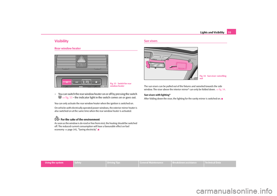
VisibilityRear window heater– You can switch the rear window heater on or off by pressing the switch
⇒
fig. 53
- the indicator light in the
switch comes on or goes out.
You can only activate the rear window he
ater when the ignition is switched on.
On vehicles with electrically operated power windows, the exterior mirror heater is also switched on at the same time when
the rear window heater is activated.
For the sake of the environment
As soon as the window is de-iced or free from mist, the heating should be switched off. The reduced current consumption will have a favourable effect on fuel economy
⇒page 141, “Saving electricity”.
Sun visorsThe sun visors can be pulled out of the fixtures and swiveled towards the side window. The visor above the interior mirror* can only be folded down.
⇒fig. 54
.
Sun visors with lighting* After folding down the visor, the lighting for the vanity mirror is switched on.
Fig. 53 Switch for rear window heater
Fig. 54 Sun visor: swivelling out
s2g8.b.book Page 55 Tuesday, April 7, 2009 8:53 AM
Page 60 of 224
Lights and Visibility
59
Using the system
Safety
Driving Tips
General Maintenance
Breakdown assistance
Technical Data
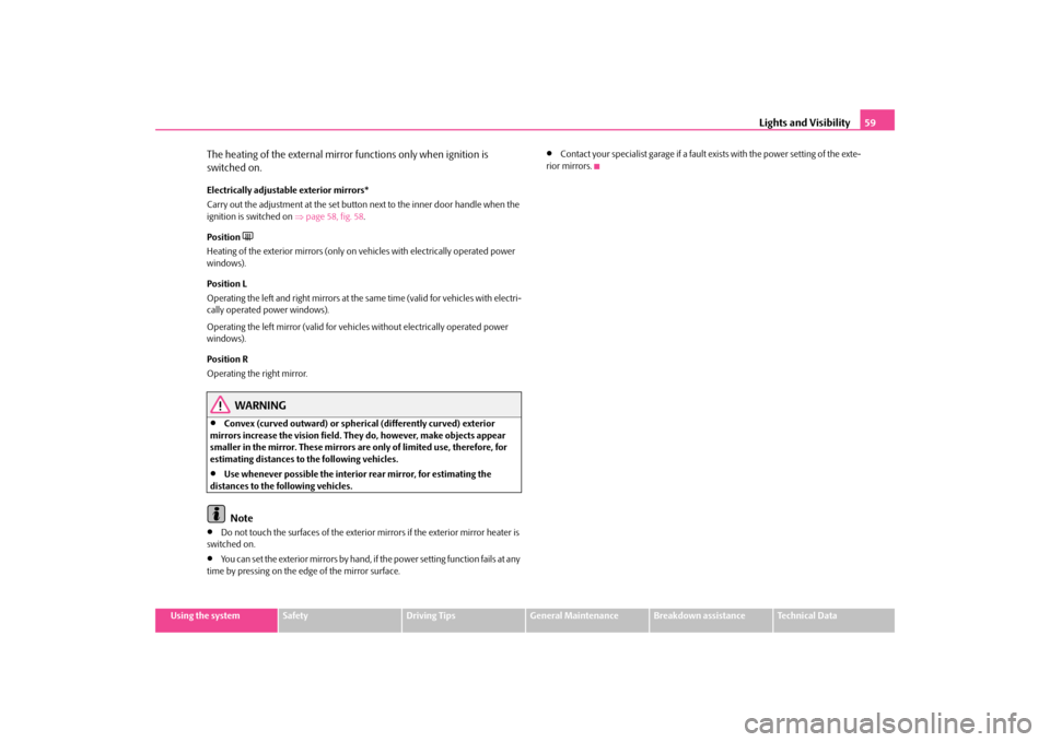
The heating of the external mirror functions only when ignition is switched on.Electrically adjustable exterior mirrors* Carry out the adjustment at the set button
next to the inner door handle when the
ignition is switched on
⇒page 58, fig. 58
.
Position
Heating of the exterior mirrors (only on vehicles with electrically operated power windows). Position L Operating the left and right mirrors at the same time (valid for vehicles with electri- cally operated power windows). Operating the left mirror (valid for vehicles without electrically operated power windows). Position R Operating the right mirror.
WARNING
•
Convex (curved outward) or spherical (differently curved) exterior
mirrors increase the vision field. They do, however, make objects appear smaller in the mirror. These mirrors are only of limited use, therefore, for estimating distances to the following vehicles.•
Use whenever possible the interior rear mirror, for estimating the
distances to the following vehicles.
Note
•
Do not touch the surfaces of the exterior mirrors if the exterior mirror heater is
switched on.•
You can set the exterior mirrors by hand, if
the power setting function fails at any
time by pressing on the edge of the mirror surface.
•
Contact your specialist garage if a fault exists with the power setting of the exte-
rior mirrors.
s2g8.b.book Page 59 Tuesday, April 7, 2009 8:53 AM
Page 68 of 224
Seats and Storage
67
Using the system
Safety
Driving Tips
General Maintenance
Breakdown assistance
Technical Data
Seat heating of the front seats*You can electrically heat the seat cu
shions and the seat backrests of the
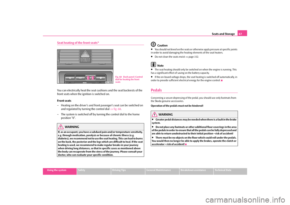
front seats when the ignition is switched on. Front seats – Heating on the driver's and front pasenger's seat can be switched on
and regulated by turning the control dial
⇒
fig. 68
.
– The system is switched off by turning the control dial to the home
position “0”.
WARNING
If, as an occupant, you have a subdued pain and/or temperature sensitivity, e.g. through medication, paralysis or because of chronic illness (e.g. diabetes), we recommend no
t to use the seat heating.
This can lead to burns
on the back, the posterior an
d the legs which are difficult to heal. If the seat
heating is used, we recommend to make regular breaks in your journey when driving long distances, so that in specific cases as mentioned above the body can recuperate from the stress of the journey. Please consult your doctor, who can evaluate your specific condition.
Caution
•
You should not kneel on the seats or othe
rwise apply pressure at specific points
in order to avoid damaging the heating elements of the seat heaters.•
Do not clean the seats moist
⇒page 152.
Note
•
The seat heating should only be switched
on when the engine is running. This
has a significant effect of sa
ving on the battery capacity.
•
If the on-board voltage drops, the seat heating is switched off automatically, in
order to provide sufficient electrical energy for the engine control.PedalsConcerning a secure depressing of the pe
dal, you should use only footmats from
the Škoda genuine accessories. Operation of the pedals must not be hindered!
WARNING
•
Greater pedal distances may be needed when there is a fault in the brake
system.•
Do not place any footmats or other additional floor coverings in the area
of the pedals in order to ensure that
all the pedals can be
fully depressed and
are able to return unobstructed to their initial position - risk of accident!•
There must be no objects on the floor which could roll under the pedals.
You would then no longer be able to
apply the brakes, oper
ate the clutch or
accelerator - risk of accident!
Fig. 68 Dash panel: Control dial for heating the front seats
s2g8.b.book Page 67 Tuesday, April 7, 2009 8:53 AM
Page 69 of 224
Seats and Storage
68
luggage compartmentLoading the luggage compartmentPlease observe the following in the inte
rest of having good handling char-
acteristics of your vehicle: – Distribute the items of luggage as evenly as possible.– Place heavy objects as far forward as possible. – Attach the items of luggage to the lashing eyes or the fixing net*
⇒
page 68.
In the event of an accident, there is such a
high kinetic energy wh
ich is produced by
small and light objects that they can caus
e severe injuries. The magnitude of the
kinetic energy depends on the speed at wh
ich the vehicle is travelling and on the
weight of the object. The speed at which the
vehicle is travelling is in this case the
more significant factor. Example: In the event of a frontal collision at a speed of 50 km/h, an unsecured object with a weight of 4.5 kg produces
an energy, which corresponds to 20 times
its own weight. This means that it results in a weight of approx. 90 kg. You can imagine the injuries that can occur, if th
is “bullet” is flying
through the interior
compartment and hits an occupant.
WARNING
•
Store the objects in the luggage comp
artment and attach them to the
lashing eyes.•
Loose objects in the passenger compartment can be thrown forward
during a sudden manoeuvre or in case of an accident and can injure the occupants or other oncoming traffic. This risk is still increased, if the objects which are flying around are hit by a depl
oyed airbag. In this case, the objects
which are thrown back can injure the occupants - hazard.•
Please note that the handling properti
es of your vehicle may be affected
when transporting heavy objects as a result of the displacement of the
centre of gravity. The speed and style
of driving must be adjusted accord-
ingly.•
The items carried in the luggage compar
tment should be stored in such
a way that no objects are able to slip forward if there are any sudden driving or braking manoeuvres undertaken - risk of injury!•
Never drive with the boot lid fully opened or slightly ajar otherwise
exhaust gases may get into the interior
of the vehicle - risk of poisoning!
•
On no account exceed the permissi
ble axle loads and the permissible
gross weight of the vehicle - risk of accident!•
Never transport occupants
in the luggage compartment!
Caution
Please ensure that the heating elements of the rear window heater are not damaged as a result of objects sliding in this area.
Note
Tyre pressure must be adjusted to the load
⇒page 173, fig. 159
.
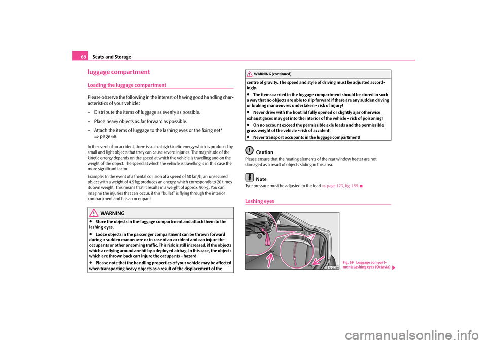
Lashing eyes
WARNING (continued)
Fig. 69 Luggage compart- ment: Lashing eyes (Octavia)
s2g8.b.book Page 68 Tuesday, April 7, 2009 8:53 AM
Page 72 of 224
Seats and Storage
71
Using the system
Safety
Driving Tips
General Maintenance
Breakdown assistance
Technical Data
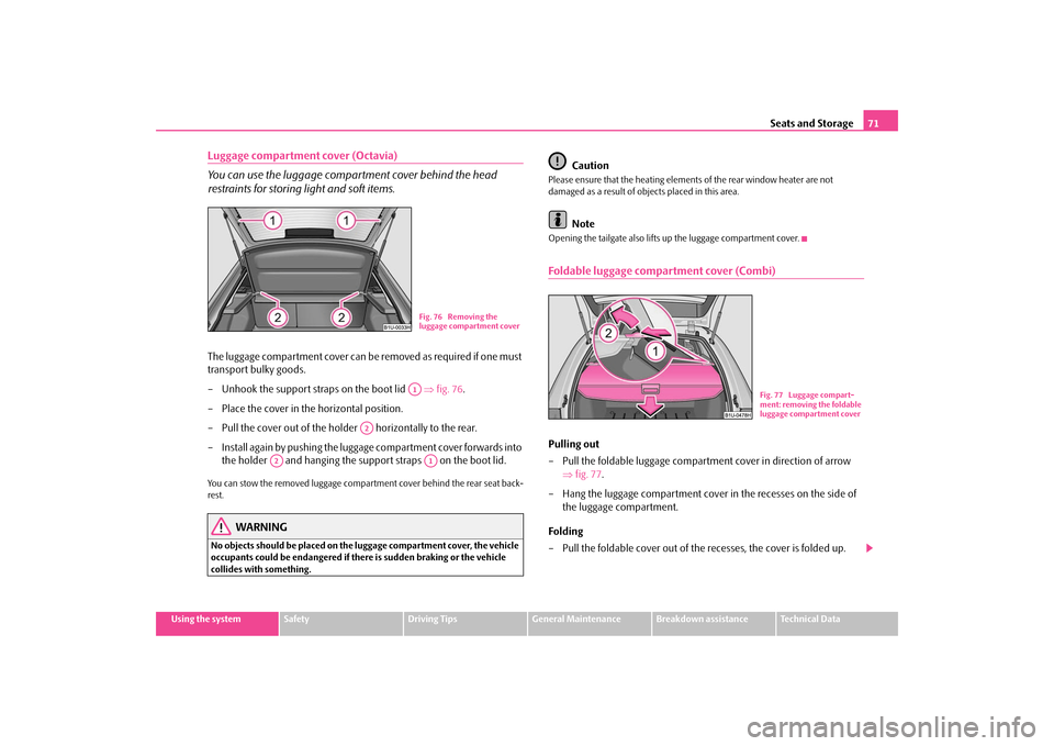
Luggage compartment cover (Octavia) You can use the luggage compartment cover behind the head restraints for storing
light and soft items.
The luggage compartment cover can be
removed as required if one must
transport bulky goods. – Unhook the support stra
ps on the boot lid
⇒
fig. 76
.
– Place the cover in the horizontal position. – Pull the cover out of the holder horizontally to the rear.– Install again by pushing the luggage
compartment cover forwards into
the holder and hanging the suppo
rt straps on the boot lid.
You can stow the removed luggage compartment cover behind the rear seat back- rest.
WARNING
No objects should be placed on the
luggage compartment cover, the vehicle
occupants could be endangered if th
ere is sudden braking or the vehicle
collides with something.
Caution
Please ensure that the heating elements of the rear window heater are not damaged as a result of obje
cts placed in this area.
Note
Opening the tailgate also lifts up the luggage compartment cover.Foldable luggage compartment cover (Combi)Pulling out – Pull the foldable luggage compartment cover in direction of arrow
⇒
fig. 77
.
– Hang the luggage compartment cover in the recesses on the side of
the luggage compartment.
Folding – Pull the foldable cover out of the recesses, the cover is folded up.
Fig. 76 Removing the luggage compartment coverA1
A2
A2
A1
Fig. 77 Luggage compart-ment: removing the foldable luggage compartment cover
s2g8.b.book Page 71 Tuesday, April 7, 2009 8:53 AM
Page 73 of 224
Seats and Storage
72
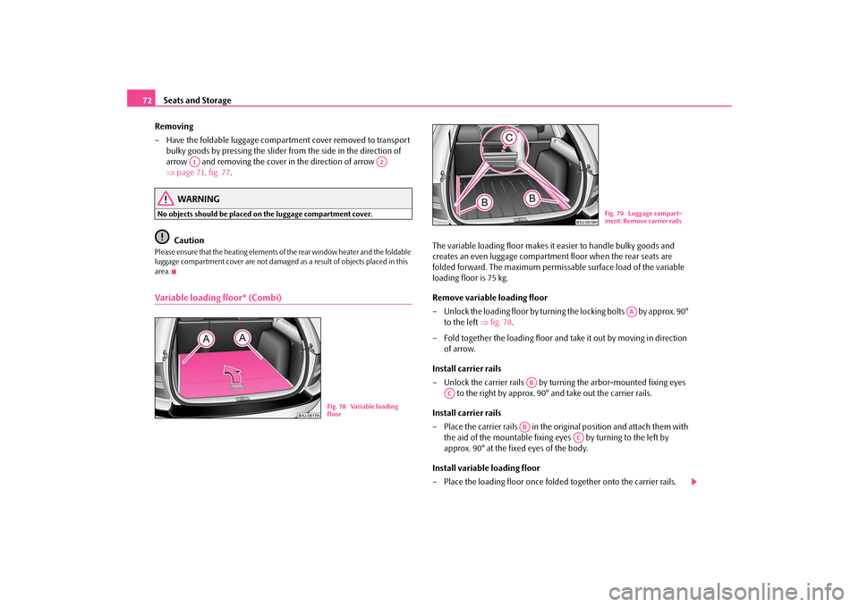
Removing – Have the foldable luggage compartment cover removed to transport
bulky goods by pressing the slider
from the side in the direction of
arrow and removing the cover in the direction of arrow ⇒
page 71, fig. 77
.
WARNING
No objects should be placed
on the luggage compartment cover.
Caution
Please ensure that the heating elements of the rear window heater and the foldable luggage compartment cover are not damaged as
a result of objects placed in this
area.Variable loading floor* (Combi)
The variable loading floor makes it
easier to handle bulky goods and
creates an even luggage compartmen
t floor when the rear seats are
folded forward. The maximum permissa
ble surface load of the variable
loading floor is 75 kg. Remove variable loading floor – Unlock the loading floor by turning the locking bolts by approx. 90°
to the left
⇒
fig. 78
.
– Fold together the loading floor and take it out by moving in direction
of arrow.
Install carrier rails – Unlock the carrier rails by turn
ing the arbor-mounted fixing eyes
to the right by approx. 90°
and take out the carrier rails.
Install carrier rails – Place the carrier rails in the original position and attach them with
the aid of the mountable fixing eyes by turning to the left by approx. 90° at the fixed eyes of the body.
Install variable loading floor – Place the loading floor once folded together onto the carrier rails.
A1
A2
Fig. 78 Variable loading floor
Fig. 79 Luggage compart-ment: Remove carrier rails
AA
AB
AC
AB
AC
s2g8.b.book Page 72 Tuesday, April 7, 2009 8:53 AM
Page 151 of 224
Taking care of your vehicle and cleaning the vehicle
150
Plastic partsExternal plastic parts are cleaned by norm
al washing. Plastic
parts and synthetic
leather can also be treated with
special solvent-free plastic cleaning agents
if a
damp cloth is not sufficient. Paint care pr
oducts are not suitable for plastic parts.
Caution
Solvent-free cleaners attack th
e material and can damage it.
WindowsOnly use a plastic ice scraper for removing snow and ice from the windows and mirrors. You should not move the ice scraper forward and backward but in one direction on the window which you are clea
ning in order to avoid any damage to
the surface of the glass. You can best remove residues of rubber,
oil, grease, wax or
silicone by using a
special window cleaner or a special silicone remover. You should also clean the windows regularly from the inside.Do not use window leathers
which you have used to polish the vehicle body to dry
off the windows. Residues of preservati
ves in the window leather can dirty the
window and reduce visibility. Do not affix any stickers over the inside of the rear window to avoid damage to the heating elements of the rear window heater
.
We recommend using a preservative from
Škoda genuine accessories offered by
your Škoda dealer.
Caution
Never remove snow or ice from the glass
parts with warm or hot water - risk of
formation of cracks in the glass!
The headlight lensesPlease do not use any aggressive cleaning
or chemical solvent products for cleaning
the front headlights - risk of damage to the plastic lenses.
Please use
soap and
clean warm water.
Caution
Never
wipe the headlights dry and do not
use any sharp objects for cleaning the
plastic lenses, this may result in damage
to the protective paintwork and conse-
quently in formation of cracks on the head
light lenses, e.g through effect of chem-
ical products.Door and window sealsThe rubber seals on the doors, boot lid,
bonnet and windows remain supple and
last longer if you treat them from time to
time with a rubber care product (e.g. with
a spray with silicone-free oil). You also avoid premature wear of the seals and prevent leakages in this way. It is also easier to open the doors. Rubber seals which are well cared for also do not stick together in cold winter weather.Locking cylinderWe recommend that you use the spray from Škoda original accessories with regreasing and anticorrosive effect
for de-icing lo
cking cylinders.
Note
When washing your vehicle, ensure that as
little water as possible gets into the
locking cylinders.
s2g8.b.book Page 150 Tuesday, April 7, 2009 8:53 AM
Page 195 of 224
Fuses and light bulbs
194
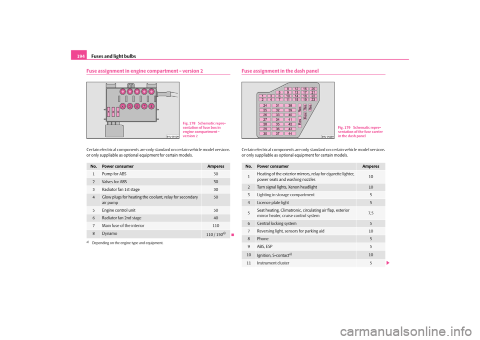
Fuse assignment in engine compartment - version 2Certain electrical components are only st
andard on certain vehicle model versions
or only suppliable as optional
equipment for certain models.
Fuse assignment in the dash panelCertain electrical components are only standard on certain vehicle model versions or only suppliable as optional
equipment for certain models.
No.
Power consumer
Amperes
1
Pump for ABS
30
2
Valves for ABS
30
3
Radiator fan 1st stage
30
4
Glow plugs for heating the coolant, relay for secondary air pump
50
5
Engine control unit
50
6
Radiator fan 2nd stage
40
7
Main fuse of the interior
110
8
Dynamo
110 / 150
a)
a)Depending on the engine type and equipment.
Fig. 178 Schematic repre- sentation of fuse box in engine compartment - version 2
No.
Power consumer
Amperes
1
Heating of the exterior mirrors, relay for cigarette lighter, power seats and washing nozzles
10
2
Turn signal lights, Xenon headlight
10
3
Lighting in storage compartment
5
4
Licence plate light
5
5
Seat heating, Climatronic, circulating air flap, exterior mirror heater, cruise control system
7,5
6
Central locking system
5
7
Reversing light, sensors for parking aid
10
8
Phone
5
9
ABS, ESP
5
10
Ignition, S-contact
a)
10
11
Instrument cluster
5
Fig. 179 Schematic repre- sentation of the fuse carrier in the dash panel
s2g8.b.book Page 194 Tuesday, April 7, 2009 8:53 AM
Page 196 of 224
Fuses and light bulbs
195
Using the system
Safety
Driving Tips
General Maintenance
Breakdown assistance
Technical Data
Electrically adjustable
seats are protected by
automatic circuit breakers
, which
switch on again automatically after a fe
w seconds after the overload has been
eliminated.BulbsChanging bulbsThe relevant lamp must always be switch
ed off before a light bulb is replaced.
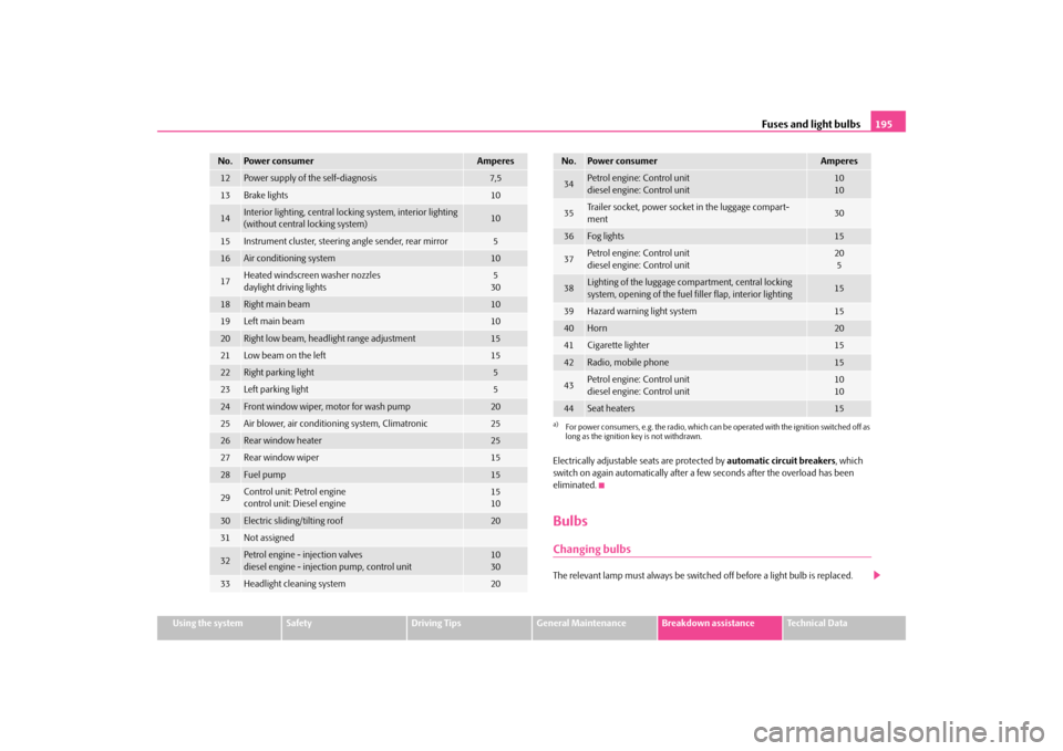
12
Power supply of the self-diagnosis
7,5
13
Brake lights
10
14
Interior lighting, central lockin
g system, interior lighting
(without central locking system)
10
15
Instrument cluster,
steering angle sender, rear mirror
5
16
Air conditioning system
10
17
Heated windscreen washer nozzles daylight driving lights
530
18
Right main beam
10
19
Left main beam
10
20
Right low beam, headlight range adjustment
15
21
Low beam on the left
15
22
Right parking light
5
23
Left parking light
5
24
Front window wiper, motor for wash pump
20
25
Air blower, air conditioning system, Climatronic
25
26
Rear window heater
25
27
Rear window wiper
15
28
Fuel pump
15
29
Control unit: Petrol engine control unit: Diesel engine
1510
30
Electric sliding/tilting roof
20
31
Not assigned
32
Petrol engine - injection valvesdiesel engine - injection pump, control unit
1030
33
Headlight cleaning system
20
No.
Power consumer
Amperes
34
Petrol engine: Control unitdiesel engine: Control unit
1010
35
Trailer socket, power socket in the luggage compart- ment
30
36
Fog lights
15
37
Petrol engine: Control unit diesel engine: Control unit
205
38
Lighting of the luggage compartment, central locking system, opening of the fuel filler flap, interior lighting
15
39
Hazard warning light system
15
40
Horn
20
41
Cigarette lighter
15
42
Radio, mobile phone
15
43
Petrol engine: Control unit diesel engine: Control unit
1010
44
Seat heaters
15
a)For power consumers, e.g. the radio, which can be
operated with the ignition switched off as
long as the ignition key is not withdrawn.No.
Power consumer
Amperes
s2g8.b.book Page 195 Tuesday, April 7, 2009 8:53 AM