airbag off SKODA OCTAVIA TOUR 2010 2.G / (1Z) Owner's Manual
[x] Cancel search | Manufacturer: SKODA, Model Year: 2010, Model line: OCTAVIA TOUR, Model: SKODA OCTAVIA TOUR 2010 2.G / (1Z)Pages: 199, PDF Size: 12.09 MB
Page 4 of 199
Contents3
Using the system
Safety
Driving Tips
General Maintenance
Breakdown assistance
Technical Data
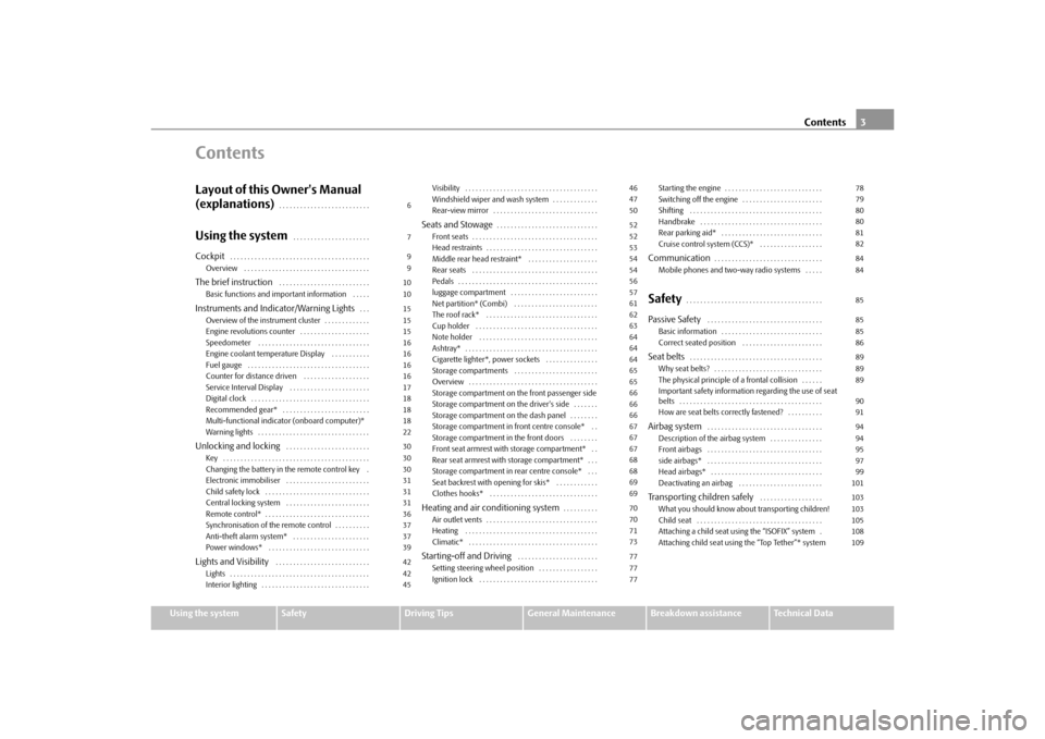
ContentsLayout of this Owner's Manual
(explanations)
. . . . . . . . . . . . . . . . . . . . . . . . . .
Using the system
. . . . . . . . . . . . . . . . . . . . . .
Cockpit
. . . . . . . . . . . . . . . . . . . . . . . . . . . . . . . . . . . . . . . .
Overview . . . . . . . . . . . . . . . . . . . . . . . . . . . . . . . . . . . .
The brief instruction
. . . . . . . . . . . . . . . . . . . . . . . . . .
Basic functions and important information . . . . .
Instruments and Indic ator/Warning Lights
. . .
Overview of the instrument cluster . . . . . . . . . . . . .
Engine revolutions counter . . . . . . . . . . . . . . . . . . . .
Speedometer . . . . . . . . . . . . . . . . . . . . . . . . . . . . . . . .
Engine coolant temperature Display . . . . . . . . . . .
Fuel gauge . . . . . . . . . . . . . . . . . . . . . . . . . . . . . . . . . . .
Counter for distance driven . . . . . . . . . . . . . . . . . . .
Service Interval Display . . . . . . . . . . . . . . . . . . . . . . .
Digital clock . . . . . . . . . . . . . . . . . . . . . . . . . . . . . . . . . .
Recommended gear* . . . . . . . . . . . . . . . . . . . . . . . . .
Multi-functional indicator (onboard computer)*
Warning lights . . . . . . . . . . . . . . . . . . . . . . . . . . . . . . . .
Unlocking and locking
. . . . . . . . . . . . . . . . . . . . . . . .
Key . . . . . . . . . . . . . . . . . . . . . . . . . . . . . . . . . . . . . . . . . .
Changing the battery in the remote control key .
Electronic immobiliser . . . . . . . . . . . . . . . . . . . . . . . .
Child safety lock . . . . . . . . . . . . . . . . . . . . . . . . . . . . . .
Central locking system . . . . . . . . . . . . . . . . . . . . . . . .
Remote control* . . . . . . . . . . . . . . . . . . . . . . . . . . . . . .
Synchronisation of the remote control . . . . . . . . . .
Anti-theft alarm system* . . . . . . . . . . . . . . . . . . . . . .
Power windows* . . . . . . . . . . . . . . . . . . . . . . . . . . . . .
Lights and Visibility
. . . . . . . . . . . . . . . . . . . . . . . . . . .
Lights . . . . . . . . . . . . . . . . . . . . . . . . . . . . . . . . . . . . . . . .
Interior lighting . . . . . . . . . . . . . . . . . . . . . . . . . . . . . . . Visibility . . . . . . . . . . . . . . . . . . . . . . . . . . . . . . . . . . . . . .
Windshield wiper and wash system . . . . . . . . . . . . .
Rear-view mirror . . . . . . . . . . . . . . . . . . . . . . . . . . . . . .
Seats and Stowage
. . . . . . . . . . . . . . . . . . . . . . . . . . . . .
Front seats . . . . . . . . . . . . . . . . . . . . . . . . . . . . . . . . . . . .
Head restraints . . . . . . . . . . . . . . . . . . . . . . . . . . . . . . . .
Middle rear head restraint* . . . . . . . . . . . . . . . . . . . .
Rear seats . . . . . . . . . . . . . . . . . . . . . . . . . . . . . . . . . . . .
Pedals . . . . . . . . . . . . . . . . . . . . . . . . . . . . . . . . . . . . . . . .
luggage compartment . . . . . . . . . . . . . . . . . . . . . . . . .
Net partition* (Combi) . . . . . . . . . . . . . . . . . . . . . . . .
The roof rack* . . . . . . . . . . . . . . . . . . . . . . . . . . . . . . . .
Cup holder . . . . . . . . . . . . . . . . . . . . . . . . . . . . . . . . . . .
Note holder . . . . . . . . . . . . . . . . . . . . . . . . . . . . . . . . . .
Ashtray* . . . . . . . . . . . . . . . . . . . . . . . . . . . . . . . . . . . . . .
Cigarette lighter*, power sockets . . . . . . . . . . . . . . .
Storage compartments . . . . . . . . . . . . . . . . . . . . . . . .
Overview . . . . . . . . . . . . . . . . . . . . . . . . . . . . . . . . . . . . .
Storage compartment on the front passenger side
Storage compartment on the driver's side . . . . . . .
Storage compartment on the dash panel . . . . . . . .
Storage compartment in front centre console* . .
Storage compartment in the front doors . . . . . . . .
Front seat armrest with storage compartment* . .
Rear seat armrest with storage compartment* . . .
Storage compartment in rear centre console* . . .
Seat backrest with opening for skis* . . . . . . . . . . . .
Clothes hooks* . . . . . . . . . . . . . . . . . . . . . . . . . . . . . . .
Heating and air conditioning system
. . . . . . . . . .
Air outlet vents . . . . . . . . . . . . . . . . . . . . . . . . . . . . . . . .
Heating . . . . . . . . . . . . . . . . . . . . . . . . . . . . . . . . . . . . . .
Climatic* . . . . . . . . . . . . . . . . . . . . . . . . . . . . . . . . . . . . .
Starting-off and Driving
. . . . . . . . . . . . . . . . . . . . . . .
Setting steering wheel position . . . . . . . . . . . . . . . . .
Ignition lock . . . . . . . . . . . . . . . . . . . . . . . . . . . . . . . . . . Starting the engine . . . . . . . . . . . . . . . . . . . . . . . . . . . .
Switching off the engine . . . . . . . . . . . . . . . . . . . . . . .
Shifting . . . . . . . . . . . . . . . . . . . . . . . . . . . . . . . . . . . . . .
Handbrake . . . . . . . . . . . . . . . . . . . . . . . . . . . . . . . . . . .
Rear parking aid* . . . . . . . . . . . . . . . . . . . . . . . . . . . . .
Cruise control system (CCS)* . . . . . . . . . . . . . . . . . .
Communication
. . . . . . . . . . . . . . . . . . . . . . . . . . . . . . .
Mobile phones and two-way radio systems . . . . .
Safety
. . . . . . . . . . . . . . . . . . . . . . . . . . . . . . . . . . . . . . .
Passive Safety
. . . . . . . . . . . . . . . . . . . . . . . . . . . . . . . . .
Basic information . . . . . . . . . . . . . . . . . . . . . . . . . . . . .
Correct seated position . . . . . . . . . . . . . . . . . . . . . . .
Seat belts
. . . . . . . . . . . . . . . . . . . . . . . . . . . . . . . . . . . . . .
Why seat belts? . . . . . . . . . . . . . . . . . . . . . . . . . . . . . . .
The physical principle of a frontal collision . . . . . .
Important safety information regarding the use of seat
belts . . . . . . . . . . . . . . . . . . . . . . . . . . . . . . . . . . . . . . . . .
How are seat belts correctly fastened? . . . . . . . . . .
Airbag system
. . . . . . . . . . . . . . . . . . . . . . . . . . . . . . . . .
Description of the airbag system . . . . . . . . . . . . . . .
Front airbags . . . . . . . . . . . . . . . . . . . . . . . . . . . . . . . . .
side airbags* . . . . . . . . . . . . . . . . . . . . . . . . . . . . . . . . .
Head airbags* . . . . . . . . . . . . . . . . . . . . . . . . . . . . . . . .
Deactivating an airbag . . . . . . . . . . . . . . . . . . . . . . . .
Transporting children safely
. . . . . . . . . . . . . . . . . .
What you should know about transporting children!
Child seat . . . . . . . . . . . . . . . . . . . . . . . . . . . . . . . . . . . .
Attaching a child seat using the “ISOFIX” system .
Attaching child seat using the “Top Tether”* system
6799101015151516161616171818182230303031313136373739424245
4647505252535454565761626364646465656666666767676868696970707173777777
78798080818284848585858689898990919494959799101103103105108109
s2bs.2.book Page 3 Monday, September 27, 2010 9:53 AM
Page 10 of 199
Cockpit9
Using the system
Safety
Driving Tips
General Maintenance
Breakdown assistance
Technical Data
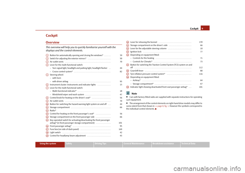
CockpitOverviewThis overview will help you to quic kly familiarise yourself with the
displays and the control elements.
Button for automatically opening and closing the windows* . . . . . . .
Switch for adjusting the exterior mirrors* . . . . . . . . . . . . . . . . . . . . . . . .
Air outlet vents . . . . . . . . . . . . . . . . . . . . . . . . . . . . . . . . . . . . . . . . . . . . . . . .
Lever for the multi-functional switch:
Turn signal light, headlight and parking light, headlight flasher . .
Cruise control system* . . . . . . . . . . . . . . . . . . . . . . . . . . . . . . . . . . . . . . .
Steering wheel:
with horn
with driver airbag . . . . . . . . . . . . . . . . . . . . . . . . . . . . . . . . . . . . . . . . . . .
Instrument cluster: Instruments and indicator lights . . . . . . . . . . . . . .
Lever for the multi-functional switch:
Multi-functional indicator* . . . . . . . . . . . . . . . . . . . . . . . . . . . . . . . . . . .
Windshield wiper and wash system . . . . . . . . . . . . . . . . . . . . . . . . . . .
Control knob for heating on the driver's seat* . . . . . . . . . . . . . . . . . . . .
Air outlet vents . . . . . . . . . . . . . . . . . . . . . . . . . . . . . . . . . . . . . . . . . . . . . . . .
Button for switching the hazard warning light system on and off . . .
Storage compartment . . . . . . . . . . . . . . . . . . . . . . . . . . . . . . . . . . . . . . . . . .
Radio*
Control for heating on the front passenger's seat* . . . . . . . . . . . . . . . .
Storage compartment on the front passenger side . . . . . . . . . . . . . . . .
Key-operated switch for activating/deactivating the front passenger
airbag* (in front passenger storage compartment) . . . . . . . . . . . . . . . .
Front passenger airbag* . . . . . . . . . . . . . . . . . . . . . . . . . . . . . . . . . . . . . . . .
Fuse box (on side of dash panel) . . . . . . . . . . . . . . . . . . . . . . . . . . . . . . . .
Light switch . . . . . . . . . . . . . . . . . . . . . . . . . . . . . . . . . . . . . . . . . . . . . . . . . . .
Control for headlamp beam adjustment . . . . . . . . . . . . . . . . . . . . . . . . . Lever for releasing the bonnet . . . . . . . . . . . . . . . . . . . . . . . . . . . . . . . . . . .
Storage compartment on the driver's side . . . . . . . . . . . . . . . . . . . . . . . .
Lever for the adjustable steering column . . . . . . . . . . . . . . . . . . . . . . . . .
Ignition lock . . . . . . . . . . . . . . . . . . . . . . . . . . . . . . . . . . . . . . . . . . . . . . . . . . .
Depending on equipment fitted:
Controls for the heating . . . . . . . . . . . . . . . . . . . . . . . . . . . . . . . . . . . . . .
Controls for Climatic* . . . . . . . . . . . . . . . . . . . . . . . . . . . . . . . . . . . . . . . .
Button for switching the Traction Control System (TCS) system on and
off . . . . . . . . . . . . . . . . . . . . . . . . . . . . . . . . . . . . . . . . . . . . . . . . . . . . . . . . . . . .
Gearshift lever . . . . . . . . . . . . . . . . . . . . . . . . . . . . . . . . . . . . . . . . . . . . . . . . .
Tyre inflation pressure-control system* . . . . . . . . . . . . . . . . . . . . . . . . . .
Depending on equipment fitted:
Ashtray* . . . . . . . . . . . . . . . . . . . . . . . . . . . . . . . . . . . . . . . . . . . . . . . . . . . .
Storage compartment* . . . . . . . . . . . . . . . . . . . . . . . . . . . . . . . . . . . . . . .
Indicator light showing deactivated front seat passenger airbag* . . .
Note
Cars with factory-fitted radio are supplied with separate instructions for operating
such equipment.
The arrangement of the control elements on right-hand drive models may differ to
some extent from that shown in page 8, fig. 1 . However the symbols correspond to
the individual control elements.
A1
39
A2
50
A3
70
A4
4482
A5
95
A6
15
A7
1847
A8
56
A9
70
A10
44
A11
66
A12A13
56
A14
66
A15
101
A16
95
A17
169
A18
42
A19
43
A20
139
A21
66
A22
10
A23
77
A24
7173
A25
112
A26
80
A27
116
A28
6467
A29
101
s2bs.2.book Page 9 Monday, September 27, 2010 9:53 AM
Page 25 of 199
Instruments and Indicator/Warning Lights
24
Further information about the main beam page 44.Low beam
The warning light
comes on when low beam is selected page 42.
Rear fog light
The warning light
comes on when the rear fog lights are operating page 43.
Cruise control system*
The warning light
lights up, when operating the speed regulating system.
Bulb failure
The warning light
comes on if a bulb is faulty:
up to 2 seconds after the ignition is switched on,
when switching on the defective light bulb.
The rear side lights and the licence plate li ghting require several light bulbs. The indi-
cator light
only lights up if all light bulbs of the licence plate lighting or the parking
light (in one rear light unit) are defective. Check regularly the function of the light
bulbs.
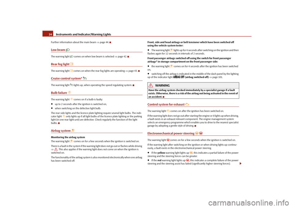
Airbag system
Monitoring the airbag system
The warning light
comes on for a few seconds when the ignition is switched on.
There is a fault in the system if the warning light does not go out or flashes while driving
. This also applies if the warning light does not come on when the ignition is
switched on.
The functionality of the airbag system is also monitored electronically when one airbag
has been switched off. Front, side and head airbags or belt tensioner which have been switched off
using the vehicle
system tester:
The warning light
lights up for 4 seconds after switching on the ignition and then
flashes again for 12 seconds in intervals of 2 seconds.
Front passenger airbags sw itched off using the switch for front passenger
airbags* in storage compartmen t on the front passenger side:
the warning light
comes on for 4 seconds after the ignition has been switched
on,
switching off the airbag is indicated in the middle of the dash panel by the lighting
up of the indicator light
(airbag switched off) page 101.
WARNING
Have the airbag system checked immediat ely by a specialist garage if a fault
exists. Otherwise, there is a risk of the airbag not being activated in the event of
an accident.Control system for exhaust
The warning light
comes on after the ignition has been switched on.
If the warning light does not go out after starti ng the engine or it lights up when driving,
a fault exists in an exhaust relevant co mponent. The engine management system
selects an emergency programme which enables you to drive to the nearest specialist
garage by adopting a ge ntle style of driving.
Electromechanical power steering
The warning light
comes on for a few seconds when the ignition is switched on.
If the warning light after switching on the ignition or when driving lights up continu-
ously, a fault exists in the electromechanical power steering.
If the yellow warning light lights up
, this indicates a partial failure of the power
steering and the steering forces can be greater.
If the red warning light lights up
, this indicates a complete failure of the power
steering and the steering assist has failed (significantly higher steering forces).
s2bs.2.book Page 24 Monday, September 27, 2010 9:53 AM
Page 35 of 199
Unlocking and locking
34
Unlocking all doors and the boot lid
– Press button page 33, fig. 25. The symbol
goes out in the button.
The following applies if you have locked your vehicle using the button :
It is not possible to open the doors or the boot lid from the outside (safety feature,
e.g. when stopping at traffic lights etc.).
You can unlock the doors individually from the inside and open them by pulling the
door opening lever.
As long as one door is opened
3), the vehicle cannot be locked in order to avoid
inadvertently locking the key in the vehicle.
In the event of an accident in which the airbags are deployed, the locked doors are
automatically unlocked from the inside in orde r to enable rescuers to gain access to
the vehicle.
By pressing and holding the button or , you can conveniently close or open the
windows page 41.
WARNING
The central locking system al so operates if the ignition is switched off. All the
doors and the boot lid are locked. Children should never be left unattended in
the vehicle since it is difficult to prov ide assistance from the outside when the
doors are locked. Locked doors make it difficult for rescuers to get into the
vehicle in an emergency - hazard!
Note
The door opening lever and the buttons for the central locking system do not operate
if the safe securing system is activated.
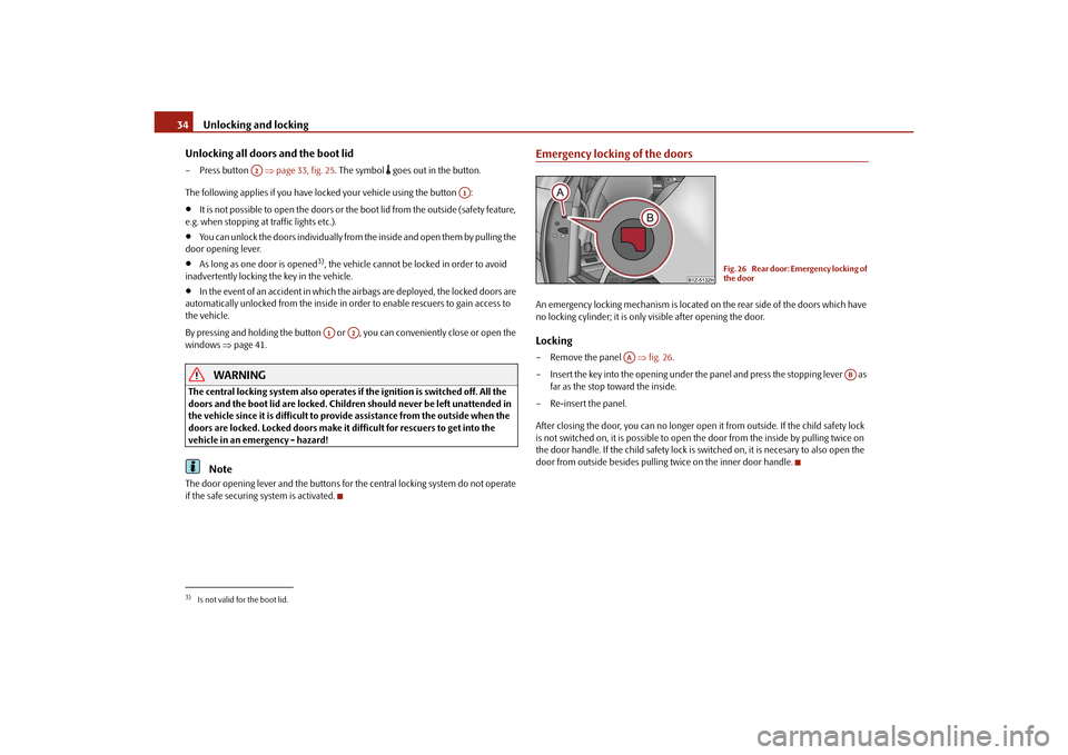
Emergency locking of the doorsAn emergency locking mechanism is located on the rear side of the doors which have
no locking cylinder; it is only visible after opening the door.Locking– Remove the panel fig. 26 .
– Insert the key into the opening under the panel and press the stopping lever as
far as the stop toward the inside.
– Re-insert the panel.
After closing the door, you can no longer open it from outside. If the child safety lock
is not switched on, it is possible to open the door from the inside by pulling twice on
the door handle. If the child sa fety lock is switched on, it is necesary to also open the
door from outside besides pulling twice on the inner door handle.
3)Is not valid for the boot lid.
A2
A1
A1
A2
Fig. 26 Rear door: Emergency locking of
the door
AA
AB
s2bs.2.book Page 34 Monday, September 27, 2010 9:53 AM
Page 45 of 199
Lights and Visibility
44
Settings
The positions correspond approximately to the following vehicle loads:
Front seats occupied, luggage compartment empty.
All seats occupied, luggage compartment empty.
All seats occupied, luggage compartment laden.
Driver seat occupied, lu ggage compartment laden.
Caution
Set the headlight beam adjustment in su ch a way as to avoid dazzling oncoming
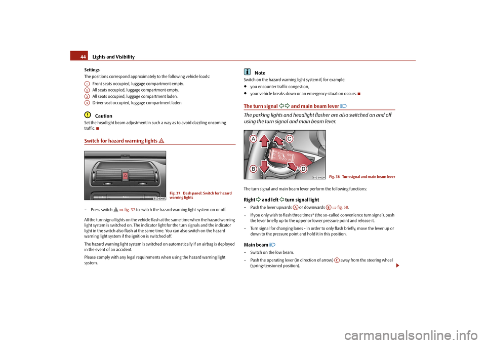
traffic.Switch for hazard warning lights
– Press switch
fig. 37 to switch the hazard warning light system on or off.
All the turn signal lights on the vehicle flas h at the same time when the hazard warning
light system is switched on. The indicator light for the turn signals and the indicator
light in the switch also flash at the same time. You can also switch on the hazard
warning light system if the ignition is switched off.
The hazard warning light system is switched on automatically if an airbag is deployed
in the event of an accident.
Please comply with any legal requirements when using the hazard warning light
system.
Note
Switch on the hazard warning light system if, for example:
you encounter traffic congestion,
your vehicle breaks down or an emergency situation occurs.
The turn signal
and main beam lever
The parking lights and headlight flasher are also switched on and off
using the turn signal and main beam lever.The turn signal and main beam le ver perform the following functions:Right
and left
turn signal light
– Push the lever upwards or downwards fig. 38 .
– If you only wish to flash three times* (the so-called convenience turn signal), push
the lever briefly up to the upper or lower pressure point and release it.
– Turn signal for changing lanes - in order to only flash briefly, move the lever up or down to the pressure point and hold it in this position.Main beam
– Switch on the low beam.
– Push the operating lever (in direction of arrow) away from the steering wheel
(spring-tensioned position).
A-A1A2A3
Fig. 37 Dash panel: Switch for hazard
warning lights
Fig. 38 Turn signal and main beam lever
AA
AB
AC
s2bs.2.book Page 44 Monday, September 27, 2010 9:53 AM
Page 48 of 199
Lights and Visibility47
Using the system
Safety
Driving Tips
General Maintenance
Breakdown assistance
Technical Data
If the on-board voltage drops, the rear window heater is switched off automatically,
in order to provide sufficient electrical energy for the engine control.
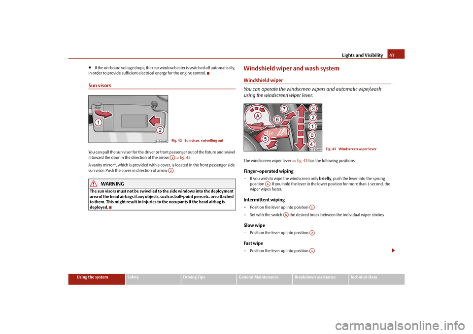
Sun visorsYou can pull the sun visor for the driver or front passenger out of the fixture and swivel
it toward the door in the direction of the arrow fig. 42 .
A vanity mirror*, which is provided with a cover, is located in the front passenger side
sun visor. Push the cover in direction of arrow .
WARNING
The sun visors must not be swivelled to the side windows into the deployment
area of the head airbags if any objects, such as ball-point pens etc. are attached
to them. This might result in injuries to the occupants if the head airbag is
deployed.
Windshield wiper and wash systemWindshield wiper
You can operate the windscreen wipers and automatic wipe/wash
using the windscreen wiper lever.The windscreen wiper lever fig. 43 has the following positions:Finger-operated wiping– If you wish to wipe the windscreen only briefly, push the lever into the sprung
position . If you hold the lever in the lower position for more than 1 second, the
wiper wipes faster.Intermittent wiping– Position the lever up into position .
– Set with the switch the desired brea k between the individual wiper strokesSlow wipe– Position the lever up into position .Fast wipe– Position the lever up into position .
Fig. 42 Sun visor: swivelling outA1A2
Fig. 43 Windscreen wiper lever
A4
A1
AA
A2A3
s2bs.2.book Page 47 Monday, September 27, 2010 9:53 AM
Page 53 of 199
Seats and Stowage
52
Seats and StowageFront seatsBasic informationThe front seats have a wide range of differ ent settings and can thus be matched to the
physical characteristics of the driver and front passenger. Correct adjustment of the
seats is particularly important for:
safely and quickly reaching the controls,
a relaxed, fatigue-free body position,
achieving the maximum protection offered by the seat belts and the airbag
system.
WARNING
Never transport more occupants than the maximum seating in the vehicle.
Each occupant must correctly fasten the seat belt belonging to the seat.
Children must be fastened page 103, “Transporting children safely” with a
suitable restraint system.
The front seats and the head restraints must always be adjusted to match
the body size of the seat occupant as well as the seat belts must always be
correctly fastened in order to provide an optimal protection for you and your
occupants.
Keep your feet in the footwell at al l times while driving. Never place your
feet on the dash panel, out of the window or on the seats. This is particularly
important for the front seat passenger. You will be exposed to increased risk of
injury if it becomes necessary to apply the brake or in the event of an accident.
If an airbag is deployed, you may suffer fatal injuries when adopting an incor-
rect seated position!
It is important for the driver and front passenger to maintain a distance of at
least 25 cm from the steering wheel or dash panel. Not maintaining this
minimum distance will mean that the airbag system will not be able to properly
protect you - hazard! The front seats and the head restraints must always also
be correctly adjusted to match the body size of the occupant.
Ensure that there are no objects in the footwell as any objects may get
behind the pedals during a driving or braking manoeuvre. You would then no
longer be able to operate the clutch, to brake or accelerate.
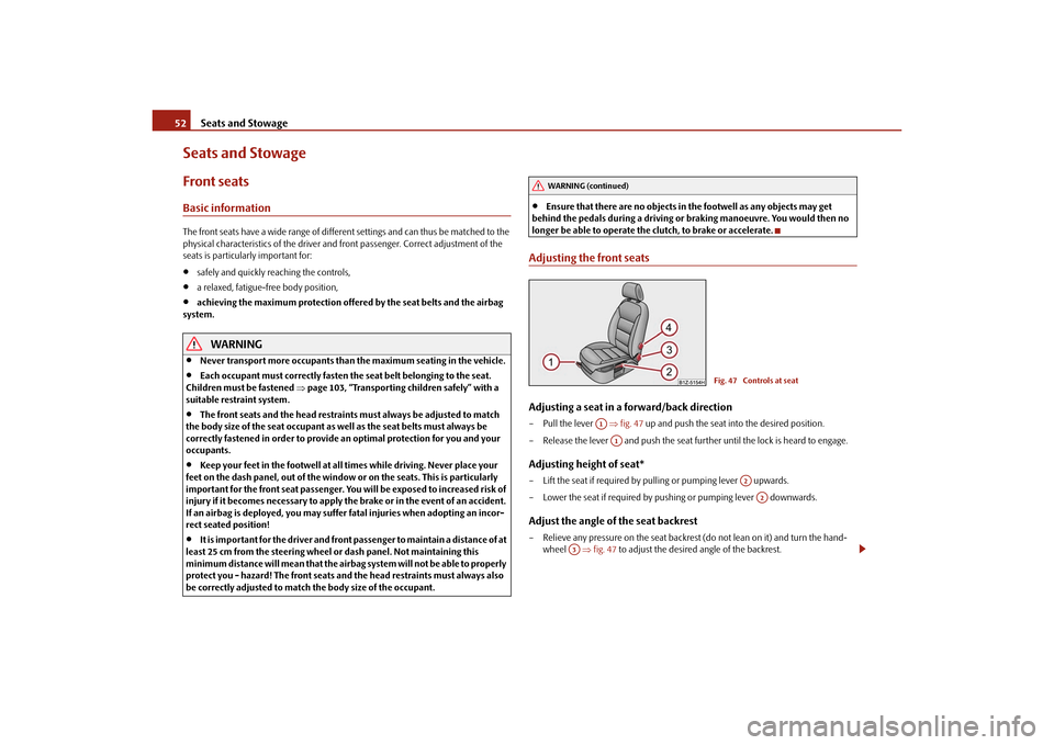
Adjusting the front seatsAdjusting a seat in a forward/back direction– Pull the lever fig. 47 up and push the seat into the desired position.
– Release the lever and push the seat further until the lock is heard to engage.Adjusting height of seat*– Lift the seat if required by pu lling or pumping lever upwards.
– Lower the seat if required by pushing or pumping lever downwards.Adjust the angle of the seat backrest– Relieve any pressure on the seat backrest (do not lean on it) and turn the hand- wheel fig. 47 to adjust the desired angle of the backrest.
WARNING (continued)
Fig. 47 Controls at seat
A1A1
A2A2
A3
s2bs.2.book Page 52 Monday, September 27, 2010 9:53 AM
Page 54 of 199
Seats and Stowage53
Using the system
Safety
Driving Tips
General Maintenance
Breakdown assistance
Technical Data
Adjusting lumbar support*– Turn the wheel until you have set the most comfortable curvature of the seat
upholstery in the area of your spine.
The driver's seat should be adjusted in such a way that the pedals can be fully pressed
to the floor with slightly bent legs.
The seat backrest on the driver's seat should be adjusted in such a way that the upper
point of the steering wheel can be easi ly reached with slightly bent arms.
WARNING
Only adjust the driver seat when the vehicle is stationary - risk of injury!
Take care when adjusting the seat! Adjusting the seat without care can lead
to bruises or injuries.
The seat backrests must not be angled too far back when driving otherwise
this will affect proper operation of the se at belts and of the airbag system - risk
of injury!
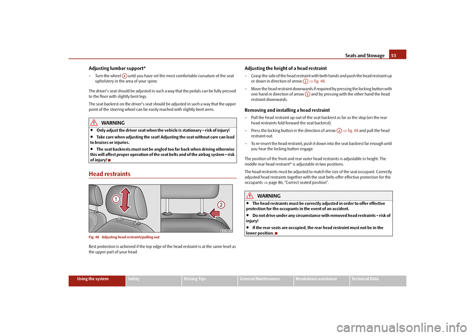
Head restraintsFig. 48 Adjusting head restraint/pulling outBest protection is achieved if the top edge of the head restraint is at the same level as
the upper part of your head.
Adjusting the height of a head restraint– Grasp the side of the head restraint with both hands and push the head restraint up
or down in direction of arrow fig. 48 .
– Move the head restraint downwards if required by pressing the locking button with one hand in direction of arrow and by pressing with the other hand the head
restraint downwards.Removing and installing a head restraint– Pull the head restraint up out of the seat backrest as far as the stop (on the rear
head restraints fold forward the seat backrest).
– Press the locking button in the direction of arrow fig. 48 and pull the head
restraint out.
– To re-insert the head restraint, push it do wn into the seat backrest far enough until
you hear the locking button engage.
The position of the front and rear outer head restraints is adjustable in height. The
middle rear head restraint* is adjustable in two positions.
The head restraints must be adjusted to ma tch the size of the seat occupant. Correctly
adjusted head restraints together with the seat belts offer effective protection for the
occupants page 86, “Correct seated position”.
WARNING
The head restraints must be correctly adjusted in order to offer effective
protection for the occupants in the event of an accident.
Do not drive under any circumstance with removed head restraints - risk of
injury!
If the rear seats are occupied, the rear head restraint must not be in the
lower position.
A4
A1A2
A2
s2bs.2.book Page 53 Monday, September 27, 2010 9:53 AM
Page 70 of 199
Seats and Stowage69
Using the system
Safety
Driving Tips
General Maintenance
Breakdown assistance
Technical Data
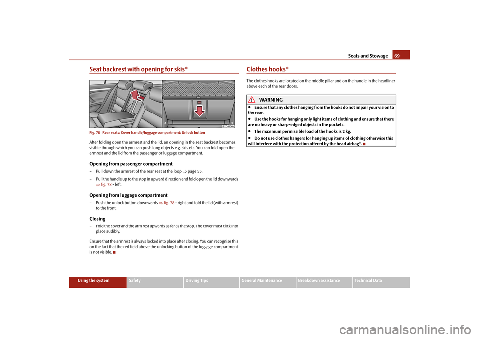
Seat backrest with opening for skis*Fig. 78 Rear seats: Cover handle/l uggage compartment: Unlock buttonAfter folding open the armrest and the lid, an opening in the seat backrest becomes
visible through which you can push long objects e.g. skis etc. You can fold open the
armrest and the lid from the passenger or luggage compartment.Opening from passenger compartment– Pull down the armrest of the rear seat at the loop page 55.
– Pull the handle up to the stop in upward direction and fold open the lid downwards fig. 78 - left.Opening from luggage compartment– Push the unlock button downwards fig. 78 - right and fold the lid (with armrest)
to the front.Closing– Fold the cover and the arm rest upwards as far as the stop. The cover must click into
place audibly.
Ensure that the armrest is always locked into place after closing. You can recognise this
on the fact that the red field above the unlocking button of the luggage compartment
is not visible.
Clothes hooks*The clothes hooks are located on the middle pillar and on the handle in the headliner
above each of the rear doors.
WARNING
Ensure that any clothes hanging from the hooks do not impair your vision to
the rear.
Use the hooks for hanging only light item s of clothing and ensure that there
are no heavy or sharp-edged objects in the pockets.
The maximum permissible load of the hooks is 2 kg.
Do not use clothes hangers for hanging up items of clothing otherwise this
will interfere with the protection offered by the head airbag*.
s2bs.2.book Page 69 Monday, September 27, 2010 9:53 AM
Page 78 of 199
Starting-off and Driving77
Using the system
Safety
Driving Tips
General Maintenance
Breakdown assistance
Technical Data
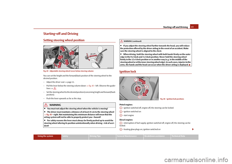
Starting-off and DrivingSetting steering wheel positionFig. 83 Adjustable steering wheel: Lever below steering columnYou can set the height and the forward/back position of the steering wheel to the
desired position.
– Adjust the driver seat page 11.
– Pull the lever below the steering column down fig. 83 - left. Observe the guide-
lines .
– Set the steering wheel to the desired position (concerning height and forward/back position).
– Push the lever upwards as far as the stop.
WARNING
You must not adjust the steering wheel when the vehicle is moving!
The driver must maintain a distance of at least 25 cm to the steering wheel
fig. 83 - right. Not maintaining this minimum distance will mean that the
airbag system will not be able to properly protect you - hazard!
For safety reasons the lever must always be firmly pushed up to avoid the
steering wheel altering its po sition unintentionally when driving - risk of acci-
dent!
If you adjust the steering wheel furthe r towards the head, you will reduce
the protection offered by the driver airbag in the event of an accident. Make
sure the steering wheel is aligned to the chest.
When driving, hold the steering wheel with both hands firmly on the outer
edge in the 9 o'clock and 3 o'clock po sition. Never hold the steering wheel
firmly in the 12 o'clock position or in another way (e.g. in the middle of the
steering wheel or at the inne r steering wheel edge). In such cases, injuries to the
arms, the hands and the head can occur when the driver airbag is deployed.
Ignition lockPetrol engines
- ignition switched off, engine off, the steering can be locked.
- ignition switched on
- start engine
Diesel engines - interruption of fuel supply, ignition swit ched off, engine off, the steering can be
locked.
- heating glow plugs on, ignition switched on
WARNING (continued)
Fig. 84 Ignition lock positions
A1A2A3A1A2
s2bs.2.book Page 77 Monday, September 27, 2010 9:53 AM