heating SKODA OCTAVIA TOUR 2011 2.G / (1Z) Owner's Guide
[x] Cancel search | Manufacturer: SKODA, Model Year: 2011, Model line: OCTAVIA TOUR, Model: SKODA OCTAVIA TOUR 2011 2.G / (1Z)Pages: 183, PDF Size: 11.13 MB
Page 77 of 183
Starting-off and Driving
76
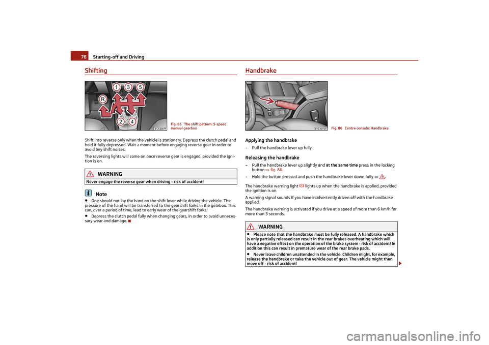
ShiftingShift into reverse only when the vehicle is stationary. Depress the clutch pedal and
hold it fully depressed. Wait a moment be fore engaging reverse gear in order to
avoid any shift noises.
The reversing lights will come on once reverse gear is engaged, provided the igni-
tion is on.
WARNING
Never engage the reverse gear when driving - risk of accident!
Note
•
One should not lay the hand on the shift lever while driving the vehicle. The
pressure of the hand will be transferred to the gearshift forks in the gearbox. This
can, over a period of time, lead to early wear of the gearshift forks.
•
Depress the clutch pedal fully when changing gears, in order to avoid unneces-
sary wear and damage.
HandbrakeApplying the handbrake– Pull the handbrake lever up fully.Releasing the handbrake– Pull the handbrake lever up slightly and at the same time press in the locking
button fig. 86.
– Hold the button pressed and push the handbrake lever down fully .
The handbrake warning light
lights up when the handbrake is applied, provided
the ignition is on.
A warning signal sounds if you have inadvertently driven off with the handbrake
applied.
The handbrake warning is activated if you drive at a speed of more than 6 km/h for
more than 3 seconds.
WARNING
•
Please note that the hand brake must be fully released. A handbrake which
is only partially released can result in the rear brakes overheating which will
have a negative effect on the operation of the brake system - risk of accident! In
addition this can result in premat ure wear of the rear brake pads.
•
Never leave children unattended in the vehicle. Children might, for example,
release the handbrake or take the vehicl e out of gear. The vehicle might then
move off - risk of accident!
Fig. 85 The shift pattern: 5-speed
manual gearbox
Fig. 86 Centre console: Handbrake
s2lk.2.book Page 76 Monday, April 18, 2011 7:41 AM
Page 107 of 183
Intelligent Technology
106
•
Changes to vehicle (e.g. on engine, on the brakes, on chassis or another combi-
nation of tyres and wheels) can influence the function of the ESP page 146,
“Accessories, changing and replacing parts”.
Electronic Differential Lock (EDL)*
The electronic differential lock prevents an individual wheel from
slipping.Models fitted with ESP are equipped with electronic differential lock (EDL).
General
The EDL makes it much easier, and sometimes at all possible, to start off, accelerate
and climb a steep hill when the conditions of the road surface are unfavourable.
Operating principle
The EDL is activated automatically, that is without any action on the part of the
driver. It monitors the speeds of the driven wheels with the aid of the ABS sensors.
Should only one drive wheel begin spinning on a slippery surface there will be an
appreciable difference in the speed of the driven wheels. The EDL function brakes
the slipping wheel and the differential transmits a greater driving force to the other
driven wheel. This control process is also accompanied by noises.
Overheating of the brakes
The EDL switches off automatically if unusually severe stresses exist in order to
avoid excessive heat genera tion in the disc brake on the wheel which is being
braked. The vehicle can continue to be driven and has the same characteristics as a
vehicle not fitted with EDL.
The EDL switches on again automatically as soon as the brake has cooled down.
WARNING
•
Carefully depress the accelerator when accelerating on uniformly slippery
road surfaces, such as ice and snow. The driven wheels might still spin despite
the EDL and affect the stability of the vehicle - risk of an accident!
•
You should always adapt your style of dr iving to the condition of road surface
and to the traffic situation even when your vehicle is fitted with EDL. The
increased safety offered must not temp t you to take greater risks than other-
wise - risk of an accident!
Note
•
If the ABS or ESP warning light comes on, this may also indicate a fault in the
EDL. Please have the vehicle inspected as soon as possible by a specialist garage.
•
Changes to vehicle (e.g. on engine, on the brakes, on chassis or another combi-
nation of tyres and wheels) can in fluence the function of the EDL page 146,
“Accessories, changing and replacing parts”.
Traction control system (TCS)
The traction control system prevents the driven wheels from spin-
ning when accelerating.General
The TCS makes it much easier, and sometimes at all possible, to start off, accelerate
and climb a steep hill when the conditions of the road surface are unfavourable.
Operating principle
The TCS switches on automatically when the engine is started and then conducts a
self-test. The system monitors the speeds of the driven wheels with the aid of the
ABS sensors. If the wheels are spinning, th e force transmitted to the road surface is
automatically adapted by reducing the engi ne speed. The system operates at all
speeds.
The TCS operates in combination with the ABS page 108, “Antilock brake system
(ABS)”. The TCS will not function if a fault exists in the ABS system.
The TCS warning light lights up in the instrument cluster when there is a fault on
the TCS
page 25.
During an intervention of th e system, the TCS warning light
flashes in the instru-
ment cluster page 25.
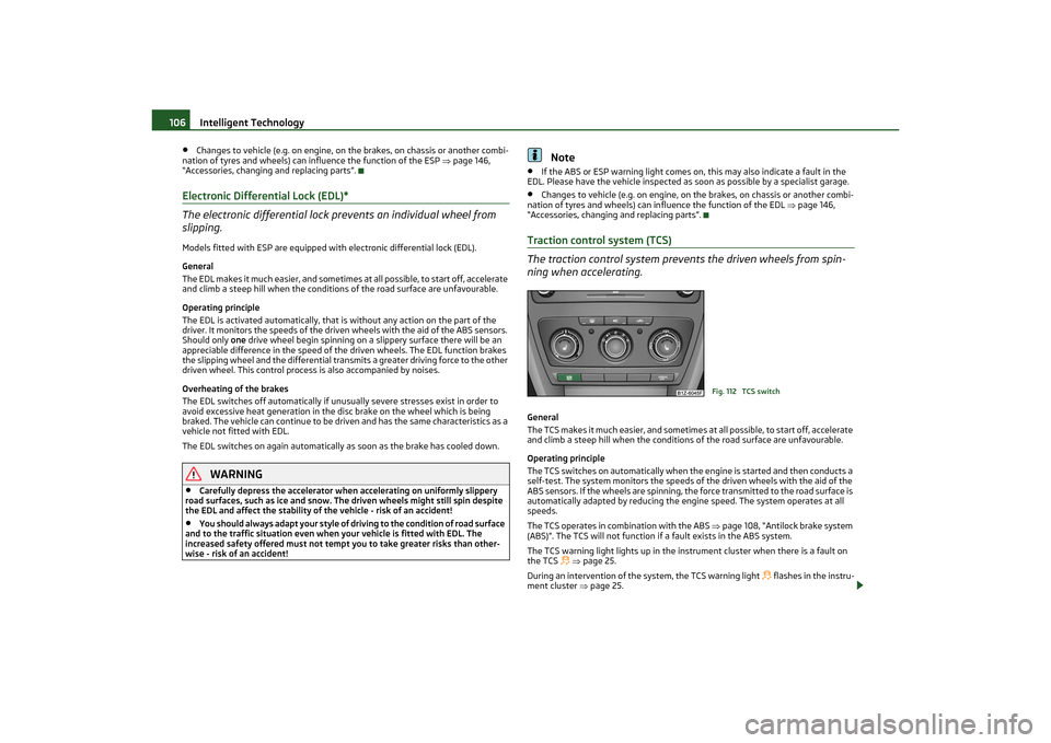
Fig. 112 TCS switch
s2lk.2.book Page 106 Monday, April 18, 2011 7:41 AM
Page 120 of 183
Towing a trailer119
Using the system
Safety
Driving Tips
General Maintenance
Breakdown assistance
Technical Data
Driving Tips
Particular caution is required when towing a trailer.– Do not, as far as possible, drive with your vehicle unladen and the trailer laden.
– Do not make full use of the legal maximum speeds. This applies in particular to downhill sections.
– Apply the brakes in good time.
– Keep a check on the coolant temperatur e gauge if the outside temperature is
high.
Distribution of weight
The distribution of the weight is very poor if your vehicle is unladen and the trailer
is laden. Maintain a particularly low speed if you cannot avoid driving with this
combination.
Driving speed
Do not drive faster than 80 km/hour for sa fety reasons. This also applies for coun-
tries in which higher speeds are allowed.
The fact that the driving stability of the vehicle + trailer combination reduces with
increasing speed means that the legally allowed speed should not be used when
there are unfavourable road, weather or wind conditions, particularly near accident
black spots.
You must always reduce your speed immedi ately as soon as you detect even just
the slightest swaying of the trailer. On no account attempt to stop the trailer from
“swaying” by accelerating.
Apply the brakes in good time! If the trailer is fitted with a trailer brake, apply the
brakes gently at first and then brake firmly . This will avoid brake jolts resulting from
the trailer wheels locking. Shift down gears in good time before negotiating a
downhill section to allow the engine to also act as a brake.
Engine overheating
Please keep a check on the coolant temper ature gauge if you have to negotiate a
lengthy slope in a low gear at a high engine speed when the outside temperature is
very high page 16, “Engine coolant temperature Display”.
If the needle of the coolant temperature gauge moves into the right-hand area or
even the red area of the scale, reduce yo ur speed immediately. Stop and switch off
the engine if the warning light
in the instrument cluster begins flashing. Wait a
few minutes and check the level of coolant in the coolant expansion bottle
page 134, “Inspecting the coolant level”. Please refer to the following guidelines
page 25, “Coolant temperature/coolant
level ”.
The coolant temperature can be reduced by switching on the heating.
Any increase in the cooling effect of the coolant fan through shifting down a gear
and increasing the engine speed is not possible since the fan speed is independent
of the engine speed. One should also not drop a gear for this reason when towing a
trailer as long as the engine can manage the slope without any drop in speed.
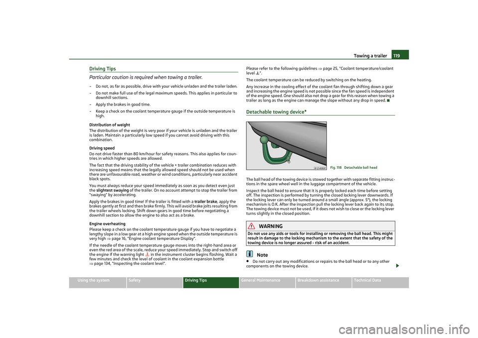
Detachable towing device*The ball head of the towing device is stow ed together with separate fitting instruc-
tions in the spare wheel well in the luggage compartment of the vehicle.
Inspect the ball head to ensure that it is properly locked each time before setting
off. The inspection is performed by turning the closed locking lever downwards. If
the locking lever can only be turned around a small angle (approx. 5°), the locking
mechanism is O.K. After the inspection pull the locking lever back again to its stop.
The towing device must not be used, if it does not wish to close or the locking lever
turns slightly in the closed position.
WARNING
Do not use any aids or tools for installing or removing the ball head. This might
result in damage to the locking mechanism to the extent that the safety of the
towing device is no longer assured - risk of an accident.
Note
•
Do not carry out any modifications or re pairs to the ball head or to any other
components on the towing device.
Fig. 118 Detachable ball head
s2lk.2.book Page 119 Monday, April 18, 2011 7:41 AM
Page 124 of 183
Taking care of your vehicle and cleaning the vehicle123
Using the system
Safety
Driving Tips
General Maintenance
Breakdown assistance
Technical Data
PolishingPolishing is only necessary if the paintwork of your vehicle has become unattractive
and if it is no longer possible to achieve a gloss with wax preservers.
You must treat the paintwork with a wax preserver if the polish you use does not
contain any preserving elements page 122.
We recommend using a preservative from Škoda genuine accessories offered by
your Škoda dealer.
Caution
•
You must not treat mat painted parts or plastic with polishing products or hard
wax.
•
Do not polish the paintwork of the vehicle in a dusty environment, otherwise the
paintwork can be scratched.
Chrome partsFirst clean the chrome parts with a damp cloth and then polish them with a soft, dry
cloth. If it does not prove to be adequate, use a chrome care product from Škoda
original accessories.
Caution
Do not polish the chrome parts in a du sty environment, otherwise they can be
scratched.Paint damageS li g ht da m a g e t o p a in tw o rk s uc h a s s c ra tc h e s, sc uf f s o r tra c e s o f c hi p da m a ge m ust
be touched up immediately with paint (Škoda painting pen) before any corrosion
can result. You can of course have this work carried out by authorised Škoda Service
Partners.
The authorised Škoda Service Partners have a range of matching touch-up pens or
spray cans available in the colour of your vehicle.
The paint number of the original paintwork of your vehicle is indicated on the
vehicle data sticker page 165.
Any corrosion which has already have formed must be removed thoroughly. Apply a
corrosion protection primer and then the paint to the affected point. You can of
course have this work carried out by authorised Škoda Service Partners.
Plastic partsExternal plastic parts are cleaned by norm al washing. Plastic parts and synthetic
leather can also be treated with special solvent-free plastic cleaning agents if a
damp cloth is not sufficient. Paint care products are not suitable for plastic parts.
Caution
Solvent-free cleaners attack the material and can damage it.WindowsOnly use a plastic ice scraper for removi ng snow and ice from the windows and
mirrors. You should not move the ice scraper forward and backward but in one direc-
tion on the window which yo u are cleaning in order to avoid any damage to the
surface of the glass.
You can best remove residues of rubber, oil, grease, wax or silicone by using a
special window cleaner or a special silicone remover.
You should also clean the windows regularly from the inside.
Do not use window leathers which you have used to polish the vehicle body to dry
off the windows. Residues of preservatives in the window leather can dirty the
window and reduce visibility.
Do not affix any stickers over the inside of the rear window to avoid damage to the
heating elements of the rear window heater.
We recommend using a preservative from Škoda genuine accessories offered by
your Škoda dealer.
Caution
Never remove snow or ice from the glass parts with warm or hot water - risk of
formation of cracks in the glass!The headlight lensesPlease do not use any aggressive cleaning or chemical solvent products for cleaning
the front headlights - risk of damage to the plastic lenses. Please use soap and
clean warm water.
s2lk.2.book Page 123 Monday, April 18, 2011 7:41 AM
Page 126 of 183
Taking care of your vehicle and cleaning the vehicle125
Using the system
Safety
Driving Tips
General Maintenance
Breakdown assistance
Technical Data
This wax protection does not require to be
inspected or re-treated. Please remove
any small amount of wax which flows out of the cavities at high temperatures with
a plastic scraper and clean the spot using petroleum cleaner.
WARNING
Safety and environmental protection regulations should observed when using
petroleum cleaner to remove wax - a risk of fire!Engine compartmentGood corrosion protection is very importan t, particularly in winter when one often
drives over its salt-strewn roads. One should therefore clean the whole engine
compartment before and after the salt spre ading period and treat with preservative
in order to prevent the salt from being destructive.
The authorised Škoda Service Partners have the cleaning agents and preservatives
recommended by Škoda and also the required equipment.
WARNING
•
It is necessary to observe the guidelin es given in the chapter before working
on the engine compartment page 131, “Working in the engine compartment”.
•
Let the engine cool down before cleaning the engine compartment.Caution
•
Engine cleaning may be only be un dertaken when the ignition is off.
•
It is recommended to cover the generator before washing the engine compart-
ment.For the sake of the environment
The dirty water produced by washing the engine has washed away petrol, and resi-
dues of grease and oil and should therefore be cleaned by an oil separator. This is
why engine washing should only be undertaken in a specialist garage or at a fuelling
station (when these are fitted with the required equipment).
Care of the interior of vehiclePlastic parts, artificial leather and clothsYou can clean plastic parts and artificial le ather with a moist cloth. You should only
treat such parts with special solvent-free plastic cleaning and care products it does
prove to be adequate.
Upholstery cloth and cloth trim on the d oors, luggage compartment cover, headliner
etc. are best treated with special cleaning products, using if necessary a dry foam
and a soft sponge or brush.
We recommend using a cleaning product from Škoda genuine accessories offered
by your Škoda dealer.
Caution
Solvent-free cleaners attack the material and can damage it.Fabric covers of electrically heated seatsDo not clean the seat covers moist as this may re sult in damage to the seat heating
system.
Clean such covers using special agents, for example dry foam.Natural leather
Natural leather requires quite particular care and attention.Leather should be treated from time to time according the following guidelines
depending on how much it is used.Normal cleaning– Clean soiled areas of the leather with slightly moistened cotton or woollen cloth.Severe soiling– Clean severely soiled areas with a cloth dipped in a mild soapy solution (2 spoon-
fuls of natural soap to 1 litre of water).
– Ensure that the leather is not soaked through at any point and that no water
gets into the stitching of the seams.
s2lk.2.book Page 125 Monday, April 18, 2011 7:41 AM
Page 130 of 183
Fuel129
Using the system
Safety
Driving Tips
General Maintenance
Breakdown assistance
Technical Data
Caution
•
Remove any fuel which has spilled onto the paintwork of your vehicle immedi-
ately - risk of paint damage!
•
Vehicles fitted with catalytic converter should never be allowed to let the fuel
tank to run completely empty. An irregular supply of fuel to the engine can result in
misfiring and unburnt fuel may get into the exhaust system, which may result in
overheating and damage to the catalytic converter.
•
Make sure that the valve is not pressed into the filler tube when inserting the
pump nozzle into the filler tube. Otherwis e you are unintentionally filling up the
volume, which in case of heat can cause an expansion of the fuel. This can lead to
an overflow of fuel or damage to parts of the fuel reservoir.
•
The fuel tank is full just as soon as the pump nozzle switches off for the first
time, provided the nozzle has been operated properly. Do not continue refuelling -
otherwise the expansion volume is filled up.
s2lk.2.book Page 129 Monday, April 18, 2011 7:41 AM
Page 134 of 183
Inspecting and replenishing133
Using the system
Safety
Driving Tips
General Maintenance
Breakdown assistance
Technical Data
– Pour in a suitable grade of oil in portions of 0.5 litres
page 166, “Engine oil
specifications”.
– Inspect the oil level page 132.
– Carefully screw on the cap of the filler opening and push the dipstick in fully.
WARNING
•
Avoid dripping oil onto hot parts of the engine when topping up will oil - a
risk of fire!
•
Read and observe the warning notes page 131, “Working in the engine
compartment” before working in the engine compartment.For the sake of the environment
The oil level must on no account extend beyond the range page 132. Oil will
otherwise be drawn in through the crankc ase ventilation and may pass through the
exhaust system to atmosphere. The oil ma y combust in the catalytic converter and
damage it.Changing engine oilThe engine oil must be changed at the intervals stated in the Service schedule or
according to the service interval indicator page 17, “Service Interval Display”.
WARNING
•
Only carry out the engine oil change, if you have the required professional
knowledge!
•
Read and observe the warning notes page 131, “Working in the engine
compartment” before working in the engine compartment.
•
First of all, let the engine cool down, wear an eye protection and gloves - risk
of caustic burns due to hot oil.Caution
You must not pour any additives into the engine oil - risk of engine damage!
Damage, which results from such produc t, are excluded from the warranty.
For the sake of the environment
•
You must on no account pour oil into the ground or into the sewage system.
•
In view of the problems involved in properly disposing of old oil, the necessary
special tools and the knowledge required for such work, we recommend that you
have the oil and oil filter change carried out by an authorised Škoda Service Partner.Note
After your skin has come in contact with the oil, you must thoroughly wash your
skin.Cooling systemCoolant
The job of the coolant is to cool the engine.The cooling system does not require any maintenance under normal operating
conditions. The coolant consists of water with a concentration of coolant additive
of 40 %. This mixture not only provides antifreeze prot ection down to -25 °C but
also protects the cooling and heating system from corrosion. It also prevents the
formation of scale and significantly increases the boiling point of the coolant.
You must therefore not reduce the concentration of antifreeze agent in the coolant
by adding water, also not during the summer months or in countries with a warm
climate. The concentration of coolant additive in the coolant must be at least 40
%.
You can increase the amount of antifreeze in the coolant if a higher concentration
of antifreeze is necessary for climatic reasons but only up to 60 % (antifreeze
protection down to approx. -40 °C). The antifreeze protection tails off above that
concentration.
Vehicles exported to countries with a co ld climate (e.g. Sweden, Norway, Finland)
are already factory-filled with a coolant wh ich offers antifreeze protection down to
about -35 °C. In these countries the concentr ation of coolant additive should be at
least 50 %.
Coolant
The cooling system is factory-filled with coolant (purple in colour), which complies
with the specification TL-VW 774 G.
We recommend that you use the same cool ant additive - G12 PLUS-PLUS (purple in
colour) for topping up the system.
Please contact an authorised Škoda Serv ice Partner if you have any questions
regarding the coolant or if you wish to fill up with a different coolant.
AA
s2lk.2.book Page 133 Monday, April 18, 2011 7:41 AM
Page 135 of 183
Inspecting and replenishing
134
An authorised Škoda Service Partner can also supply you with the correct coolant
additives.
Coolant quantity
Caution
•
Other coolant additives may cause operational problems which, in particular,
involves significantly reduci ng the anticorrosion effect.
•
Any faults or problems resulting from corrosion may cause a loss of coolant
and, as a consequence of this, re sult in major engine damage.
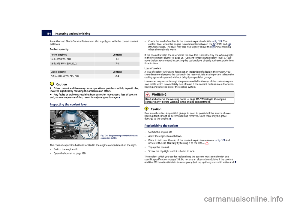
Inspecting the coolant levelThe coolant expansion bottle is located in the engine compartment on the right.
– Switch the engine off.
–Open the bonnet page 130. – Check the level of coolant in the coolant expansion bottle
fig. 124. The
coolant level when the engine is cold must lie between the (MIN) and
(MAX) markings. The level may also rise slightly above the (MAX) marking
when the engine is warm.
If the coolant level in the reservoir is too low, this is indicated by the warning light
in the instrument cluster page 25, “Coolant temperature/coolant level ”. We
nevertheless recommend inspecting the coolant level directly at the reservoir from
time to time.
Loss of coolant
A loss of coolant is first and foremost an indication of a leak in the system. You
should not merely top up the coolant in the re servoir. It is also important to have the
cooling system inspected without delay by a specialist garage.
Losses can only occur through the pressure relief in the cap of the coolant expan-
sion bottle which is completely free of leaks if the coolant boils as a result of over-
heating and is forced out of the cooling system.
WARNING
Read and observe the warning notes page 131, “Working in the engine
compartment” before working in the engine compartment.
Caution
One should contact a specialist garage as soon as possible if the source of over-
heating itself cannot be determined and removed, since there may be grave
damage to the engine.Replenishing the coolant– Switch the engine off.
– Allow the engine to cool down.
– Place a cloth over the cap of the coolant expansion reservoir fig. 124 and
unscrew the cap carefully by turning it to the left .
– Top up the coolant.
– Screw the cap tight until it is heard to lock.
The coolant which you use for replenishing the system, must comply with one
specific specification page 133. Do not use an altern ative additive if the coolant
additive G13 is not available in an emergency. Just top up the system with water and
Petrol engines
Content
1.4 ltr./59 kW - EU4
7.1
1.6 ltr./75 kW - EU4, EU2
7.4
Diesel engine
Content
2.0 ltr./81 kW TDI CR - EU4
8.4
Fig. 124 Engine compartment: Coolant
expansion bottle
Ab
Aa
Aa
s2lk.2.book Page 134 Monday, April 18, 2011 7:41 AM
Page 158 of 183
Fuses and light bulbs157
Using the system
Safety
Driving Tips
General Maintenance
Breakdown assistance
Technical Data
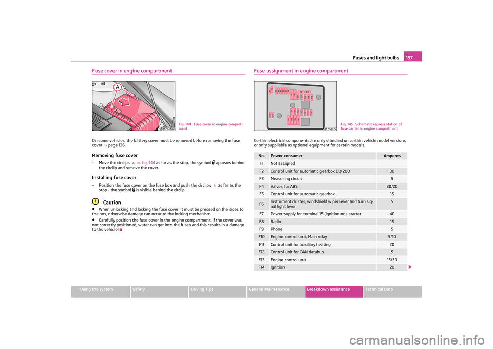
Fuse cover in engine compartmentOn some vehicles, the battery cover must be removed before removing the fuse
cover page 136.Removing fuse cover–Move the circlips fig. 144 as far as the stop, the symbol
appears behind
the circlip and remove the cover.
Installing fuse cover– Position the fuse cover on the fuse box and push the circlips as far as the stop - the symbol
is visible behind the circlip.
Caution
•
When unlocking and locking the fuse cover, it must be pressed on the sides to
the box, otherwise damage can occur to the locking mechanism.
•
Carefully position the fuse cover in the engine compartment. If the cover was
not correctly positioned, water can get into the fuses and this results in a damage
to the vehicle!
Fuse assignment in engine compartmentCertain electrical components are only st andard on certain vehicle model versions
or only suppliable as optional equipment for certain models.
Fig. 144 Fuse cover in engine compart-
ment
A
A
No.
Power consumer
Amperes
F1
Not assigned
F2
Control unit for automatic gearbox DQ 200
30
F3
Measuring circuit
5
F4
Valves for ABS
30/20
F5
Control unit for automatic gearbox
15
F6
Instrument cluster, windshield wiper lever and turn sig-
nal light lever
5
F7
Power supply for terminal 15 (ignition on), starter
40
F8
Radio
15
F9
Phone
5
F10
Engine control unit, Main relay
5/10
F11
Control unit for auxiliary heating
20
F12
Control unit for CAN databus
5
F13
Engine control unit
15/30
F14
Ignition
20
Fig. 145 Schematic representation of
fuse carrier in engine compartment
s2lk.2.book Page 157 Monday, April 18, 2011 7:41 AM
Page 159 of 183
Fuses and light bulbs
158
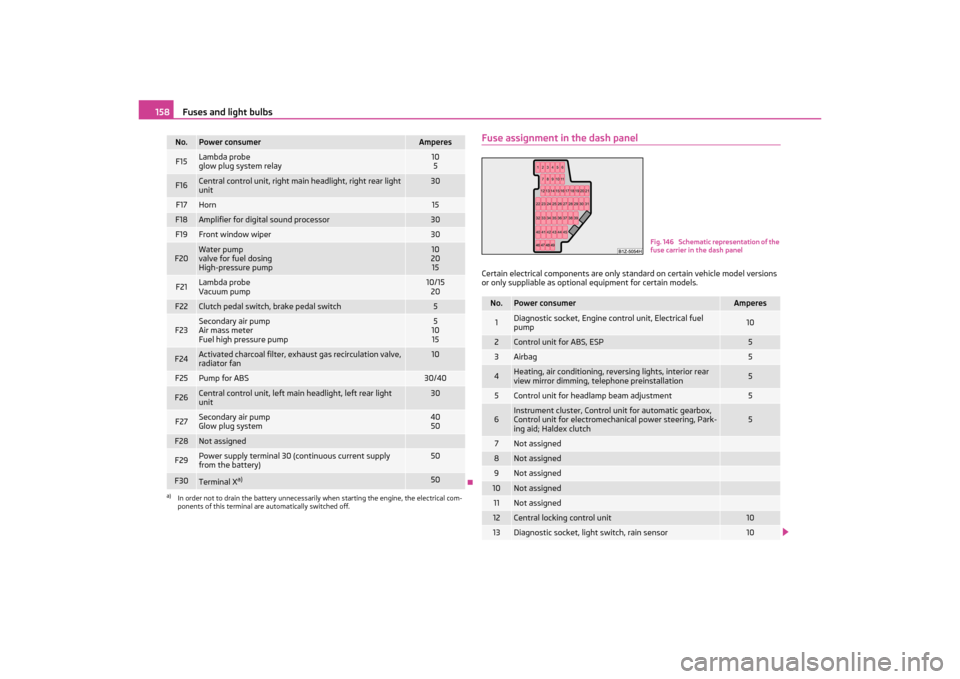
Fuse assignment in the dash panelCertain electrical components are only st andard on certain vehicle model versions
or only suppliable as optional equipment for certain models.
F15
Lambda probe
glow plug system relay
10
5
F16
Central control unit, right main headlight, right rear light
unit
30
F17
Horn
15
F18
Amplifier for digital sound processor
30
F19
Front window wiper
30
F20
Water pump
valve for fuel dosing
High-pressure pump
10
20
15
F21
Lambda probe
Vacuum pump
10/15 20
F22
Clutch pedal switch, brake pedal switch
5
F23
Secondary air pump
Air mass meter
Fuel high pressure pump
5
10
15
F24
Activated charcoal filter, exha ust gas recirculation valve,
radiator fan
10
F25
Pump for ABS
30/40
F26
Central control unit, left main headlight, left rear light
unit
30
F27
Secondary air pump
Glow plug system
40 50
F28
Not assigned
F29
Power supply terminal 30 (continuous current supply
from the battery)
50
F30
Terminal X
a)
50
a)In order not to drain the battery unnecessarily when starting the engine, the electrical com-
ponents of this terminal are automatically switched off.No.
Power consumer
Amperes
No.
Power consumer
Amperes
1
Diagnostic socket, Engine control unit, Electrical fuel
pump
10
2
Control unit for ABS, ESP
5
3
Airbag
5
4
Heating, air conditioning, reversing lights, interior rear
view mirror dimming, telephone preinstallation
5
5
Control unit for headlamp beam adjustment
5
6
Instrument cluster, Control unit for automatic gearbox,
Control unit for electromechanical power steering, Park-
ing aid; Haldex clutch
5
7
Not assigned
8
Not assigned
9
Not assigned
10
Not assigned
11
Not assigned
12
Central locking control unit
10
13
Diagnostic socket, light switch, rain sensor
10
Fig. 146 Schematic representation of the
fuse carrier in the dash panel
s2lk.2.book Page 158 Monday, April 18, 2011 7:41 AM