heating SKODA OCTAVIA TOUR 2011 2.G / (1Z) Owner's Manual
[x] Cancel search | Manufacturer: SKODA, Model Year: 2011, Model line: OCTAVIA TOUR, Model: SKODA OCTAVIA TOUR 2011 2.G / (1Z)Pages: 183, PDF Size: 11.13 MB
Page 4 of 183
Contents3
Using the system
Safety
Driving Tips
General Maintenance
Breakdown assistance
Technical Data
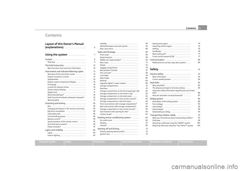
ContentsLayout of this Owner's Manual
(explanations)
. . . . . . . . . . . . . . . . . . . . . . . . . .
Using the system
. . . . . . . . . . . . . . . . . . . . .
Cockpit
. . . . . . . . . . . . . . . . . . . . . . . . . . . . . . . . . . . . . . . .
Overview . . . . . . . . . . . . . . . . . . . . . . . . . . . . . . . . . . . .
The brief instruction
. . . . . . . . . . . . . . . . . . . . . . . . . .
Basic functions and important information . . . . .
Instruments and Indicator/Warning Lights
. .
Overview of the instrument cluster . . . . . . . . . . . .
Engine revolutions counter . . . . . . . . . . . . . . . . . . . .
Speedometer . . . . . . . . . . . . . . . . . . . . . . . . . . . . . . . . .
Engine coolant temperature Display . . . . . . . . . . .
Fuel gauge . . . . . . . . . . . . . . . . . . . . . . . . . . . . . . . . . . .
Counter for distance driven . . . . . . . . . . . . . . . . . . .
Service Interval Display . . . . . . . . . . . . . . . . . . . . . . .
Digital clock . . . . . . . . . . . . . . . . . . . . . . . . . . . . . . . . . .
Recommended gear* . . . . . . . . . . . . . . . . . . . . . . . . .
Multi-functional indicator (onboard computer)* .
Warning lights . . . . . . . . . . . . . . . . . . . . . . . . . . . . . . . .
Unlocking and locking
. . . . . . . . . . . . . . . . . . . . . . . .
Key . . . . . . . . . . . . . . . . . . . . . . . . . . . . . . . . . . . . . . . . . .
Changing the battery in the remote control key
Electronic immobiliser . . . . . . . . . . . . . . . . . . . . . . . .
Child safety lock . . . . . . . . . . . . . . . . . . . . . . . . . . . . . .
Central locking system . . . . . . . . . . . . . . . . . . . . . . . .
Remote control* . . . . . . . . . . . . . . . . . . . . . . . . . . . . . .
Synchronisation of the remote control . . . . . . . . .
Anti-theft alarm system* . . . . . . . . . . . . . . . . . . . . . .
Power windows* . . . . . . . . . . . . . . . . . . . . . . . . . . . . .
Lights and Visibility
. . . . . . . . . . . . . . . . . . . . . . . . . . .
Lights . . . . . . . . . . . . . . . . . . . . . . . . . . . . . . . . . . . . . . . .
Interior lighting . . . . . . . . . . . . . . . . . . . . . . . . . . . . . . . Visibility . . . . . . . . . . . . . . . . . . . . . . . . . . . . . . . . . . . . .
Windshield wiper and wash system . . . . . . . . . . . .
Rear-view mirror . . . . . . . . . . . . . . . . . . . . . . . . . . . . .
Seats and Stowage
. . . . . . . . . . . . . . . . . . . . . . . . . . .
Front seats . . . . . . . . . . . . . . . . . . . . . . . . . . . . . . . . . .
Head restraints . . . . . . . . . . . . . . . . . . . . . . . . . . . . . . .
Middle rear head restraint* . . . . . . . . . . . . . . . . . . . .
Rear seats . . . . . . . . . . . . . . . . . . . . . . . . . . . . . . . . . . .
Pedals . . . . . . . . . . . . . . . . . . . . . . . . . . . . . . . . . . . . . . .
luggage compartment . . . . . . . . . . . . . . . . . . . . . . . .
Net partition* (Combi) . . . . . . . . . . . . . . . . . . . . . . . .
The roof rack* . . . . . . . . . . . . . . . . . . . . . . . . . . . . . . . .
Cup holder . . . . . . . . . . . . . . . . . . . . . . . . . . . . . . . . . . .
Note holder . . . . . . . . . . . . . . . . . . . . . . . . . . . . . . . . . .
Ashtray* . . . . . . . . . . . . . . . . . . . . . . . . . . . . . . . . . . . . .
Cigarette lighter*, power sockets . . . . . . . . . . . . . .
Storage compartments . . . . . . . . . . . . . . . . . . . . . . .
Overview . . . . . . . . . . . . . . . . . . . . . . . . . . . . . . . . . . . .
Storage compartment on the front passenger side
Storage compartment on the driver's side . . . . . .
Storage compartment on the dash panel . . . . . . .
Storage compartment in front centre console* .
Storage compartment in the front doors . . . . . . .
Front seat armrest with storage compartment*
Rear seat armrest with storage compartment* .
Storage compartment in re ar centre console* . .
Seat backrest with opening for skis* . . . . . . . . . . .
Clothes hooks* . . . . . . . . . . . . . . . . . . . . . . . . . . . . . . .
Heating and air conditioning system
. . . . . . . .
Air outlet vents . . . . . . . . . . . . . . . . . . . . . . . . . . . . . .
Heating . . . . . . . . . . . . . . . . . . . . . . . . . . . . . . . . . . . . . .
Climatic* . . . . . . . . . . . . . . . . . . . . . . . . . . . . . . . . . . . . .
Starting-off and Driving
. . . . . . . . . . . . . . . . . . . . . .
Setting steering wheel position . . . . . . . . . . . . . . .
Ignition lock . . . . . . . . . . . . . . . . . . . . . . . . . . . . . . . . . . Starting the engine . . . . . . . . . . . . . . . . . . . . . . . . . . .
Switching off the engine . . . . . . . . . . . . . . . . . . . . . .
Shifting . . . . . . . . . . . . . . . . . . . . . . . . . . . . . . . . . . . . . .
Handbrake . . . . . . . . . . . . . . . . . . . . . . . . . . . . . . . . . . .
Rear parking aid* . . . . . . . . . . . . . . . . . . . . . . . . . . . . .
Cruise control system (CCS)* . . . . . . . . . . . . . . . . . .
Communication
. . . . . . . . . . . . . . . . . . . . . . . . . . . . . . .
Mobile phones and two-way radio systems . . . .
Safety
. . . . . . . . . . . . . . . . . . . . . . . . . . . . . . . . . . . . . .
Passive Safety
. . . . . . . . . . . . . . . . . . . . . . . . . . . . . . . .
Basic information . . . . . . . . . . . . . . . . . . . . . . . . . . . .
Correct seated position . . . . . . . . . . . . . . . . . . . . . . .
Seat belts
. . . . . . . . . . . . . . . . . . . . . . . . . . . . . . . . . . . . .
Why seat belts? . . . . . . . . . . . . . . . . . . . . . . . . . . . . . .
The physical principle of a frontal collision . . . . .
Important safety information regarding the use of seat
belts . . . . . . . . . . . . . . . . . . . . . . . . . . . . . . . . . . . . . . . .
How are seat belts correctly fastened? . . . . . . . .
Airbag system
. . . . . . . . . . . . . . . . . . . . . . . . . . . . . . . .
Description of the airbag system . . . . . . . . . . . . . .
Front airbags . . . . . . . . . . . . . . . . . . . . . . . . . . . . . . . .
side airbags* . . . . . . . . . . . . . . . . . . . . . . . . . . . . . . . . .
Head airbags* . . . . . . . . . . . . . . . . . . . . . . . . . . . . . . . .
Deactivating an airbag . . . . . . . . . . . . . . . . . . . . . . . .
Transporting children safely
. . . . . . . . . . . . . . . . .
What you should know about transporting children!
Child seat . . . . . . . . . . . . . . . . . . . . . . . . . . . . . . . . . . . .
Attaching a child seat using the “ISOFIX” system
Attaching child seat using the “Top Tether”* system
6799101015151516161616171718182129292930303034353637404043
4445484949505051535357585960606061616262626363636464646566666769737373
7475767677778080818181828585858687898990929495979799102103
s2lk.2.book Page 3 Monday, April 18, 2011 7:41 AM
Page 10 of 183
Cockpit9
Using the system
Safety
Driving Tips
General Maintenance
Breakdown assistance
Technical Data
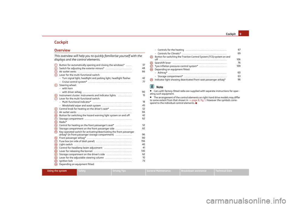
CockpitOverviewThis overview will help you to quickly familiarise yourself with the
displays and the control elements.
Button for automatically opening and closing the windows* . . . . .
Switch for adjusting the exterior mirrors* . . . . . . . . . . . . . . . . . . . . . . .
Air outlet vents . . . . . . . . . . . . . . . . . . . . . . . . . . . . . . . . . . . . . . . . . . . . . . .
Lever for the multi-functional switch:
−Turn signal light, headlight and parking light, headlight flasher
− Cruise control system* . . . . . . . . . . . . . . . . . . . . . . . . . . . . . . . . . . . . . .
Steering wheel:
− with horn
− with driver airbag . . . . . . . . . . . . . . . . . . . . . . . . . . . . . . . . . . . . . . . . . . .
Instrument cluster: Instruments and indicator lights . . . . . . . . . . . .
Lever for the multi-functional switch:
− Multi-functional indicator* . . . . . . . . . . . . . . . . . . . . . . . . . . . . . . . . . .
− Windshield wiper and wash system . . . . . . . . . . . . . . . . . . . . . . . . . .
Control knob for heating on the driver's seat* . . . . . . . . . . . . . . . . . . .
Air outlet vents . . . . . . . . . . . . . . . . . . . . . . . . . . . . . . . . . . . . . . . . . . . . . . .
Button for switching the hazard warning light system on and off
Storage compartment . . . . . . . . . . . . . . . . . . . . . . . . . . . . . . . . . . . . . . . . .
Radio*
Control for heating on the front passenger's seat* . . . . . . . . . . . . . .
Storage compartment on the front passenger side . . . . . . . . . . . . . .
Key-operated switch for activating /deactivating the front passenger
airbag* (in front passenger storage compartment) . . . . . . . . . . . . . .
Front passenger airbag* . . . . . . . . . . . . . . . . . . . . . . . . . . . . . . . . . . . . . . .
Fuse box (on side of dash panel) . . . . . . . . . . . . . . . . . . . . . . . . . . . . . . .
Light switch . . . . . . . . . . . . . . . . . . . . . . . . . . . . . . . . . . . . . . . . . . . . . . . . . .
Control for headlamp beam adjustment . . . . . . . . . . . . . . . . . . . . . . . .
Lever for releasing the bonnet . . . . . . . . . . . . . . . . . . . . . . . . . . . . . . . . .
Storage compartment on the driver's side . . . . . . . . . . . . . . . . . . . . . .
Lever for the adjustable steering column . . . . . . . . . . . . . . . . . . . . . . .
Ignition lock . . . . . . . . . . . . . . . . . . . . . . . . . . . . . . . . . . . . . . . . . . . . . . . . . .
Depending on equipment fitted: −
Controls for the heating . . . . . . . . . . . . . . . . . . . . . . . . . . . . . . . . . . . .
− Controls for Climatic* . . . . . . . . . . . . . . . . . . . . . . . . . . . . . . . . . . . . . . .
Button for switching the Traction Control System (TCS) system on and
off . . . . . . . . . . . . . . . . . . . . . . . . . . . . . . . . . . . . . . . . . . . . . . . . . . . . . . . . . . .
Gearshift lever . . . . . . . . . . . . . . . . . . . . . . . . . . . . . . . . . . . . . . . . . . . . . . .
Tyre inflation pressure-control system* . . . . . . . . . . . . . . . . . . . . . . . .
Depending on equipment fitted:
− Ashtray* . . . . . . . . . . . . . . . . . . . . . . . . . . . . . . . . . . . . . . . . . . . . . . . . . . .
− Storage compartment* . . . . . . . . . . . . . . . . . . . . . . . . . . . . . . . . . . . . .
Indicator light showing deactivated front seat passenger airbag*
Note
•
Cars with factory-fitted radio are supplie d with separate instructions for oper-
ating such equipment.
•
The arrangement of the control elements on right-hand drive models may differ
to some extent from that shown in page 8, fig. 1 . However the symbols corre-
spond to the individual control elements.
A1
37
A2
48
A3
66
A4
4277
A5
90
A6
15
A7
1845
A8
52
A9
66
A10
42
A11
62
A12A13
52
A14
62
A15
96
A16
90
A17
156
A18
40
A19
41
A20
130
A21
62
A22
10
A23
73
A24
6769
A25
106
A26
76
A27
109
A28
6063
A29
96
s2lk.2.book Page 9 Monday, April 18, 2011 7:41 AM
Page 12 of 183
The brief instruction11
Using the system
Safety
Driving Tips
General Maintenance
Breakdown assistance
Technical Data
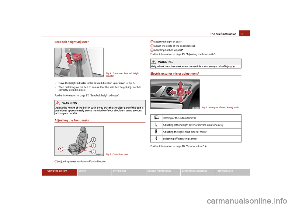
Seat belt height adjuster– Move the height adjuster in the desired direction up or down fig. 4 .
– Then pull firmly on the belt to ensure that the seat belt height adjuster has
correctly locked in place.
Further information page 87, “Seat belt height adjuster”.
WARNING
Adjust the height of the belt in such a wa y that the shoulder part of the belt is
positioned approximately across the midd le of your shoulder - on no account
across your neck!Adjusting the front seats Adjusting a seat in a forward/back direction Adjusting height of seat*
Adjust the angle of the seat backrest
Adjusting lumbar support*
Further information page 49, “Adjusting the front seats”.
WARNING
Only adjust the driver seat when the vehicle is stationary - risk of injury!Electric exterior mirror adjustment*Further information page 48, “Exterior mirror”.
Fig. 4 Front seat: Seat belt height
adjusterFig. 5 Controls at seat
A1
Heating of the external mirror
Adjusting left and right exterior mirrors simultaneously
Adjusting the right-hand exterior mirror
Switching off operating control
A2A3A4
Fig. 6 Inner part of door: Rotary knob
s2lk.2.book Page 11 Monday, April 18, 2011 7:41 AM
Page 17 of 183
Instruments and Indicator/Warning Lights
16For the sake of the environment
Shifting up early helps you save fuel and reduce the operating noise of your
vehicle.SpeedometerThe speedometer shows the current speed of the car.Engine coolant temperature DisplayThe coolant temperature gauge page 15, fig. 15 operates only when the igni-
tion is switched on.
In order to avoid any damage to the engine, please pay attention to the following
notes regarding the temperature ranges:
Cold range
If the pointer is in the left-hand area of the scale it means that the engine has not
yet reached its operating temperature. Avoid running at high engine speeds, at full
throttle and at severe engine loads.
The operating range
The engine has reached its operating temp erature as soon as the pointer moves
into the mid-range of the scale. The pointer may also move further to the right at
high engine loads and high outside temperat ures. This is not critical provided the
warning symbol
in the instrument cluster does not flash.
If the symbol
in the instrument cluster flashes it means that either the coolant
temperature is too high or the coolant level is too low. Observe the guidelines
page 25, “Coolant temperature/coolant level ”.
WARNING
Pay attention to the warning notes page 131, “Working in the engine compart-
ment” before opening the bonnet and inspecting the coolant level.
Caution
Additional headlights and other attached components in front of the fresh air inlet
impair the cooling efficiency of the coolant. There is then a risk of the engine over-
heating at high outside temperatures and high engine loads!
Fuel gaugeThe fuel gauge page 15, fig. 15 only works when the ig nition is switched on.
The fuel tank has a capacity of ab out 55 litres. The warning symbol
in the instru-
ment cluster lights up when the pointer reaches the reserve marking. There are
now about 9 litres of fuel remaining in the tank. This symbol is a reminder for you,
that you must refuel .
An acoustic signal sounds as an additional reminder.
Caution
Never run the fuel tank completely empty! The irregular supply of the fuel system
can lead to irregular running of the engine. Unburnt fuel may get into the exhaust
system and damage the catalytic converter.Counter for distance drivenThe distance which you have driven with yo ur vehicle is shown in kilometres (km).
In some countries the measuring unit “mile” is used.
Reset button
Hold the reset button page 15, fig. 15 pressed for approx. 1 second. The trip
counter is reset to zero.
Trip counter for distance driven
The trip counter shows the distance driven since the time the trip counter was last
erased. The trip is shown in steps of 100 metres or 1/10 of a mile.
Odometer
The odometer indicates the total distance in kilometres or miles which the vehicle
has been driven.
Fault display
If there is a fault in the instrument cluster Error will appear in the display. Contact a
specialist garage.
WARNING
Never seek to adjust the trip counter fo r distance driven while driving for safety
reasons!
A3
A6
A5
s2lk.2.book Page 16 Monday, April 18, 2011 7:41 AM
Page 45 of 183
Lights and Visibility
44
•
the ignition is switched on.
•
auto switch-off - about 30 seconds after all the doors have been closed.
If the doors remain open, the switch in position
, the interior lighting switches
off automatically after around 10 minutes to stop the battery from running down.
Note
We recommend having these bulbs replaced by a specialist garage.Vehicle interior lighting version 2Switching on the interior lighting– Turn the switch to position
fig. 40 .
Switching off the interior lighting– Turn the switch to position O.Operation of the lamp using the door switch– Turn the switch to position
.
The same principles apply for interior lighting version 2 as for page 43, “Lighting
of the interior of the vehicle - Version 1”.
Luggage compartment lightThe lighting comes on automatically when the boot lid is opened. If the lid remains
open for more than about 10 minutes, th e luggage compartment lighting switches
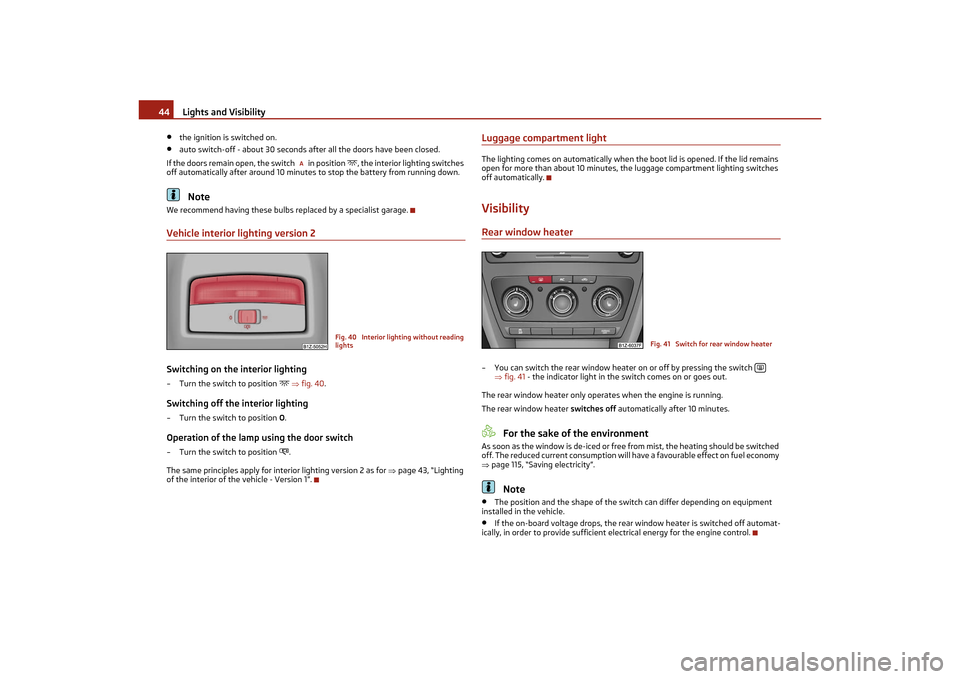
off automatically.VisibilityRear window heater– You can switch the rear window heater on or off by pressing the switch
fig. 41 - the indicator light in the switch comes on or goes out.
The rear window heater only operates when the engine is running.
The rear window heater switches off automatically after 10 minutes.
For the sake of the environment
As soon as the window is de-iced or free from mist, the heating should be switched
off. The reduced current consumption will ha ve a favourable effect on fuel economy
page 115, “Saving electricity”.
Note
•
The position and the shape of the switch can differ depending on equipment
installed in the vehicle.
•
If the on-board voltage drop s, the rear window heater is switched off automat-
ically, in order to provide sufficient electrical energy for the engine control.
A
Fig. 40 Interior lighting without reading
lights
Fig. 41 Switch for rear window heater
s2lk.2.book Page 44 Monday, April 18, 2011 7:41 AM
Page 47 of 183
Lights and Visibility
46
Automatic wipe/wash for windscreen
– Pull the lever towards the steering wheel into sprung position , the wash system sprays immediately, the windscreen wiper starts wiping a little later. The
wash system and the windscreen wiper operate simultaneously at a speed of
more than 120 km/h.
– Release the lever. The windscreen wash system stops and the wiper continues for another 3 - 4 wiper strokes (depending on the period of spraying of the wind-
screen). At a speed of more than 2 km/h, the wiper wipes once again* 5 seconds
after the last wiper stroke in order to wipe the last drops from the windscreen.
This function can be activated/de activated by a specialist garage.Wiping the rear window pane*– Push the lever away from the steering wheel into position - the widescreen
wiper will operate every 6 seconds.Automatic wipe/wash for the rear window pane*– Press the lever from the steering wheel forward into the sprung position , the
wash system sprays immediately, the windscreen wiper starts wiping a little
later. As long as you hold the lever in this position, the wiper operates as well as
the wash system.
– Letting go of the lever will cause the windscreen wash system to stop and the wiper to continue for another 2 - 3 wiper strokes (depending on the period of
spraying of the windscreen). The lever will stay in position after releasing it .Switching windscreen wipers off– Move the lever back into its home position .
After the windscreen wiper switches off each time or the ignition switches off for
the third time, the position of the windscreen wiper changes, this counteracts an
early fatigue of the wiper rubbers.
The windscreen wipers and the wash system only operate if the ignition is switched
on and the bonnet is closed
4).
If the intermittent wipe is switched on, the intervals are also controlled depending
on speed.
The rear window will be wiped again if the front window wipers are on when
reverse gear is selected. The windscreen washer nozzles are heated* when the ignition is switched on.
Top up with wash liquid
page 140.
Winter position
If the windscreen wipers are in rest position, they cannot be folded out from the
windscreen. For this reason we recommend adjusting the windscreen wipers in
winter so that they can be folded out from the windscreen easily. You can set this
rest position as follows:
•
Switch on the windscreen wipers.
•
Switch off the ignition. The windscreen wipers remain in the position in which
they were when switching off the ignition.
You can also use the service position page 47 as a winter position.
WARNING
•
Properly maintained windscreen wiper bl ades are essential for clear visibility
and safe driving page 47.
•
Do not use the windscreen washer system at low temperatures, without
heating the windscreen beforehand. Ot herwise the window cleaner could
freeze on the windscreen and restrict the view to the front.
•
The rain sensor only operates as a supp ort. The driver is not released from
the responsibility to set the function of the windscreen wipers manually
depending on the visibility conditions.Caution
In frosty weather, please first of all check whether the windscreen wiper blades are
not frozen to the windscreen before switching them on. Switching on windscreen
wipers when the blades are frozen to the windscreen may result in damage both to
the blades and the motor of the windscreen wipers!
Note
•
If the slower or the faster wiper setting is switched on page 45, fig. 43
and the vehicle speed decreases to below 4 km/h, the lower wiper step is switched
on automatically. At a speed increase of more than 8 km/h the previous wiper
setting is established again.
•
If there is an obstacle on the windscreen, the wiper will try to push away the
obstacle. If the obstacle continues to bloc k the wiper, the wiper stops after 5 cycles,
in order to avoid a damage to the wiper. Remove the obstacle and switch on the
wiper again.
4)On vehicles which do not have a contact switch for the bonnet, the windshield wiper and wash
system operates also when the bonnet is opened.
5
6
7
6
0
2
3
s2lk.2.book Page 46 Monday, April 18, 2011 7:41 AM
Page 49 of 183
Lights and Visibility
48
– With the other hand unlock the locking button in the direction of arrow and
remove the wiper blade.Attaching a wiper blade– Position the wiper blade onto the wiper arm and lock the locking button .
– Check whether the wiper blade is correctly attached.
The same remarks apply here as for page 47, “Replacing wiper blades for the
windscreen wipers”.Rear-view mirrorManual dimming interior rear-view mirrorBasic setting– Pull the lever on the bottom edge of the mirror forward.Dimming mirror– Pull the lever on the bottom edge of the mirror back.Exterior mirror
You can adjust the exterior mirrors electrically*.The exterior mirror heater only operates when the engine is running and up to an
outside temperature of +20 °C.
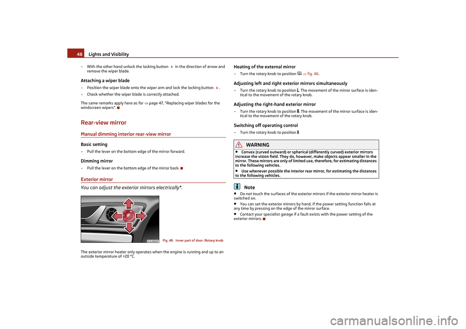
Heating of the external mirror – Turn the rotary knob to position
fig. 46 .
Adjusting left and right exterior mirrors simultaneously– Turn the rotary knob to position
. The movement of the mi rror surface is iden-
tical to the movement of the rotary knob.
Adjusting the right-hand exterior mirror– Turn the rotary knob to position
. The movement of the mirror surface is iden-
tical to the movement of the rotary knob.
Switching off operating control– Turn the rotary knob to position
.
WARNING
•
Convex (curved outward) or spherical (differently curved) exterior mirrors
increase the vision field. They do, howe ver, make objects appear smaller in the
mirror. These mirrors are only of limited use, therefore, for estimating distances
to the following vehicles.
•
Use whenever possible the interior rear mirror, for estimating the distances
to the following vehicles.Note
•
Do not touch the surfaces of the exterior mirrors if the exterior mirror heater is
switched on.
•
You can set the exterior mirrors by hand, if the power setting function fails at
any time by pressing on the edge of the mirror surface.
•
Contact your specialist garage if a faul t exists with the power setting of the
exterior mirrors.
A
A
Fig. 46 Inner part of door: Rotary knob
s2lk.2.book Page 48 Monday, April 18, 2011 7:41 AM
Page 53 of 183
Seats and Stowage
52
•
Pay attention that the seat backrests are correctly interlocked. It is only then
that the three-point seat belt for the midd le seat can reliably fulfil its function.
•
Before folding the seat backrest back into the secure position, place the rear
lateral seat belt behind the edge of the side trim panel. Take suitable measures
to prevent that the seat belt is jammed between the seat backrest and the side
trim panel and is thus damaged.
Removing the seat cushionYou can enlarge the luggage compartment on vehicles with divided rear seats* by
removing the rear seat.Removing– Fold the seat cushion forwards completely.
– Press the wire clamps in the direction of the arrow fig. 52 and remove the
seat cushion from its holder.Installing– Press the wire clamps in the direction of the arrow and place it in its holder.
– Fold the seat cushion back into its original position.
Rear seat armrest*– You can fold down the armrest at th e loop to enhance occupant comfort
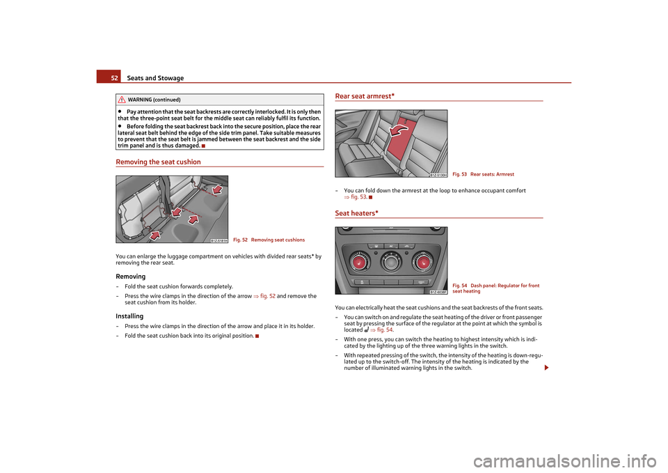
fig. 53 .Seat heaters*You can electrically heat the seat cushions and the seat backrests of the front seats.
– You can switch on and regulate the seat heating of the driver or front passenger seat by pressing the surface of the regulator at the point at which the symbol is
located
fig. 54 .
– With one press, you can switch the heating to highest intensity which is indi- cated by the lighting up of the three warning lights in the switch.
– With repeated pressing of the switch, th e intensity of the heating is down-regu-
lated up to the switch-off. The intensit y of the heating is indicated by the
number of illuminated warning lights in the switch.
WARNING (continued)
Fig. 52 Removing seat cushions
Fig. 53 Rear seats: ArmrestFig. 54 Dash panel: Regulator for front
seat heating
s2lk.2.book Page 52 Monday, April 18, 2011 7:41 AM
Page 54 of 183
Seats and Stowage53
Using the system
Safety
Driving Tips
General Maintenance
Breakdown assistance
Technical Data
WARNING
If you or the passenger have a subdued pa in and/or temperature sensitivity, e.g.
through medication, paralysis or because of chronic illness (e.g. diabetes), we
recommend not to use the seat heating at al l. This can lead to burns on the back,
the posterior and the legs which are difficult to heal. If the seat heating is used,
we recommend to make regular breaks in your journey when driving long
distances, so that in specific cases as mentioned above the body can recuperate
from the stress of the journey. Please consult your doctor, who can evaluate
your specific condition.
Caution
•
You should not kneel on the seats or otherwise apply pressure at specific points
in order to avoid damaging the heating elements of the seat heaters.
•
Do not use the seat heating if the seats are not occupied by persons or if objects
are fastened or stored on them, for example a child seat, a bag etc. A fault of the
heating elements in the seat heating can occur.
•
Do not clean the seats moist page 125.Note
•
The seat heating should only be switched on when the engine is running. This
has a significant effect of saving on the battery capacity.
•
If the on-board voltage drops, the seat heating is switched off automatically, in
order to provide sufficient electrical energy for the engine control.
PedalsConcerning a secure depressing of the peda l, you should use only footmats from the
Škoda genuine accessories.
Operation of the pedals must not be hindered!
WARNING
•
Greater pedal distances may be needed when there is a fault in the brake
system.
•
Do not place any footmats or other additional floor coverings in the area of
the pedals in order to ensure that all the pedals can be fully depressed and are
able to return unobstructed to their initial position - risk of accident!
•
There must be no objects on the floor which could roll under the pedals. You
would then no longer be able to apply the brakes, operate the clutch or acceler-
ator - risk of accident!
luggage compartmentLoading the luggage compartmentPlease observe the following in the interest of having good handling characteristics
of your vehicle:
– Distribute the items of luggage as evenly as possible.
– Place heavy objects as far forward as possible.
– Attach the items of luggage to the lashing eyes or the fixing net* page 54.
In the event of an accident, there is such a high kinetic energy which is produced by
small and light objects that they can cause severe injuries. The magnitude of the
kinetic energy depends on the speed at which the vehicle is travelling and on the
weight of the object. The speed at which the vehicle is travelling is in this case the
more significant factor.
Example: In the event of a frontal collis ion at a speed of 50 km/h, an unsecured
object with a weight of 4.5 kg produces an energy, which corresponds to 20 times
its own weight. This means that it results in a weight of approx. 90 kg. You can
imagine the injuries that can occur, if this “bullet” is flying through the interior
compartment and hits an occupant.
WARNING
•
Stow the objects in the luggage compartment and attach them to the lashing
eyes.
•
Loose objects in the passenger compar tment can be thrown forward during
a sudden manoeuvre or in case of an ac cident and can injure the occupants or
other oncoming traffic. This risk is still increased, if the objects which are flying
around are hit by a deployed airbag. In this case, the objects which are thrown
back can injure th e occupants - hazard.
•
Please note that the handling properti es of your vehicle may be affected
when transporting heavy objects as a result of the displacement of the centre of
gravity. The speed and style of driv ing must be adjusted accordingly.WARNING (continued)
s2lk.2.book Page 53 Monday, April 18, 2011 7:41 AM
Page 55 of 183
Seats and Stowage
54
•
The items carried in the luggage compartment should be stowed in such a
way that no objects are able to slip fo rward if there are any sudden driving or
braking manoeuvres undert aken - risk of injury!
•
Never drive with the boot lid fully opened or slightly ajar otherwise exhaust
gases may get into the interior of the vehicle - risk of poisoning!
•
On no account exceed the permissible axle loads and the permissible gross
weight of the vehicle - risk of accident!
•
Never transport occupants in the luggage compartment!Caution
Please ensure that the heating elements of the rear window heater are not
damaged as a result of objects sliding in this area.
Note
Tyre pressure must be adjusted to the load page 141.Vehicles of category N1On vehicles of the category N1, which are no t fitted with a protective grille, a binding
device which complies with the standard EN 12195 (1 - 4) must be used for trans-
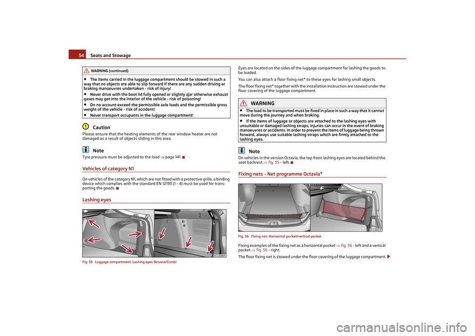
porting the goods.Lashing eyesFig. 55 Luggage compartment: Lashing eyes Octavia/Combi
Eyes are located on the sides of the lugg age compartment for lashing the goods to
be loaded.
You can also attach a floor fixing net* to these eyes for lashing small objects.
The floor fixing net* together with the in stallation instruction are stowed under the
floor covering of the luggage compartment.
WARNING
•
The load to be transported must be fixe d in place in such a way that it cannot
move during the jour ney and when braking.
•
If the items of luggage or objects ar e attached to the lashing eyes with
unsuitable or damaged lashing straps, injuries can occur in the event of braking
manoeuvres or accidents. In order to pr event the items of luggage being thrown
forward, always use suitable lashing st raps which are firmly attached to the
lashing eyes.Note
On vehicles in the version Octavia, the to p front lashing eyes are located behind the
seat backrest fig. 55 - left.Fixing nets - Net programme Octavia*Fig. 56 Fixing net: Horizontal pocket/vertical pocketFixing examples of the fixing net as a horizontal pocket fig. 56 - left and a vertical
pocket fig. 56 - right.
The floor fixing net is stowed under the floor covering of the luggage compartment.
WARNING (continued)
s2lk.2.book Page 54 Monday, April 18, 2011 7:41 AM