service SKODA OCTAVIA TOUR 2011 2.G / (1Z) Owner's Manual
[x] Cancel search | Manufacturer: SKODA, Model Year: 2011, Model line: OCTAVIA TOUR, Model: SKODA OCTAVIA TOUR 2011 2.G / (1Z)Pages: 183, PDF Size: 11.13 MB
Page 3 of 183
Introduction
2
On-board literatureThe on-board literature for your vehicle consists of this ŌĆ£ Owner's
ManualŌĆØ as well as a ŌĆ£ Service scheduleŌĆØ and a ŌĆ£Help on the road ŌĆØ. There
can also be a variety of other additional operating manuals and instruc-
tions on-board (e.g. an operating manual for the radio) depending on the
vehicle model and equipment.
If one of the publications listed above is missing, please contact an
authorised ┼Ākoda dealer immediately, where one will be glad to assist
you in such matters.
One should note that the details given in the vehicle's papers always
take precedence over those in the Owner's Manual.Owner's ManualThis Owner's Manual describes the current scope of equipment. Certain
items of equipment listed are only in stalled later on and only envisaged
for particular markets. The illustrations can differ in minor details from
your vehicle; they are only in tended for general information.
In addition to information regarding all the controls and equipment, the
Owner's Manual also contains important information regarding care and
operation for your safety and also to retain the value of your vehicle. To
provide you with valuable tips an d aids. You will learn how you can
operate your vehicle safely, economically and in an environmentally
conscious way.
For safety reasons, please also pay attention to the information on
accessories, modifications and replacement of parts ’ā×page 146.
The other chapters of the Owner's Manual are also important, however,
for proper treatment of your car - in addition to regular care and mainte-
nance - helps to retain its value and in many cases is also one of the
conditions for possible warranty claims.The Service schedulecontains:
ŌĆó
Vehicle data,
ŌĆó
Service intervals,
ŌĆó
Overview of the service work,
ŌĆó
Service proof,
ŌĆó
Confirmation of mobility warranty (only valid in certain countries),
ŌĆó
important information on the warranty.
The confirmations of the carried out service work are one of the condi-
tions for possible warranty claims.
Please always present the Service schedule when you take your car to an
authorised ┼Ākoda Service Partner.
If the Service schedule is missing or worn, please contact your authorised
┼Ākoda Service Partner, where your car is serviced regularly. You will
receive a duplicate, in which the previously carried out service work are
confirmed.
Help on the roadcontains the most important telephone numbers in individual countries
as well as the addresses and tele phone numbers of ┼Ākoda importers.
s2lk.2.book Page 2 Monday, April 18, 2011 7:41 AM
Page 4 of 183
Contents3
Using the system
Safety
Driving Tips
General Maintenance
Breakdown assistance
Technical Data
ContentsLayout of this Owner's Manual
(explanations)
. . . . . . . . . . . . . . . . . . . . . . . . . .
Using the system
. . . . . . . . . . . . . . . . . . . . .
Cockpit
. . . . . . . . . . . . . . . . . . . . . . . . . . . . . . . . . . . . . . . .
Overview . . . . . . . . . . . . . . . . . . . . . . . . . . . . . . . . . . . .
The brief instruction
. . . . . . . . . . . . . . . . . . . . . . . . . .
Basic functions and important information . . . . .
Instruments and Indicator/Warning Lights
. .
Overview of the instrument cluster . . . . . . . . . . . .
Engine revolutions counter . . . . . . . . . . . . . . . . . . . .
Speedometer . . . . . . . . . . . . . . . . . . . . . . . . . . . . . . . . .
Engine coolant temperature Display . . . . . . . . . . .
Fuel gauge . . . . . . . . . . . . . . . . . . . . . . . . . . . . . . . . . . .
Counter for distance driven . . . . . . . . . . . . . . . . . . .
Service Interval Display . . . . . . . . . . . . . . . . . . . . . . .
Digital clock . . . . . . . . . . . . . . . . . . . . . . . . . . . . . . . . . .
Recommended gear* . . . . . . . . . . . . . . . . . . . . . . . . .
Multi-functional indicator (onboard computer)* .
Warning lights . . . . . . . . . . . . . . . . . . . . . . . . . . . . . . . .
Unlocking and locking
. . . . . . . . . . . . . . . . . . . . . . . .
Key . . . . . . . . . . . . . . . . . . . . . . . . . . . . . . . . . . . . . . . . . .
Changing the battery in the remote control key
Electronic immobiliser . . . . . . . . . . . . . . . . . . . . . . . .
Child safety lock . . . . . . . . . . . . . . . . . . . . . . . . . . . . . .
Central locking system . . . . . . . . . . . . . . . . . . . . . . . .
Remote control* . . . . . . . . . . . . . . . . . . . . . . . . . . . . . .
Synchronisation of the remote control . . . . . . . . .
Anti-theft alarm system* . . . . . . . . . . . . . . . . . . . . . .
Power windows* . . . . . . . . . . . . . . . . . . . . . . . . . . . . .
Lights and Visibility
. . . . . . . . . . . . . . . . . . . . . . . . . . .
Lights . . . . . . . . . . . . . . . . . . . . . . . . . . . . . . . . . . . . . . . .
Interior lighting . . . . . . . . . . . . . . . . . . . . . . . . . . . . . . . Visibility . . . . . . . . . . . . . . . . . . . . . . . . . . . . . . . . . . . . .
Windshield wiper and wash system . . . . . . . . . . . .
Rear-view mirror . . . . . . . . . . . . . . . . . . . . . . . . . . . . .
Seats and Stowage
. . . . . . . . . . . . . . . . . . . . . . . . . . .
Front seats . . . . . . . . . . . . . . . . . . . . . . . . . . . . . . . . . .
Head restraints . . . . . . . . . . . . . . . . . . . . . . . . . . . . . . .
Middle rear head restraint* . . . . . . . . . . . . . . . . . . . .
Rear seats . . . . . . . . . . . . . . . . . . . . . . . . . . . . . . . . . . .
Pedals . . . . . . . . . . . . . . . . . . . . . . . . . . . . . . . . . . . . . . .
luggage compartment . . . . . . . . . . . . . . . . . . . . . . . .
Net partition* (Combi) . . . . . . . . . . . . . . . . . . . . . . . .
The roof rack* . . . . . . . . . . . . . . . . . . . . . . . . . . . . . . . .
Cup holder . . . . . . . . . . . . . . . . . . . . . . . . . . . . . . . . . . .
Note holder . . . . . . . . . . . . . . . . . . . . . . . . . . . . . . . . . .
Ashtray* . . . . . . . . . . . . . . . . . . . . . . . . . . . . . . . . . . . . .
Cigarette lighter*, power sockets . . . . . . . . . . . . . .
Storage compartments . . . . . . . . . . . . . . . . . . . . . . .
Overview . . . . . . . . . . . . . . . . . . . . . . . . . . . . . . . . . . . .
Storage compartment on the front passenger side
Storage compartment on the driver's side . . . . . .
Storage compartment on the dash panel . . . . . . .
Storage compartment in front centre console* .
Storage compartment in the front doors . . . . . . .
Front seat armrest with storage compartment*
Rear seat armrest with storage compartment* .
Storage compartment in re ar centre console* . .
Seat backrest with opening for skis* . . . . . . . . . . .
Clothes hooks* . . . . . . . . . . . . . . . . . . . . . . . . . . . . . . .
Heating and air conditioning system
. . . . . . . .
Air outlet vents . . . . . . . . . . . . . . . . . . . . . . . . . . . . . .
Heating . . . . . . . . . . . . . . . . . . . . . . . . . . . . . . . . . . . . . .
Climatic* . . . . . . . . . . . . . . . . . . . . . . . . . . . . . . . . . . . . .
Starting-off and Driving
. . . . . . . . . . . . . . . . . . . . . .
Setting steering wheel position . . . . . . . . . . . . . . .
Ignition lock . . . . . . . . . . . . . . . . . . . . . . . . . . . . . . . . . . Starting the engine . . . . . . . . . . . . . . . . . . . . . . . . . . .
Switching off the engine . . . . . . . . . . . . . . . . . . . . . .
Shifting . . . . . . . . . . . . . . . . . . . . . . . . . . . . . . . . . . . . . .
Handbrake . . . . . . . . . . . . . . . . . . . . . . . . . . . . . . . . . . .
Rear parking aid* . . . . . . . . . . . . . . . . . . . . . . . . . . . . .
Cruise control system (CCS)* . . . . . . . . . . . . . . . . . .
Communication
. . . . . . . . . . . . . . . . . . . . . . . . . . . . . . .
Mobile phones and two-way radio systems . . . .
Safety
. . . . . . . . . . . . . . . . . . . . . . . . . . . . . . . . . . . . . .
Passive Safety
. . . . . . . . . . . . . . . . . . . . . . . . . . . . . . . .
Basic information . . . . . . . . . . . . . . . . . . . . . . . . . . . .
Correct seated position . . . . . . . . . . . . . . . . . . . . . . .
Seat belts
. . . . . . . . . . . . . . . . . . . . . . . . . . . . . . . . . . . . .
Why seat belts? . . . . . . . . . . . . . . . . . . . . . . . . . . . . . .
The physical principle of a frontal collision . . . . .
Important safety information regarding the use of seat
belts . . . . . . . . . . . . . . . . . . . . . . . . . . . . . . . . . . . . . . . .
How are seat belts correctly fastened? . . . . . . . .
Airbag system
. . . . . . . . . . . . . . . . . . . . . . . . . . . . . . . .
Description of the airbag system . . . . . . . . . . . . . .
Front airbags . . . . . . . . . . . . . . . . . . . . . . . . . . . . . . . .
side airbags* . . . . . . . . . . . . . . . . . . . . . . . . . . . . . . . . .
Head airbags* . . . . . . . . . . . . . . . . . . . . . . . . . . . . . . . .
Deactivating an airbag . . . . . . . . . . . . . . . . . . . . . . . .
Transporting children safely
. . . . . . . . . . . . . . . . .
What you should know about transporting children!
Child seat . . . . . . . . . . . . . . . . . . . . . . . . . . . . . . . . . . . .
Attaching a child seat using the ŌĆ£ISOFIXŌĆØ system
Attaching child seat using the ŌĆ£Top TetherŌĆØ* system
6799101015151516161616171718182129292930303034353637404043
4445484949505051535357585960606061616262626363636464646566666769737373
7475767677778080818181828585858687898990929495979799102103
s2lk.2.book Page 3 Monday, April 18, 2011 7:41 AM
Page 16 of 183
Instruments and Indicator/Warning Lights15
Using the system
Safety
Driving Tips
General Maintenance
Breakdown assistance
Technical Data
Instruments and Indicator/Warning LightsOverview of the instrument cluster
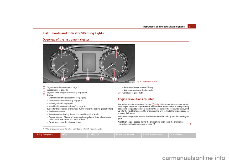
Engine revolutions counter ’ā×page 15
Speedometer ’ā×page 16
Engine coolant temperature display ’ā×page 16
Display
ŌłÆ with counter for distance driven ’ā×page 16
ŌłÆ with Service Interval Display ’ā× page 17
ŌłÆ with digital clock ’ā×page 17
ŌłÆ with Multi-functional indicator* ’ā×page 18
Button for the selection of the mode (t urn button)/the setting (press button):
ŌłÆ Set hours/minutes
ŌłÆ Activating/deactivating the second speed in mph or km/h*
ŌłÆ Service interval - Display of the remaining number of days, kilometres or
miles to the next Inspection Service/Reset*
1)
ŌłÆReset trip counter for distance driven ŌłÆ
Resetting Service Interval Display
ŌłÆ Activate/deactivate display mode
Fuel gauge ’ā×page 16
Engine revolutions counterThe red zone in the revolutions counter ’ā×fig. 15 indicates the maximum permis-
sible engine speed for all gears for an engine which has been run in and operating
at a normal temperature. Before reaching th e red zone of the rev counter scale, shift
up into the next higher gear. The engine control unit restricts the engine speed to
a steady limit value.
Before reaching the red zone of the rev coun ter scale, shift up into the next higher
gear.
Avoid high engine speeds during the driving time and before the engine has
reached operating temperature ’ā×page 111.
Fig. 15 Instrument cluster
1)Valid for countries where the values are indicated in British measuring units.A1A2A3A4A5
A6
A1
s2lk.2.book Page 15 Monday, April 18, 2011 7:41 AM
Page 18 of 183
Instruments and Indicator/Warning Lights17
Using the system
Safety
Driving Tips
General Maintenance
Breakdown assistance
Technical Data
Note
If the display of the second speed is activated in mph or km/h, this speed is shown
instead of the odometer on the display.Service Interval DisplayService Interval Display
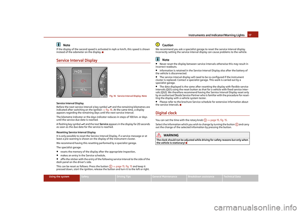
Before the next service interval a key symbol
’üż
and the remaining kilometres are
indicated after switching on the ignition ’ā×fig. 16 . At the same time, a display
appears regarding the remaining days until the next service interval.
The kilometre indicator or the days indicator reduces in steps of 100 km. or days
until the service due date is reached.
A flashing key symbol
’üż
and the text Service appears in the display for 20 seconds
as soon as the due date for the service is reached.
Resetting Service Interval Display
It is only possible to reset the Service In terval Display, if a service message or at
least a pre-warning is shown on the display of the instrument cluster.
We recommend having this resetting performed by a specialist garage.
The specialist garage:
ŌĆó
resets the memory of the display after the appropriate inspection,
ŌĆó
makes an entry in the Service schedule,
ŌĆó
affix the sticker with the entry of the follo wing service interval to the side of the
dash panel on the driver's side.
This can be reset as follows: Press the button ’ā×page 15, fig. 15 and keep it
pressed down, start the ignition, release the button and turn it to the left or right.
Caution
We recommend you ask a specialist garage to reset the service interval display.
Incorrectly setting the service interval display can cause problems to the vehicle.
Note
ŌĆó
Never reset the display between service intervals otherwise this may result in
incorrect readouts.
ŌĆó
information is retained in the Service Interval Display also after the battery of
the vehicle is disconnected.
ŌĆó
The service interval display will need to be re-configured if the instrument
cluster is replaced. Contact a specialist garage. This work is carried out by a
specialist garage.
ŌĆó
The data displayed is the same after rese tting the display with flexible service
intervals (QG1) using the reset button as th at for a vehicle with fixed service inter-
vals (QG2). We therefore recommend having the Service Interval Display reset only
by an authorised ┼Ākoda Service Partner who is familiar with the procedure for reset-
ting the display with a vehicle system tester.
ŌĆó
Please refer to the brochure Service schedule for extensive information about
the service intervals.
Digital clockYou can set the time with the rotary knob ’ā×page 15, fig. 15 .
Select the information which you wish to change by turning the button and carry
out the change of the selected information by pressing the button.
WARNING
The clock should not be adjusted while dr iving for safety reasons but only when
the vehicle is stationary!
Fig. 16 Service Interval Display: NoteA5
A5
A5
s2lk.2.book Page 17 Monday, April 18, 2011 7:41 AM
Page 27 of 183
Instruments and Indicator/Warning Lights
26
If the warning light
’Ćó comes on immediately after starting the engine, the ESP
system can be switched off for technical reasons. In this case, the ESP system can
be switched on again by switching the ignition on and off. If the warning light goes
out, the ESP system is fully functional again.
Further information on the ESP ’ā×page 105, ŌĆ£Electronic stability programme
(ESP)*ŌĆØ.
Electronic Differential Lock (EDL)*
The EDL is a part of the ESP. A fault in the EDL is indicated by the ESP warning light
in the instrument cluster. Have the vehi cle inspected without delay by an author-
ised ┼Ākoda Service Partner. Further information on the EDL ’ā×page 106, ŌĆ£Electronic
Differential Lock (EDL)*ŌĆØ.
Note
If the battery has been disconnected and reconnected, the warning light
’Ćó comes
on after switching on the ignition. The wa rning light must go out after driving a
short distance.
Tyre inflation pressure*
’āć
The warning light
’āć lights up, if there is a substantial drop in inflation pressure in
one of the tyres. Reduce the speed and check or correct as soon as possible the
inflation pressure in the tyres ’ā×page 141.
If the warning light flashes, there is a system fault. Visit the nearest specialist
garage and have the fault rectified.
Further information about tyre pressure-control system ’ā×page 109.
WARNING
ŌĆó
When the warning light
’āć lights up, immediately reduce the speed and
avoid sudden steering and brake manoeu vres. Please stop the vehicle without
delay at the nearest possible stop and inspect the tyres and their inflation pres-
sures.
ŌĆó
Under certain circumstances (e.g. sporty style of driving, wintry or unpaved
roads) the warning light
’āć can be delayed or does not light up at all.
Note
If the battery has been disconnected, the warning light
’āć comes on after switching
on the ignition. The warning light must go out after driving a short distance.
Antilock brake system (ABS)
’ü¬
The warning light
՟ shows the functionality of the ABS.
The warning light comes on for a few seconds after the ignition has been switched
on or when starting the engine. The warning light goes out after an automatic check
sequence has been completed.
A fault in the ABS
The system is not functioning pr operly if the ABS warning light
՟ does not go out
within a few seconds after switching on the ignition, does not light up at all or lights
up while driving. The vehicle will only be braked by the normal brake system. Visit a
specialist garage as quickly as possible an d adjust your style of driving appropriately
as you will not know how great the damage is.
Further information about ABS ’ā×page 108, ŌĆ£Antilock brake system (ABS)ŌĆØ.
A fault in the entire brake system
If the ABS warning light
՟ comes on together with th e brake system warning light
’ü© (handbrake must be released), there is a fault not only in the ABS but also in
another part of the brake system ’ā×.
WARNING
ŌĆó
If the brake system warning light
’ü© comes on together with the ABS
warning light
՟ stop the vehicle immediately and check the brake fluid level in
the reservoir ’ā× page 135, ŌĆ£Brake fluidŌĆØ. If the fluid level has dropped below the
MIN marking, do not drive any further - risk of accident! Obtain professional
assistance.
ŌĆó
Pay attention to the following instruct ions before checking the brake fluid
level and opening the bonnet ’ā×page 131, ŌĆ£Working in the engine compart-
mentŌĆØ.
ŌĆó
If the brake fluid is at the correct leve l, the ABS control function has failed.
The rear wheels may then block very ra pidly when braking. In certain circum-
stances, this can result in the rear end of the car breaking away - risk of skidding!
Drive carefully to the nearest specialist garage and have the fault rectified.
Bonnet
’é▒
The warning light
’é▒ comes on if the bonnet is unlocked. If the bonnet unlocks
while driving, the warning light lights up
’é▒ and as a warning an audible signal
sounds.
s2lk.2.book Page 26 Monday, April 18, 2011 7:41 AM
Page 30 of 183
Unlocking and locking29
Using the system
Safety
Driving Tips
General Maintenance
Breakdown assistance
Technical Data
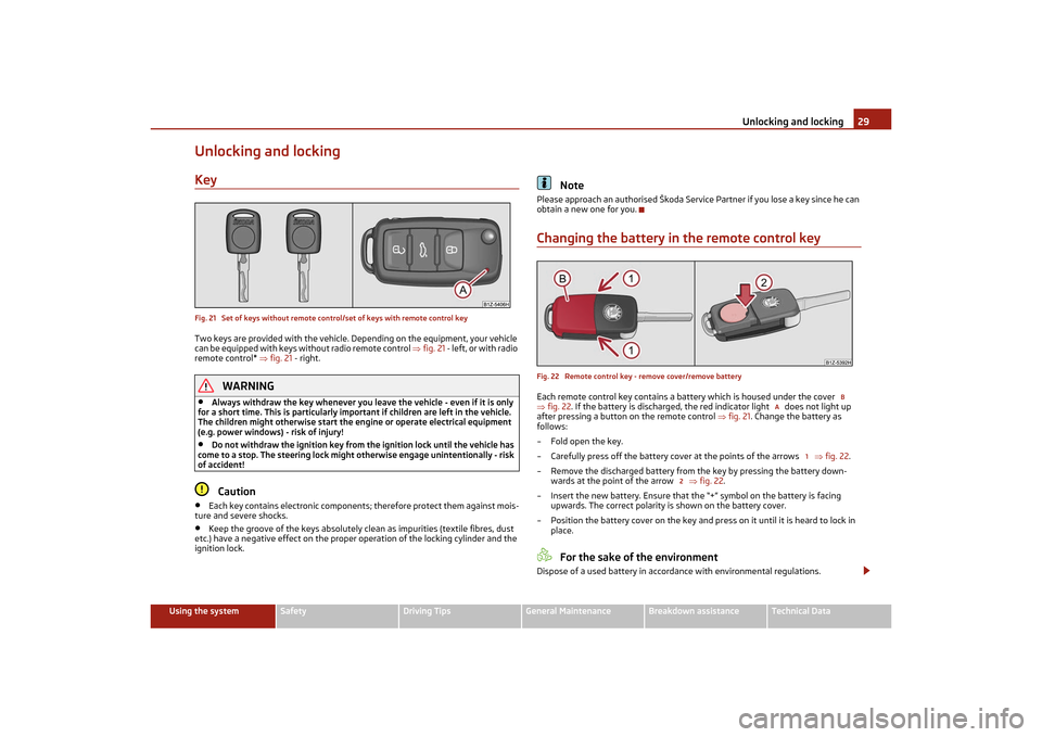
Unlocking and lockingKeyFig. 21 Set of keys without remote control/set of keys with remote control keyTwo keys are provided with the vehicle. Depending on the equipment, your vehicle
can be equipped with keys without radio remote control ’ā×fig. 21 - left, or with radio
remote control* ’ā×fig. 21 - right.
WARNING
ŌĆó
Always withdraw the key whenever you leave the vehicle - even if it is only
for a short time. This is particularly import ant if children are left in the vehicle.
The children might otherwise start the en gine or operate electrical equipment
(e.g. power windows) - risk of injury!
ŌĆó
Do not withdraw the ignition key from the ignition lock until the vehicle has
come to a stop. The steering lock might otherwise engage unintentionally - risk
of accident!Caution
ŌĆó
Each key contains electronic components; therefore protect them against mois-
ture and severe shocks.
ŌĆó
Keep the groove of the keys absolutely clean as impurities (textile fibres, dust
etc.) have a negative effect on the proper operation of the locking cylinder and the
ignition lock.
Note
Please approach an authoris ed ┼Ākoda Service Partner if you lose a key since he can
obtain a new one for you.Changing the battery in the remote control keyFig. 22 Remote control key - remove cover/remove batteryEach remote control key contains a battery which is housed under the cover
’ā× fig. 22 . If the battery is discharged, the red indicator light does not light up
after pressing a button on the remote control ’ā×fig. 21 . Change the battery as
follows:
ŌĆō Fold open the key.
ŌĆō Carefully press off the battery cove r at the points of the arrows ’ā×fig. 22 .
ŌĆō Remove the discharged battery from the key by pressing the battery down- wards at the point of the arrow ’ā×fig. 22 .
ŌĆō Insert the new battery. Ensure that th e ŌĆ£+ŌĆØ symbol on the battery is facing
upwards. The correct polarity is shown on the battery cover.
ŌĆō Position the battery cover on the key and pr ess on it until it is heard to lock in
place.
For the sake of the environment
Dispose of a used battery in accord ance with environmental regulations.
B
A
1
2
s2lk.2.book Page 29 Monday, April 18, 2011 7:41 AM
Page 32 of 183
Unlocking and locking31
Using the system
Safety
Driving Tips
General Maintenance
Breakdown assistance
Technical Data
If the indicator light first of all flashes fast
for about 2 seconds, afterwards lights up
for about 30 seconds and then flashes slowly, there is a fault in the system of the
central locking or the interior monitor* ’ā×page 36. Visit a specialist garage to obtain
assistance.
Convenience operation of the windows*
One can open and close the electrically powered windows when unlocking and
locking the vehicle ’ā×page 39.
Opening a single door*
This function makes it poss ible to only unlock the driver's door. The other doors
remain locked and are only unlocked when the command is repeated.
If you wish, you can have your authorised ┼Ākoda Service Partner activate the func-
tion of the single door opening mode.
Automatic unlocking and locking*
All the doors and the boot lid are locked automatically once the car reaches a speed
of about 15 km/h.
If the ignition key is withdrawn, the car is then automatically unlocked again. In
addition, it is possible for the driver to unlock the car by pressing the central locking
button
’üé or by pulling the door opening lever.
If you wish, you can have a specialist gara ge activate the automatic locking function.WARNING
Locking the doors prevents involuntary opening in an exceptional situation (an
accident). Locked doors prevent unwanted entry into the vehicle from outside,
for example at road crossings. Locked do ors do, however, make it more difficult
for rescuers to get into the vehicl e in an emergency - danger to life!
Note
ŌĆó
In the event of an accident in which the airbags are deployed, the locked doors
are automatically unlocked in order to enable rescuers to gain access to the vehicle.
ŌĆó
Only the front doors can be unlocked and locked using the key if the central
locking system fails. You can lock or unlo ck manually the other doors and the boot
lid.
ŌłÆEmergency locking of the door ’ā×page 33.
ŌłÆ Emergency unlocking of the boot lid ’ā×page 34.
Safe securingThe central locking system is equipped with a safe securing
2) system. Locking the
vehicle from the outside causes the door lock s to be automatically blocked. It is not
possible to open the doors with the door handle either from the inside or from the
outside. This acts as an effective deterren t for attempts to break into your vehicle.
You can deactivate the safe securing system by locking twice within 2 seconds.
If the safe securing system is not operat ing, the warning light in the driver door
flashes for about 2 seconds fast, goes out and starts to flash slowly again after
about 30┬░seconds.
The safe securing system is again activate d the next time the vehicle is unlocked
and locked again.
The doors can be opened from the inside if the vehicle is locked and the safe
securing system is deactivated:
ŌĆó
The door is unlocked by actu ating the door-opening lever.
ŌĆó
The door opens upon actuating the door-opening lever again.
WARNING
If the vehicle is locked from the outsid e and the safe securing system is acti-
vated, there must not be any person and animals in the vehicle as it is then not
possible to open either a door or a window from the inside. The locked doors
make it more difficult for rescuers to get into the vehicle in an emergency -
hazard!
Note
The anti-theft alarm system* is also acti vated with the deactivated safe securing
system when locking the vehicle. The interior monitor* is however not activated.2)Only valid for some countries.
s2lk.2.book Page 31 Monday, April 18, 2011 7:41 AM
Page 36 of 183
Unlocking and locking35
Using the system
Safety
Driving Tips
General Maintenance
Breakdown assistance
Technical Data
If a lost key is replaced or if the receiver unit has been repaired or a new unit
installed, it is then necessary for an auth
orised ┼Ākoda Service Partner to initialise
the system. Only after this is it poss ible to again use the remote control.
Note
ŌĆó
The remote control is automatically deactivated when the ignition is switched
on.
ŌĆó
The operation of the remote control may temporarily be affected by interfer-
ence from transmitters close to the car and which operate in the same frequency
range (e.g. mobile phone, TV transmitter).
ŌĆó
The battery must be replaced, ideally by an authorised ┼Ākoda Service Partner, if
the central locking or anti-theft alarm syst em does react to the remote control at
less than 3 metres away.
ŌĆó
If the driver door is opened, the vehicle cannot be locked using the remote
control.
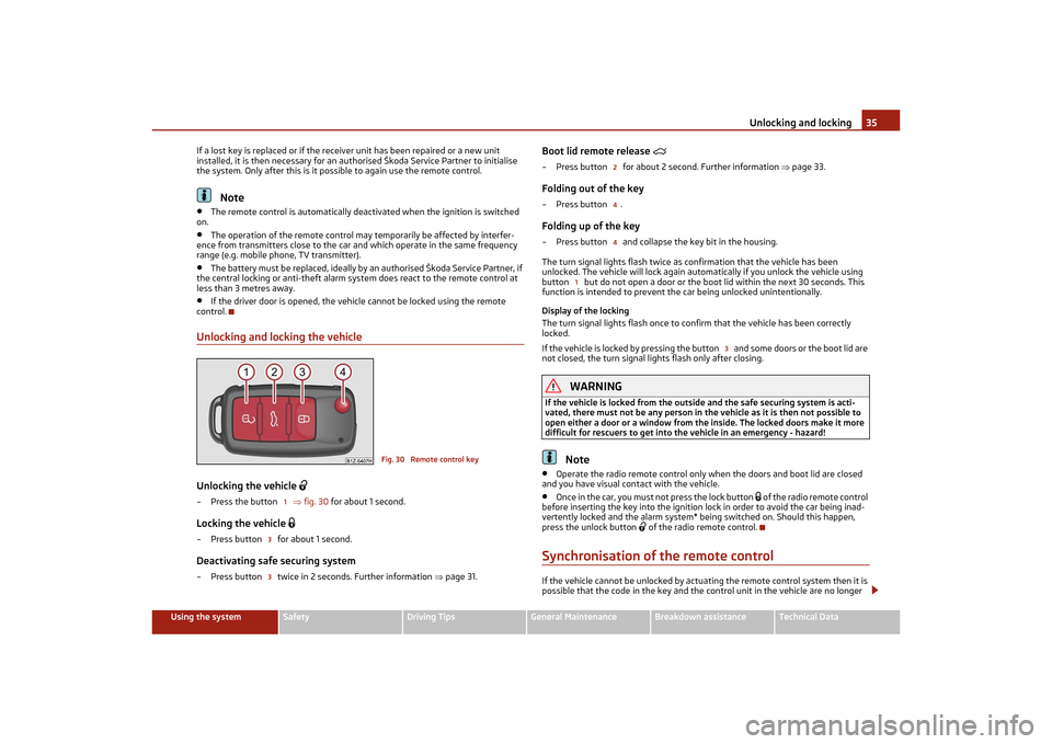
Unlocking and locking the vehicleUnlocking the vehicle
’ü¢
ŌĆō Press the button ’ā×fig. 30 for about 1 second.Locking the vehicle
’üŚ
ŌĆō Press button for about 1 second.Deactivating safe securing systemŌĆō Press button twice in 2 seconds. Further information ’ā×page 31.
Boot lid remote release
’é▓
ŌĆō Press button for about 2 second. Further information ’ā×page 33.Folding out of the keyŌĆōPress button .Folding up of the keyŌĆō Press button and collapse the key bit in the housing.
The turn signal lights flash twice as confirmation that the vehicle has been
unlocked. The vehicle will lock again automatically if you unlock the vehicle using
button but do not open a door or the b oot lid within the next 30 seconds. This
function is intended to prevent th e car being unlocked unintentionally.
Display of the locking
The turn signal lights flash once to co nfirm that the vehicle has been correctly
locked.
If the vehicle is locked by pressing the button and some doors or the boot lid are
not closed, the turn signal li ghts flash only after closing.
WARNING
If the vehicle is locked from the outsid e and the safe securing system is acti-
vated, there must not be any person in th e vehicle as it is then not possible to
open either a door or a window from the inside. The locked doors make it more
difficult for rescuers to get into the vehicle in an emergency - hazard!
Note
ŌĆó
Operate the radio remote control only when the doors and boot lid are closed
and you have visual contact with the vehicle.
ŌĆó
Once in the car, you must not press the lock button
’üŚ of the radio remote control
before inserting the key into the ignition lock in order to avoid the car being inad-
vertently locked and the alarm system* being switched on. Should this happen,
press the unlock button
’ü¢ of the radio remote control.
Synchronisation of the remote controlIf the vehicle cannot be unlocked by actuating the remote control system then it is
possible that the code in the key and the control unit in the vehicle are no longer
Fig. 30 Remote control key
1
33
244
1
3
s2lk.2.book Page 35 Monday, April 18, 2011 7:41 AM
Page 47 of 183
Lights and Visibility
46
Automatic wipe/wash for windscreen
ŌĆō Pull the lever towards the steering wheel into sprung position , the wash system sprays immediately, the windscreen wiper starts wiping a little later. The
wash system and the windscreen wiper operate simultaneously at a speed of
more than 120 km/h.
ŌĆō Release the lever. The windscreen wash system stops and the wiper continues for another 3 - 4 wiper strokes (depending on the period of spraying of the wind-
screen). At a speed of more than 2 km/h, the wiper wipes once again* 5 seconds
after the last wiper stroke in order to wipe the last drops from the windscreen.
This function can be activated/de activated by a specialist garage.Wiping the rear window pane*ŌĆō Push the lever away from the steering wheel into position - the widescreen
wiper will operate every 6 seconds.Automatic wipe/wash for the rear window pane*ŌĆō Press the lever from the steering wheel forward into the sprung position , the
wash system sprays immediately, the windscreen wiper starts wiping a little
later. As long as you hold the lever in this position, the wiper operates as well as
the wash system.
ŌĆō Letting go of the lever will cause the windscreen wash system to stop and the wiper to continue for another 2 - 3 wiper strokes (depending on the period of
spraying of the windscreen). The lever will stay in position after releasing it .Switching windscreen wipers offŌĆō Move the lever back into its home position .
After the windscreen wiper switches off each time or the ignition switches off for
the third time, the position of the windscreen wiper changes, this counteracts an
early fatigue of the wiper rubbers.
The windscreen wipers and the wash system only operate if the ignition is switched
on and the bonnet is closed
4).
If the intermittent wipe is switched on, the intervals are also controlled depending
on speed.
The rear window will be wiped again if the front window wipers are on when
reverse gear is selected. The windscreen washer nozzles are heated* when the ignition is switched on.
Top up with wash liquid
’ā×page 140.
Winter position
If the windscreen wipers are in rest position, they cannot be folded out from the
windscreen. For this reason we recommend adjusting the windscreen wipers in
winter so that they can be folded out from the windscreen easily. You can set this
rest position as follows:
ŌĆó
Switch on the windscreen wipers.
ŌĆó
Switch off the ignition. The windscreen wipers remain in the position in which
they were when switching off the ignition.
You can also use the service position ’ā×page 47 as a winter position.
WARNING
ŌĆó
Properly maintained windscreen wiper bl ades are essential for clear visibility
and safe driving ’ā×page 47.
ŌĆó
Do not use the windscreen washer system at low temperatures, without
heating the windscreen beforehand. Ot herwise the window cleaner could
freeze on the windscreen and restrict the view to the front.
ŌĆó
The rain sensor only operates as a supp ort. The driver is not released from
the responsibility to set the function of the windscreen wipers manually
depending on the visibility conditions.Caution
In frosty weather, please first of all check whether the windscreen wiper blades are
not frozen to the windscreen before switching them on. Switching on windscreen
wipers when the blades are frozen to the windscreen may result in damage both to
the blades and the motor of the windscreen wipers!
Note
ŌĆó
If the slower or the faster wiper setting is switched on ’ā×page 45, fig. 43
and the vehicle speed decreases to below 4 km/h, the lower wiper step is switched
on automatically. At a speed increase of more than 8 km/h the previous wiper
setting is established again.
ŌĆó
If there is an obstacle on the windscreen, the wiper will try to push away the
obstacle. If the obstacle continues to bloc k the wiper, the wiper stops after 5 cycles,
in order to avoid a damage to the wiper. Remove the obstacle and switch on the
wiper again.
4)On vehicles which do not have a contact switch for the bonnet, the windshield wiper and wash
system operates also when the bonnet is opened.
5
6
7
6
0
2
3
s2lk.2.book Page 46 Monday, April 18, 2011 7:41 AM
Page 48 of 183
Lights and Visibility47
Using the system
Safety
Driving Tips
General Maintenance
Breakdown assistance
Technical Data
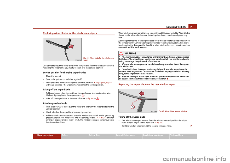
Replacing wiper blades for the windscreen wipersOne cannot fold out the wiper arms in the rest position from the windscreen. Before
replacing the wiper arms you must put them into the service position.Service position for changing wiper bladesŌĆō Close the bonnet.
ŌĆō Switch the ignition on and then again off.
ŌĆō Then press the windscreen wiper lever in the position ’ā×page 45, fig. 43
within 20 seconds - the wiper arms move into the service position.Taking off the wiper bladeŌĆō Fold windscreen wiper arm out from th e windscreen and position the wiper
blade at right angles to the wiper arm ’ā×.
ŌĆō Take off the wiper blade in direction of arrow ’ā×fig. 44 ’ā× .Attaching a wiper bladeŌĆō Push the new wiper blade over the wiper arm and turn the wiper blade into the
vertical position.
ŌĆō Check whether the wiper blade is correctly attached.
ŌĆō Fold the windscreen wiper arms onto the window and switch on the ignition. By
pressing the window wiper lever into the sprung position ’ā×fig. 44 or when
driving at a speed greater than 4 km/h, the windscreen wiper arms move back
into the rest position. Wiper blades in proper condition are essential to obtain good visibility. Wiper blades
should not be allowed to become dirtied by dust, insect remains and preserving
wax.
Juddering or smearing of the wiper blades could then be due to wax residues left on
the windscreen by vehicle washing in automatic vehicle wash systems. It is there-
fore important to degrease
the lips of the wiper blades after every pass through an
automatic vehicle wash system .
WARNING
ŌĆó
The ignition must not be switched on if the front windscreen wiper arms are
folded out. The wiper blades would move back into their rest position and while
doing so damage the paintwork of the bonnet.
ŌĆó
If the windscreen wipers are handled care lessly, there is a risk of damage to
the windscreen.
ŌĆó
You should clean the wiper blades regu larly with a windscreen cleaner in
order to avoid any smears. Clean a wiper blad e with a sponge or cloth if it is very
dirty, for example from insect residues.
ŌĆó
Replace the wiper blades once or twice a year for safety reasons. These can
be bought from an authorised ┼Ākoda Service Partner.
Replacing the wiper blade on the rear window wiperTaking off the wiper blade ŌĆō Fold windscreen wiper arm out from the windscreen and position the wiper
blade at right angles to the wiper arm ’ā×fig. 45 .
ŌĆō Hold the window wiper arm at the top end with one hand.
Fig. 44 Wiper blade for the windscreen
wiper
4
4
Fig. 45 Wiper blade for rear window
s2lk.2.book Page 47 Monday, April 18, 2011 7:41 AM