boot SKODA RAPID 2012 1.G User Guide
[x] Cancel search | Manufacturer: SKODA, Model Year: 2012, Model line: RAPID, Model: SKODA RAPID 2012 1.GPages: 180, PDF Size: 4.36 MB
Page 33 of 180

Opening/closing
Fig. 15
Opening the boot lid
First read and observe the introductory information and safety warn-
ings on page 30.
After unlocking the vehicle, you can open the lid by pushing the handle located
above the licence plate.
Opening
›
Push the handle and lift the boot lid in the direction of the arrow
» Fig. 15.
Closing
› Pull down the boot lid and close it with a slight swing.
A handle which makes the closing easier is located on the inner panelling of the
boot lid. ÐAutomatic locking
First read and observe the introductory information and safety warn-
ings on page 30.
If the vehicle was locked with the button
on the remote control key before the
boot lid was closed, the lid is automatically locked as soon as it is closed.
The delayed automatic locking function of the boot lid can be activated on your
vehicle. The following applies following activation of this function: If the boot lid
was locked with the button on the remote control key 2
» page 28, then it is
possible to open the lid within a limited period of it being closed.
If you wish, a
ŠKODA Service Partner can activate or deactivate the delayed auto-
matic locking of the boot lid. The Service Partner will also provide any further in-
formation that is required.
ä
ä There is a risk of unwanted entry into the vehicle before the boot lid is locked au-
tomatically. Always lock the vehicle using the button on the remote control or
with the key if no remote control is available » page 27 .Ð Emergency unlocking
Fig. 16
Emergency unlocking of the boot
lid
First read and observe the introductory information and safety warn-
ings on page 30.
The boot lid can be unlocked manually if there is a fault in the central locking sys-
tem.
Unlocking
›
Fold the rear seat backrest forward
» page 47, Rear seats.
› Insert the vehicle key into the slot in the trim panel as far as the stop.
› Unlock the lid by moving it in the direction of the arrow.
› Open the boot lid. Ð Electrical power windows
ä
Introduction
This chapter contains information on the following subjects:
Opening/closing the windows 32
£
ä
31
Unlocking and locking
Page 38 of 180

Headlamp range adjustment
Fig. 20
Dash panel: Lights and visibility
First read and observe the introductory information and safety warn-
ings on page 34.
›
Turn the control dial
» Fig. 20 to the desired width of illumination.
Settings
The positions correspond approximately to the following car load. Front seats occupied, boot empty.
All seats occupied, boot empty.
All seats occupied, boot loaded.
Driver seat occupied, boot loaded. CAUTION
Always adjust the headlight range adjustment in such a way that:
■ it does not dazzle other road users, especially oncoming traffic;
■ and the range is sufficient for safe driving. Note
We recommend you adjust the headlight beam when the low beam is switched
on. Ð
ä -
1
2
3 Turn signal and main beam lever
Fig. 21
Turn signal and main beam lever
First read and observe the introductory information and safety warn-
ings on page 34.
The parking light and headlight flasher are also operated with the turn signal and
main beam lever.
Right and left turn signal light
› Push the lever
» Fig. 21 upwards A
or downwards B
.
› If you only wish to flash three times (the "convenience turn signal"), briefly
push the lever to the upper or lower pressure point and release again.
› Turn signal for changing lanes – to only flash briefly, move the lever up or down
to the pressure point and hold it in this position.
Main beam
› Switch on the low beam » page 34
.
› Press the lever
» Fig. 21 in the direction of arrow C
.
› The main beam is switched off by pulling the lever into the initial position in the
direction of arrow D
.
Headlight flasher
› Pull the lever
» Fig. 21 towards the steering wheel (spring-tensioned position)
in the direction of the arrow D
.
Parking light
Description of the operation » page 37 CAUTION
Only use the main beam or the headlight flasher if other road users will not be
dazzled. £
ä
36 Using the system
Page 50 of 180
WARNING
■ The belts and the belt locks must be in their original position after folding
back the seat backrests – they must be ready to use.
■ The seat backrests must be securely interlocked in position so that no ob-
jects in the boot can slide into the passenger compartment if there is sudden
braking – risk of injury. ■ Ensure that the rear seat backrests are properly engaged. Only then can the
seat belt for the middle seat reliably fulfil its function. CAUTION
Ensure that the seat belts are not damaged when operating the seat backrests.
Under no circumstances must the seat belts be jammed by the folded back seat
backrests. ÐRear armrest
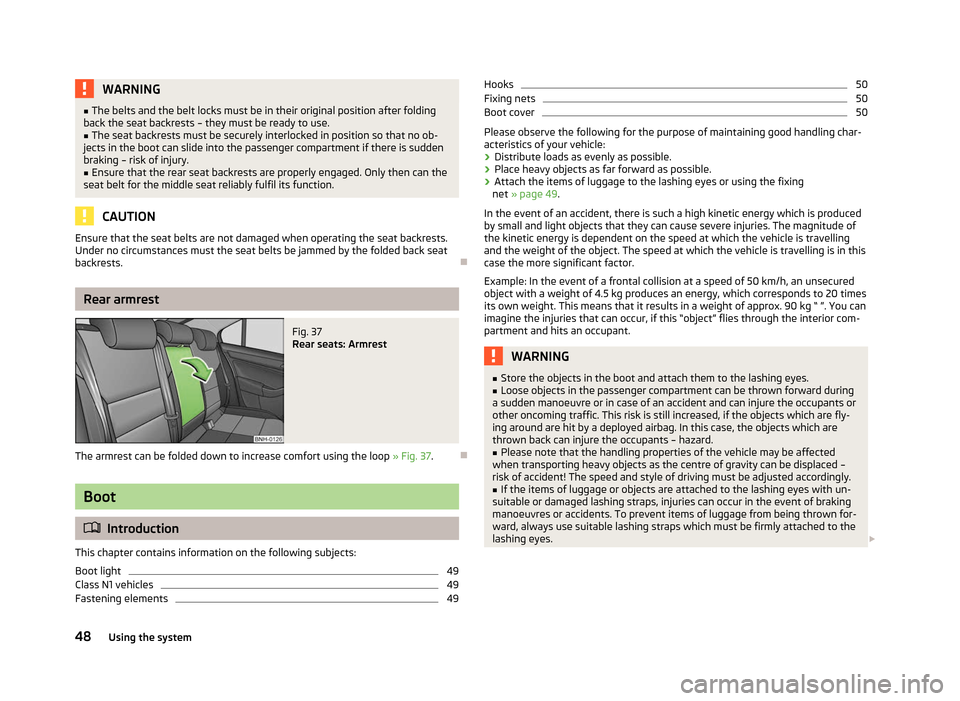
Fig. 37
Rear seats: Armrest
The armrest can be folded down to increase comfort using the loop » Fig. 37.Ð Boot
ä
Introduction
This chapter contains information on the following subjects:
Boot light 49
Class N1 vehicles 49
Fastening elements 49Hooks 50
Fixing nets 50
Boot cover 50
Please observe the following for the purpose of maintaining good handling char-
acteristics of your vehicle:
› Distribute loads as evenly as possible.
› Place heavy objects as far forward as possible.
› Attach the items of luggage to the lashing eyes or using the fixing
net » page 49 .
In the event of an accident, there is such a high kinetic energy which is produced
by small and light objects that they can cause severe injuries. The magnitude of
the kinetic energy is dependent on the speed at which the vehicle is travelling
and the weight of the object. The speed at which the vehicle is travelling is in this
case the more significant factor.
Example: In the event of a frontal collision at a speed of 50 km/h, an unsecured
object with a weight of 4.5 kg produces an energy, which corresponds to 20 times
its own weight. This means that it results in a weight of approx. 90 kg “ ”. You can
imagine the injuries that can occur, if this “object” flies through the interior com-
partment and hits an occupant. WARNING
■ Store the objects in the boot and attach them to the lashing eyes.
■ Loose objects in the passenger compartment can be thrown forward during
a sudden manoeuvre or in case of an accident and can injure the occupants or
other oncoming traffic. This risk is still increased, if the objects which are fly-
ing around are hit by a deployed airbag. In this case, the objects which are
thrown back can injure the occupants – hazard.
■ Please note that the handling properties of the vehicle may be affected
when transporting heavy objects as the centre of gravity can be displaced –
risk of accident! The speed and style of driving must be adjusted accordingly. ■ If the items of luggage or objects are attached to the lashing eyes with un-
suitable or damaged lashing straps, injuries can occur in the event of braking
manoeuvres or accidents. To prevent items of luggage from being thrown for-
ward, always use suitable lashing straps which must be firmly attached to the
lashing eyes. £
48 Using the system
Page 51 of 180
WARNING (Continued)
■ The items carried in the boot must be stored in such a way that no objects
are able to slip forward if any sudden driving or braking manoeuvres are un-
dertaken – risk of injury!
■ When transporting fastened objects which are sharp and dangerous in the
boot that has been enlarged by folding the rear seats forward, ensure the
safety of the passengers transported on the other rear seats » page 93, Cor-
rect seated position for the occupants on the rear seats .
■ If the rear seat next to the folded forward seat is occupied, ensure maxi-
mum safety, e.g. by placing the goods to be transported in such a way that the
seat is prevented from folding back in case of a rear collision.
■ Never drive with the boot lid fully opened or slightly ajar otherwise exhaust
gases may get into the interior of the vehicle – risk of poisoning!
■ Under no circumstances, should the permissible axle loads and permissible
gross weight of the vehicle be exceeded – risk of accident! ■ Never transport people in the boot! CAUTION
Please ensure that the heating elements for the rear window heater are not dam-
aged as a result of abrasive objects. Note
Tyre pressure must be adjusted to the load » page 138, Service life of tyres .Ð Boot light
First read and observe the introductory information and safety warn-
ings on page 48.
The light comes on automatically when the boot lid is opened. If the lid remains
open for more than about 10
minutes, the boot light switches off automatically. ÐClass N1 vehicles
First read and observe the introductory information and safety warn-
ings on page 48.ä
ä On class N1 vehicles, which are not fitted with a protective grille, a lashing set
which complies with the standard EN
12195 (1 - 4) must be used for fastening the
load. Ð Fastening elements
Fig. 38
Boot: Lashing eyes and fasten-
ing elements
First read and observe the introductory information and safety warn-
ings on page 48.
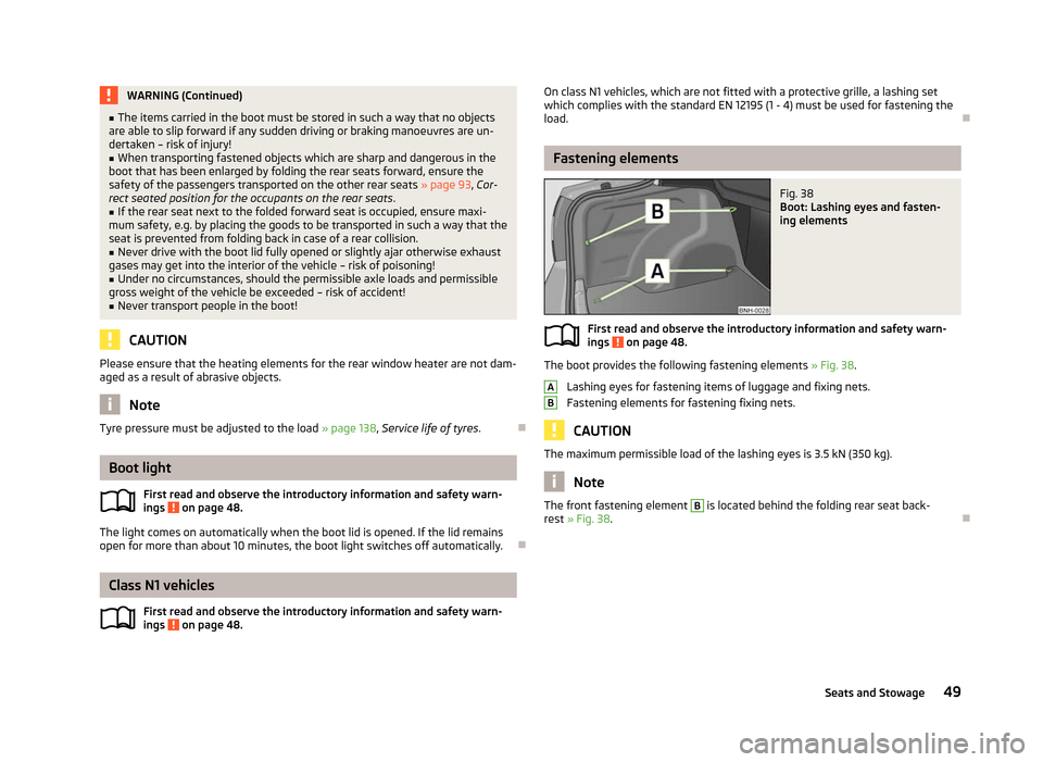
The boot provides the following fastening elements
»
Fig. 38.
Lashing eyes for fastening items of luggage and fixing nets.
Fastening elements for fastening fixing nets. CAUTION
The maximum permissible load of the lashing eyes is 3.5 kN (350 kg). Note
The front fastening element B
is located behind the folding rear seat back-
rest » Fig. 38. Ð
ä A
B
49
Seats and Stowage
Page 52 of 180
Hooks
Fig. 39
Boot: Hooks
First read and observe the introductory information and safety warn-
ings on page 48.
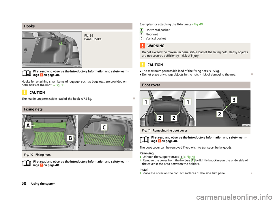
Hooks for attaching small items of luggage, such as bags etc., are provided on
both sides of the boot. » Fig. 39.
CAUTION
The maximum permissible load of the hook is 7.5 kg. ÐFixing nets
Fig. 40
Fixing nets
First read and observe the introductory information and safety warn-
ings on page 48.ä
ä Examples for attaching the fixing nets
» Fig. 40.
Horizontal pocket
Floor net
Vertical pocket WARNING
Do not exceed the maximum permissible load of the fixing nets. Heavy objects
are not secured sufficiently – risk of injury! CAUTION
■ The maximum permissible load of the fixing nets is 1.5 kg.
■ Do not place any sharp objects in the nets – risk of damaging the net. Ð Boot cover
Fig. 41
Removing the boot cover
First read and observe the introductory information and safety warn-
ings on page 48.
The boot cover can be removed if you wish to transport bulky goods.
Removing
›
Unhook the support straps 1
» Fig. 41.
› Remove the cover from the holders 2
by lightly knocking on the underside of
the cover in the area between the holders.
Install
› Place the cover on the contact surfaces of the side trim panel.
£ A
B
C
ä
50 Using the system
Page 53 of 180
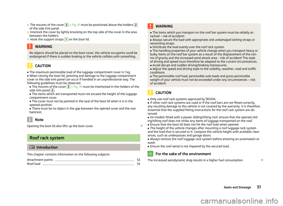
›
The mounts of the cover 3
» Fig. 41 must be positioned above the holders 2
of the side trim panel.
› Interlock the cover by lightly knocking on the top side of the cover in the area
between the holders.
› Hook the support straps 1
on the boot lid.
WARNING
No objects should be placed on the boot cover, the vehicle occupants could be
endangered if there is sudden braking or the vehicle collides with something. CAUTION
■ The maximum permissible load of the luggage compartment cover is 1 kg.
■ When closing the boot lid, jamming and damage to the luggage compartment
cover or the side trim panel can occur if handled in an unprofessional way. The
following guidelines must be observed. ■ The mounts of the cover 3
» Fig. 41 must be interlocked in the holders of the
side trim panel 2
.
■ The items which are transported must not exceed the height of the luggage
compartment cover. ■ The cover must not be jammed in the seal of the boot lid when it is in the
opened position.
■ There must be no object in the gap between the opened cover and the rear
backrest. Note
Opening the boot lid also lifts up the boot cover. ÐRoof rack system
ä
Introduction
This chapter contains information on the following subjects:
Attachment points 52
Roof load 52 WARNING
■ The items which you transport on the roof bar system must be reliably at-
tached – risk of accident!
■ Always secure the load with appropriate and undamaged lashing straps or
tensioning straps.
■ Distribute the load evenly over the roof rack system.
■ The handling properties of your vehicle change when you transport heavy or
bulky items on the roof bar system as a result of the displacement of the cen-
tre of gravity and the increased wind attack area – risk of accident! The style
of driving and speed must therefore be adapted to the current circumstances. ■ Avoid abrupt and sudden driving/braking manoeuvres.
■ Adjust the speed and driving style to the visibility, weather, road and traffic
conditions. ■ The permissible roof load, permissible axle loads and gross permissible
weight of your vehicle must not be exceeded under any circumstances – risk
of accident! CAUTION
■ Only use roof rack systems approved by
ŠKODA.
■ If other roof rack systems are used or if the roof bars are not fitted correctly,
any resulting damage to the vehicle is not covered by the warranty. It is therefore
essential that the supplied fitting instructions for the roof rack system are ob-
served.
■ On models fitted with a power sliding/tilting roof, ensure that the opened slid-
ing/tilting roof does not strike any items of luggage transported on the roof. ■ Ensure that the boot lid does not hit the roof load when opened.
■ The height of the vehicle changes after mounting a roof luggage rack system
and the load that is secured to it. Compare the vehicle height with available clear-
ances, such as underpasses and garage doors.
■ Always remove the roof luggage rack system before entering an automated car
wash. ■ Ensure the roof aerial is not impaired by the secured load. For the sake of the environment
The increased aerodynamic drag results in a higher fuel consumption. Ð
51
Seats and Stowage
Page 56 of 180
Note
■ The cigarette lighter socket can also be used as a 12Volt socket for electrical ap-
pliances » page 54, 12-volt power socket.
■ Further information » page 144, Accessories, changes and replacement of
parts. Ð12-volt power socket
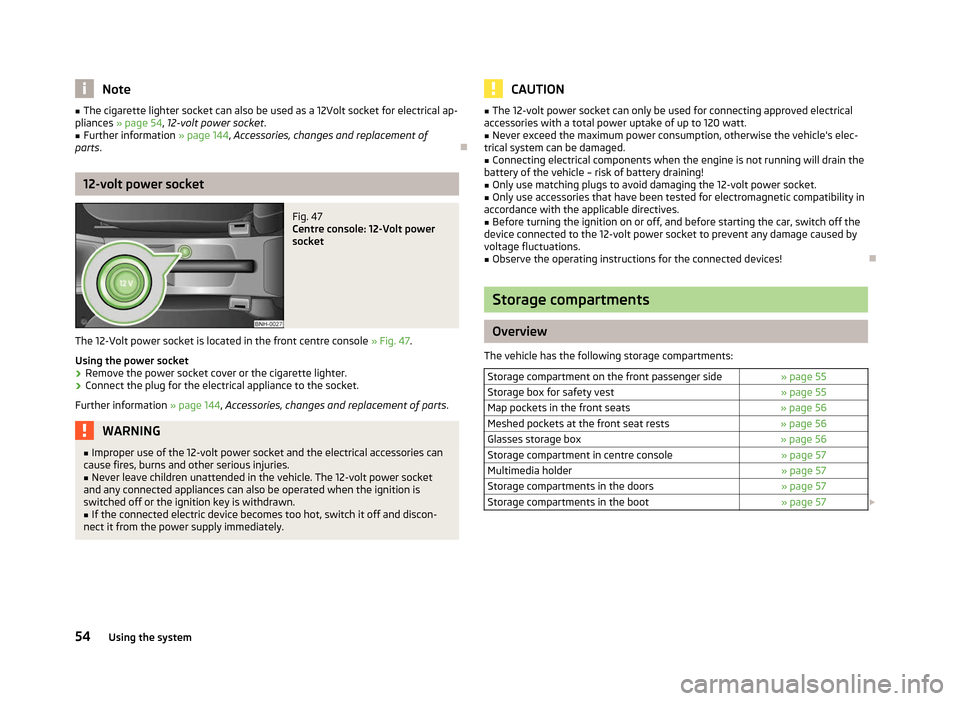
Fig. 47
Centre console: 12-Volt power
socket
The 12-Volt power socket is located in the front centre console » Fig. 47.
Using the power socket
› Remove the power socket cover or the cigarette lighter.
› Connect the plug for the electrical appliance to the socket.
Further information » page 144, Accessories, changes and replacement of parts .WARNING
■ Improper use of the 12-volt power socket and the electrical accessories can
cause fires, burns and other serious injuries.
■ Never leave children unattended in the vehicle. The 12-volt power socket
and any connected appliances can also be operated when the ignition is
switched off or the ignition key is withdrawn. ■ If the connected electric device becomes too hot, switch it off and discon-
nect it from the power supply immediately. CAUTION
■ The 12-volt power socket can only be used for connecting approved electrical
accessories with a total power uptake of up to 120
watt.
■ Never exceed the maximum power consumption, otherwise the vehicle's elec-
trical system can be damaged.
■ Connecting electrical components when the engine is not running will drain the
battery of the vehicle – risk of battery draining!
■ Only use matching plugs to avoid damaging the 12-volt power socket.
■ Only use accessories that have been tested for electromagnetic compatibility in
accordance with the applicable directives.
■ Before turning the ignition on or off, and before starting the car, switch off the
device connected to the 12-volt power socket to prevent any damage caused by
voltage fluctuations. ■ Observe the operating instructions for the connected devices! Ð Storage compartments
Overview
The vehicle has the following storage compartments: Storage compartment on the front passenger side » page 55
Storage box for safety vest » page 55
Map pockets in the front seats » page 56
Meshed pockets at the front seat rests » page 56
Glasses storage box » page 56
Storage compartment in centre console » page 57
Multimedia holder » page 57
Storage compartments in the doors » page 57
Storage compartments in the boot » page 57£54
Using the system
Page 59 of 180

Storage compartment in centre console
Fig. 53
Centre console: Storage compartments
Open storage compartment at the front of the centre console.
Open storage compartment at the rear of the centre console. ÐMultimedia holder
Fig. 54
Front centre console: Multimedia
holder
The multimedia holder can be found in the stowage compartment of the front
centre console » Fig. 54.
You can use this holder to store e.g. a mobile phone, MP3 player or similar devi-
ces. WARNING
Never use the multimedia holder as an ashtray or for storing flammable ob-
jects – risk of fire! ÐA
B Storage compartments in the doors
Fig. 55
Storage compartment: in the front door/in the rear door
Storage compartment in the front doors
Bottle compartment in the front doors
Storage compartment in the rear doors
Bottle compartment in the rear doors WARNING
Use the area A
» Fig. 55 of the storage compartment only for storing objects
which do not project so that the effectiveness of the side airbag is not im-
paired. Ð Storage compartments in the boot
Fig. 56
Boot: Stowage compartment
The cover for the side compartment can be removed, thus enlarging the boot. £ A
B
C
D
57
Seats and Stowage
Page 61 of 180
Heating and air conditioning system
Heating and air conditioning system
Introductory information
The heating effect is dependent upon the coolant temperature, thus full heat
output only occurs when the engine has reached its operating temperature.
If the cooling system is switched on, the temperature and air humidity drops in
the vehicle. The well-being of the occupants of the car is enhanced as a result of
this particularly at high outside temperatures and a high air humidity. The system
prevents the windows misting up during the cold season of the year.
It is possible to briefly activate recirculated air mode to enhance the cooling ef-
fect.
The air inlet in front of the windscreen must be free of ice, snow or leaves to en-
sure that the heating and cooling system operates properly.
After switching on the cooling Condensation from the evaporator of the air condi-
tioning may drip down and form a puddle below the vehicle. This is quite normal
and not an indication of a leak! WARNING
■ For your own safety and that of other road users, ensure that all the win-
dows are free of ice, snow and misting. Please familiarize yourself about how
to correctly operate the heating and ventilation systems, how to demist and
defrost the windows, as well as with the cooling mode.
■ Do not leave recirculated air mode on over a longer period of time, as “stale”
air can cause fatigue of the driver and passengers, reduce attention levels and
also cause the windows to mist up. The risk of having an accident increases.
Switch off recirculated air mode as soon as the windows start to mist up. Note
■ The used air streams out through the vents in the boot.
■ We recommend that you do not smoke in the vehicle when the recirculating air
mode is operating since the smoke which is drawn at the evaporator from the in-
terior of the vehicle forms deposits in the evaporator of the air conditioning sys- tem. This produces a permanent odour when the air conditioning system is oper-
ating which can only be eliminated through considerable effort and expense (re-
placement of compressor). ■ To ensure that the heating and air conditioning systems work properly, do not
block up the air outlet vents with any objects. Ð Using the air conditioning system economically
The compressor on the air conditioning system uses power from the engine when
in cooling mode which will effect the fuel consumption.
It recommended to open the windows or the doors of a vehicle for which the inte-
rior has been strongly heated through the effect of direct sunlight in order to al-
low the heated air to escape.
The cooling system should not be switched on while travelling when the window
is open.
If the desired interior temperature can also be achieved without activating the
cooling system, fresh air mode should be selected. For the sake of the environment
Pollutant emissions are also reduced when fuel is saved. Ð Operational problems
If the cooling system does not operate at outside temperatures higher than +5 °C,
there is a problem in the system. The reasons for this may be.
› One of the fuses has blown. Check the fuse and replace if necessa-
ry »
page 156 .
› The cooling system has switched off automatically for a short time because the
coolant temperature of the engine is too hot » page 9.
If you cannot rectify the functional fault yourself, or the cooling capacity decrea-
ses, the cooling system must be switched off. Visit a ŠKODA specialist garage. Ð
59
Heating and air conditioning system
Page 96 of 180

Examples of an incorrect seated position
First read and observe the introductory information and safety warn-
ings on page 92.
Seat belts offer their optimum protection only if the webbing of the seat belts is
properly routed. Incorrect seated positions considerably reduce the protective
functions of the seat belts and therefore increase the risk of injury due to an in-
correct routing of the seat belt. The driver is fully responsible for himself and
passengers, especially children. Never allow a passenger to adopt an incorrect
seated position when the car is moving.
The following list contains examples of which seated positions can cause serious
injuries or death. This list is not complete, however we would like you to familiar-
ise yourself with this subject.
Therefore, while the car is moving never:
› stand up in the vehicle;
› stand up on the seats;
› kneel on the seats;
› tilt the seat backrest fully to the back;
› lean against the dash panel;
› lie on the rear seat bench;
› only sit on the front area of the seat;
› sit to the side;
› lean out of the window;
› put the feet out of the window;
› put the feet on the dash panel;
› put the feet on the seat upholstery;
› transport somebody in the footwell;
› have the seat belt not fastened when driving;
› be in the boot. Ðä
94 Safety