instrument cluster SKODA RAPID 2012 1.G Owner's Guide
[x] Cancel search | Manufacturer: SKODA, Model Year: 2012, Model line: RAPID, Model: SKODA RAPID 2012 1.GPages: 180, PDF Size: 4.36 MB
Page 133 of 180

If the coolant level in the coolant expansion tank is too low, this is indicated by
the warning light
lighting up in the instrument cluster » page 19, Coolant tem-
perature/coolant level . We still recommend inspecting the coolant level di-
rectly at the reservoir from time to time.
Loss of coolant
A loss of coolant is first and foremost an indication of a leak in the system. Do
not merely top up the coolant. Have the cooling system checked by a
ŠKODA spe-
cialist garage immediately. CAUTION
If a fault causes the engine to overheat, we recommend visiting a ŠKODA Service
Partner immediately, otherwise serious engine damage may occur. ÐReplenishing the coolant
First read and observe the introductory information and safety warn-
ings on page 126.
›
Switch off the engine.
› Allow the engine to cool.
› Place a cloth over the cap of the coolant expansion reservoir
» Fig. 100 on
page 130 and unscrew the cap carefully.
› Replenish the coolant.
› Turn the cap until it clicks into place.
Do not use an alternative additive if the specified coolant is not available in an
emergency. In this case, just use water and have the correct mixing ratio of water
and the coolant additive restored by a ŠKODA
specialist garage as soon as possi-
ble.
Only use new coolant to top up the system.
Do not fill the coolant above the mark A
(max.)
» Fig. 100 on page 130! Excess
coolant heats up and then is forced out of the cooling system through the pres-
sure relief valve in the cap. ä WARNING
■ The coolant additive and thus all of the coolant is harmful to your health.
Avoid contact with the coolant. Coolant vapours are also harmful to health.
Therefore always safely store the coolant additive in its original container out
of the reach of children – risk of poisoning!
■ If any coolant splashes into your eyes, immediately rinse out your eyes with
clear water and contact a doctor as soon as possible. ■ You should also consult a doctor without delay if you have inadvertently
swallowed coolant. CAUTION
Do not continue your journey, if it is not possible to top up the coolant under
the prevailing conditions . Contact a
ŠKODA Service Partner to avoid the risk of
serious engine. Ð Radiator fan
First read and observe the introductory information and safety warn-
ings on page 126.
The radiator fan is driven by an electric motor and controlled according to the
coolant temperature.
After switching off the ignition, the radiator fan can intermittently continue to op-
erate for approx. 10 minutes.
Ð
ä
131
Inspecting and replenishing
Page 134 of 180

Checking the brake fluid
Fig. 101
Engine compartment: Brake fluid
reservoir
First read and observe the introductory information and safety warn-
ings on page 126.
The brake fluid reservoir is located in the engine compartment.
›
Switch off the engine.
› Open the bonnet
» page 128.
› Check the level of brake fluid in the reservoir
» Fig. 101. The level must be be-
tween the “MIN” and “MAX” markings.
When driving, a slight drop in the fluid level is caused by the wear-and-tear and
automatic adjustment of the brake pads, and is therefore perfectly normal.
There may be an indication of a leak in the brake system, however, if the fluid lev-
el drops significantly within a short time or if it drops below the “MIN” marking. If
the brake fluid level is too low, this is indicated by the warning light lighting up
in the instrument cluster » page 17, Brake system . WARNING
If the fluid level has dropped below the MIN marking, do not continue your
journey – risk of accident! Seek help from a
ŠKODA specialist garage.ÐBrake fluid change
First read and observe the introductory information and safety warn-
ings on page 126.ä
ä Brake fluid absorbs moisture. Over time it therefore absorbs moisture from the
environment. Excessive water in the brake fluid may be the cause of corrosion in
the brake system. The water content also lowers the boiling point of the brake
fluid.
The brake fluid must comply with the following standards or specifications:
› VW 50114;
› FMVSS 116 DOT4. WARNING
Using old brake fluid can result in severe stress on the brakes because of the
formation of vapour bubbles in the brake system. This greatly impairs the
braking efficiency and thus also the safety of your vehicle. CAUTION
Brake fluid damages the paintwork of the vehicle. Ð Windscreen washer system
Fig. 102
Engine compartment: Wind-
screen washer fluid reservoir
First read and observe the introductory information and safety warn-
ings on page 126.
The windscreen washer fluid reservoir contains the cleaning fluid for the wind-
screen or rear window and for the headlight cleaning system. The windscreen
washer fluid reservoir is located in the engine compartment.
The capacity of the reservoir is about 3.5 litres or about 5.4
litres on vehicles that
have a headlight cleaning system. £
ä
132 General Maintenance
Page 159 of 180
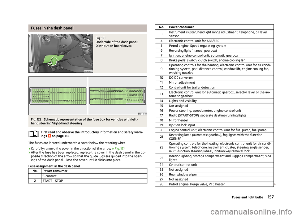
Fuses in the dash panel
Fig. 121
Underside of the dash panel:
Distribution board cover. Fig. 122
Schematic representation of the fuse box for vehicles with left-
hand steering/right-hand steering
First read and observe the introductory information and safety warn-
ings on page 156.
The fuses are located underneath a cover below the steering wheel.
› Carefully remove the cover in the direction of the arrow
» Fig. 121.
› After the fuse has been replaced, replace the cover in the dash panel in the op-
posite direction of the arrow so that the guide lugs are guided into the open-
ings of the dash panel. Close the cover until it clicks into place.
Fuse assignment in the dash panel No. Power consumer
1 S-contact
2 START - STOP ä No. Power consumer
3 Instrument cluster, headlight range adjustment, telephone, oil level
sensor
4 Electronic control unit for ABS/ESC 5 Petrol engine: Speed regulating system
6 Reversing light (manual gearbox) 7 Ignition, engine control unit, automatic gearbox
8 Brake pedal switch, clutch switch, engine cooling fan
9 Operating controls for the heating, electronic control unit for air condi-
tioning system, park distance control, window lift, engine cooling fan,
washing nozzles
10 DC-DC converter 11 Mirror adjustment
12 Control unit for trailer detection
13 Electronic control unit for automatic gearbox, selector lever of the au-
tomatic gearbox
14 Lights and visibility 15 Not assigned
16 Power steering, speedometer, engine control unit 17 Radio (START-STOP), separate daytime running lights
18 Mirror heater 19 Ignition lock input
20 Engine control unit, electronic control unit for fuel pump, fuel pump
21 Reversing lamp (automatic gearbox), fog lights with the function
CORNER
22 Operating controls for the heating, electronic control unit for air condi-
tioning system, telephone, instrument cluster, steering angle sender,
multi-function steering wheel, ignition key removal lock
23 Interior lighting, storage compartment and luggage compartment, side
lights
24 Central control unit 25 Not assigned
26 Rear window wiper 27 Not assigned
28 Petrol engine: Purge valve, PTC heater £ 157
Fuses and light bulbs
Page 160 of 180
No. Power consumer
29 Injection, coolant pump
30 Fuel pump, ignition system, cruise control 31 Lambda probe
32 High pressure fuel pump, pressure valve
33 Engine control unit
34 Engine control unit, vacuum pump
35 Switch illumination, number plate light, parking light, headlamp washer
system
36 Main beam 37 Rear fog light, DC-DC converter
38 Fog lights 39 Air blower for heating
40 Not assigned 41 Heated front seats
42 Rear window heater
43 Horn
44 Windscreen wipers 45 Boot lid lock, central locking system
46 Alarm 47 Cigarette lighter, power socket in the luggage compartment
48 ABS 49 Turn signal lights, brake lights50 DC-DC converter, radio 51 Electric windows (driver's window and rear left window)
52 Electric windows (front passenger's window and rear right)
53 Windscreen washer
54 START-STOP instrument cluster, steering wheel module, multi-function
steering wheel
55 Control unit for automatic gearbox
56 Headlight cleaning system 57 Low beam on the left
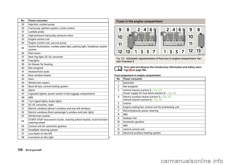
58 Low beam on the right Ð Fuses in the engine compartment
Fig. 123
Schematic representation of fuse box in engine compartment: Ver-
sion
1/version 2
First read and observe the introductory information and safety warn-
ings on page 156.
Fuse assignment in engine compartment
No. Power consumer
1 Generator
2 Not assigned
3 Vehicle interior (variant 1) » Fig. 123 Power supply for fuse block (variant
2) » Fig. 123
4 Electric auxiliary heater (variant 1) » Fig. 123 Vehicle interior (variant
2) » Fig. 123
5 Interior
6 Engine cooling fan, control unit for preheating unit 7 Electrohydraulic power steering
8 ABS 9 Radiator fan
10 Automatic gearbox 11 ABS
12 Central control unit
13 Electrical auxiliary heating system £ ä
158 Do-it-yourself
Page 174 of 180

F
Fire extinguisher 145
First-aid kit 145
Floor mats 74
Front airbag 100
Front seats 44
Fuel 124
Diesel 126
Fuel gauge 9
refer to Fuel 124
Refuelling 124
Unleaded petrol 125
Fuel consumption 110
Fuses Assignment 156
Replacing 156
G
Gear Recommended gear 11
General view Cockpit 7
Glow plug system – indicator light 21
GSM 84
H
Handbrake 72
HBA 72
Head airbag 102
Headlight cleaning system Headlight cleaning system 41
Headlights Driving abroad 113
Headlight cleaning system 41
Head restraint 46Heating 60
Defrosting windows 61
Exterior mirror 42
Rear window 39
Recirculated air mode 61
Seats 46
Heating rear window 39
HHC 72
Horn 7
I
Ignition 70
Ignition lock 70
Immobiliser 69
Information display see MAXI DOT 14
Instrument cluster 8
see Instrument cluster 8
Interior monitor 29
ISOFIX 107
J
Jacking points Raise vehicle 148
Jump-starting 152
L
Lever Main beam 36
Turn signal 36
Light Cockpit 38
Fog lights 35
Fog lights with the function CORNER 37
Hazard warning light system 37
Headlight flasher 36
Main beam 36
Parking light 34Rear fog light 35
Replacing bulbs 159
Turn signal 36
Lights Daytime running lights 35
Headlamp range adjustment 36
Low beam 34
Parking light 37
Parking light on both sides 37
Switching lights on and off 34
Warning lights 16
Loads 164
Lock Central locking system 27
Locking Emergency locking 30
Remote control 28
Locking and unlocking from the inside 27
M
MAXI DOT 14
Main menu 14
Settings 15
Maximum speed 167
MDI 90
Mirror Exterior mirror 42
Make-up 39
Manual dimming interior mirror 42
Mobile phone 84
Connecting to the hands-free system 86
Multifunction display Functions 11
Memory 12
Operation 12
Multimedia 89
172 Index