lock SKODA RAPID 2012 1.G Owner's Guide
[x] Cancel search | Manufacturer: SKODA, Model Year: 2012, Model line: RAPID, Model: SKODA RAPID 2012 1.GPages: 180, PDF Size: 4.36 MB
Page 40 of 180

Interior light
Interior lighting – version 1
Fig. 23
Interior lighting – version 1
Switching on
› Press switch A
» Fig. 23 towards the edge of the light, the symbol
appears.
Switching off
› Press the switch A
» Fig. 23 in the middle position
O.
Operating with the door contact switch
› Press switch A
» Fig. 23 towards the middle of the light, the symbol
ap-
pears.
Reading lights
› Press switch B
» Fig. 23 to switch the reading lights on or off.
If operating lights with the door contact switch is enabled (switch A
» Fig. 23 is
in position ), the light will come on when:
› the vehicle is unlocked;
› one of the doors is opened;
› or the ignition key is removed.
If operating lights with the door contact switch is enabled (switch A
is in position
), the light will turn off when:
› the vehicle is locked;
› the ignition is switched on;
› about 30 seconds after all the doors have been closed.
If a door remains open, or if the switch A
is in the position
, the interior light
goes out after 10
minutes to prevent the battery from discharging. Ð Interior lighting – version 2
Fig. 24
Interior lighting – version 2
Switching on
› Press the switch
» Fig. 24 into position .
Switching off
› Press the switch
» Fig. 24 into position 0.
Operating with the door contact switch
› Press the switch
» Fig. 24 into position .
The same principles apply for interior lighting version 2 as for » page 38, Interior
lighting – version 1 . Ð Interior lights at the rear
Fig. 25
Interior lights at the rear
Press switch » Fig. 25 to turn the light light on or off. Ð
38 Using the system
Page 43 of 180
›
Release the lever. The washer system stops and the wiper continues for anoth-
er 1 to 3 wiper strokes (depending on the duration of the spraying process). The
lever will stay in position after releasing it 6
.
Switching windscreen wipers off
› Move the lever back into the home position 0
» Fig. 28
. ÐHeadlight cleaning system
First read and observe the introductory information and safety warn-
ings on page 39.
When the low beam or main beam are switched on, and the windscreen wiper
lever is pulled into the position 5
» Fig. 28
on page
40, the headlights are
sprayed briefly. To clean the headlights, the windshield is also sprayed after every
ten squirts.
You should remove stubborn dirt (such as insect residues) from the headlight len-
ses at regular intervals, for example when refuelling. The following guidelines
must be observed » page 120, Headlight lenses.
To ensure the proper operation of the cleaning system during the winter, any
snow should be removed from the washer nozzle fixtures and ice should be
cleared with a de-icing spray. CAUTION
Never remove the nozzles from the headlight cleaning system by hand – risk of
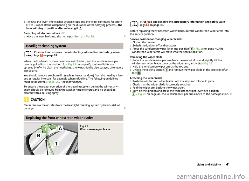
damage! ÐReplacing the front windscreen wiper blades
Fig. 29
Windscreen wiper blade
ä
First read and observe the introductory information and safety warn-
ings on page 39.
Before replacing the windscreen wiper blade, put the windscreen wiper arms into
the service position.
Service position for changing wiper blades
› Closing the bonnet.
› Switch the ignition off and on again.
› Press the windscreen wiper lever into position 4
» Fig. 28
on page
40, the
windscreen wiper arms will move into the service position.
Removing the wiper blade
› Raise the windscreen wiper arm from the rear window and slightly tilt the
windscreen wiper blade towards the wiper arm, arrow A
»
Fig. 29
.
› Hold the windscreen wiper arm at the top end.
› Unlock the locking button 1
and remove the wiper blade in the direction of ar-
row B
.
Attaching the wiper blade
› Push the windscreen wiper blade until the stop and it locks in place.
› Check that the wiper blade is correctly attached.
› Fold the wiper arm back to the windscreen.
› Turn on the ignition and press the windscreen wiper lever into position 4
» Fig. 28 on page 40
, the windscreen wiper arms move to the home position. Ð
ä
41
Lights and visibility
Page 44 of 180
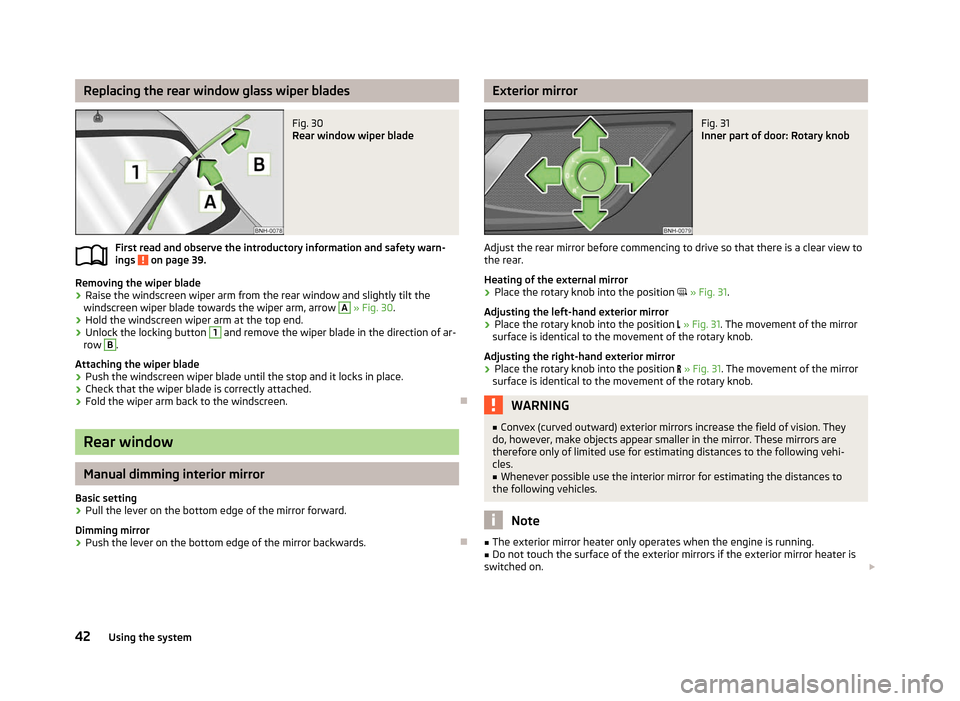
Replacing the rear window glass wiper blades
Fig. 30
Rear window wiper blade
First read and observe the introductory information and safety warn-
ings on page 39.
Removing the wiper blade
› Raise the windscreen wiper arm from the rear window and slightly tilt the
windscreen wiper blade towards the wiper arm, arrow A
» Fig. 30
.
› Hold the windscreen wiper arm at the top end.
› Unlock the locking button 1
and remove the wiper blade in the direction of ar-
row B
.
Attaching the wiper blade
› Push the windscreen wiper blade until the stop and it locks in place.
› Check that the wiper blade is correctly attached.
› Fold the wiper arm back to the windscreen. ÐRear window
Manual dimming interior mirror
Basic setting
› Pull the lever on the bottom edge of the mirror forward.
Dimming mirror
› Push the lever on the bottom edge of the mirror backwards. Ð
ä Exterior mirror
Fig. 31
Inner part of door: Rotary knob
Adjust the rear mirror before commencing to drive so that there is a clear view to
the rear.
Heating of the external mirror
› Place the rotary knob into the position
» Fig. 31.
Adjusting the left-hand exterior mirror
› Place the rotary knob into the position
» Fig. 31. The movement of the mirror
surface is identical to the movement of the rotary knob.
Adjusting the right-hand exterior mirror
› Place the rotary knob into the position
» Fig. 31. The movement of the mirror
surface is identical to the movement of the rotary knob. WARNING
■ Convex (curved outward) exterior mirrors increase the field of vision. They
do, however, make objects appear smaller in the mirror. These mirrors are
therefore only of limited use for estimating distances to the following vehi-
cles.
■ Whenever possible use the interior mirror for estimating the distances to
the following vehicles. Note
■ The exterior mirror heater only operates when the engine is running.
■ Do not touch the surface of the exterior mirrors if the exterior mirror heater is
switched on. £
42 Using the system
Page 47 of 180
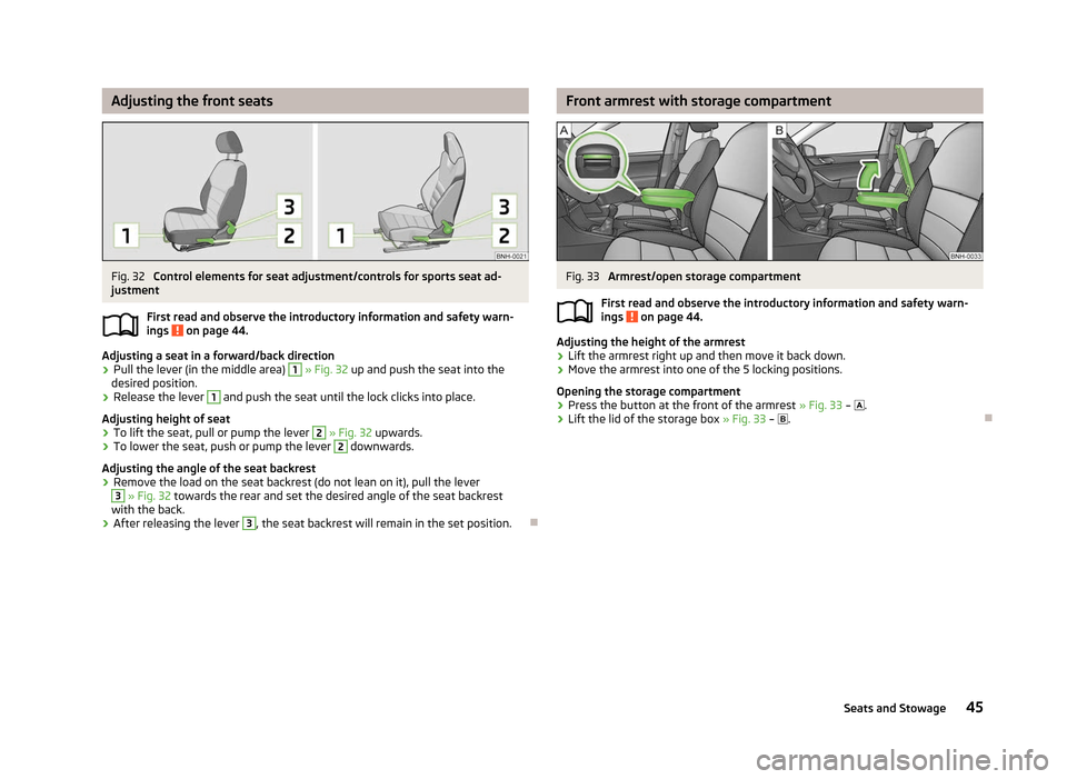
Adjusting the front seats
Fig. 32
Control elements for seat adjustment/controls for sports seat ad-
justment
First read and observe the introductory information and safety warn-
ings on page 44.
Adjusting a seat in a forward/back direction
›
Pull the lever (in the middle area) 1
» Fig. 32
up and push the seat into the
desired position.
› Release the lever 1
and push the seat until the lock clicks into place.
Adjusting height of seat
› To lift the seat, pull or pump the lever 2
» Fig. 32
upwards.
› To lower the seat, push or pump the lever 2
downwards.
Adjusting the angle of the seat backrest
› Remove the load on the seat backrest (do not lean on it), pull the lever 3
» Fig. 32 towards the rear and set the desired angle of the seat backrest
with the back.
› After releasing the lever 3
, the seat backrest will remain in the set position.
Ð
ä Front armrest with storage compartment
Fig. 33
Armrest/open storage compartment
First read and observe the introductory information and safety warn-
ings on page 44.
Adjusting the height of the armrest
›
Lift the armrest right up and then move it back down.
› Move the armrest into one of the 5 locking positions.
Opening the storage compartment
› Press the button at the front of the armrest
» Fig. 33 – .
› Lift the lid of the storage box
» Fig. 33 – . Ð
ä
45
Seats and Stowage
Page 49 of 180
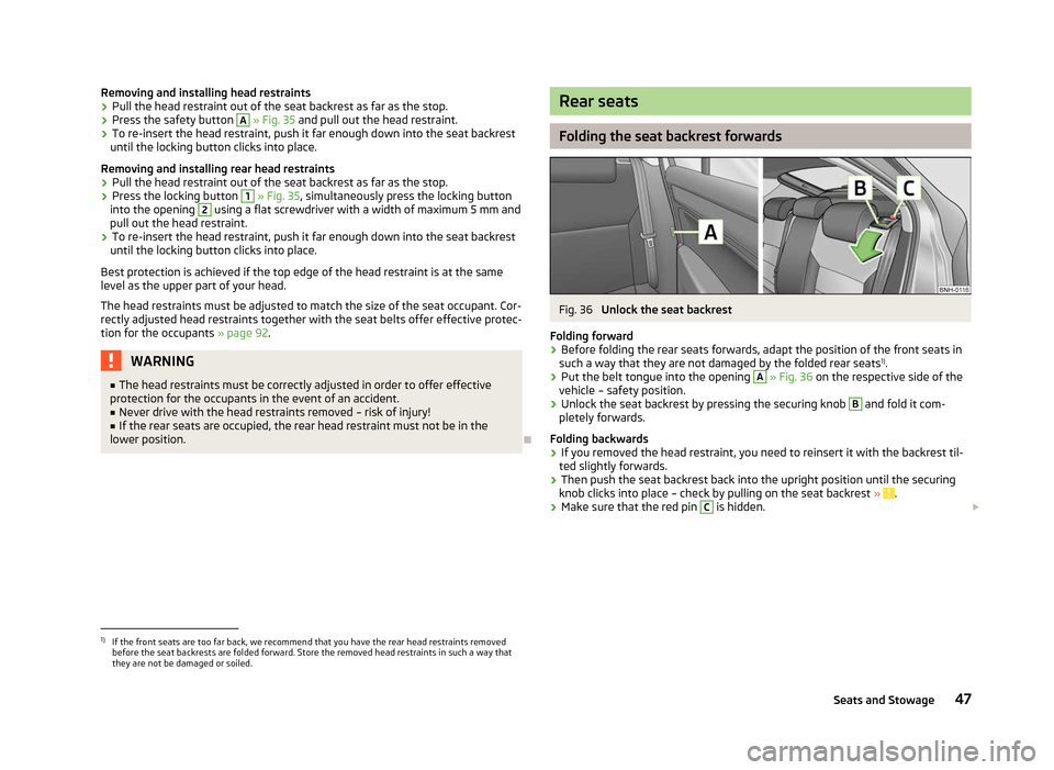
Removing and installing head restraints
›
Pull the head restraint out of the seat backrest as far as the stop.
› Press the safety button A
» Fig. 35 and pull out the head restraint.
› To re-insert the head restraint, push it far enough down into the seat backrest
until the locking button clicks into place.
Removing and installing rear head restraints
› Pull the head restraint out of the seat backrest as far as the stop.
› Press the locking button 1
» Fig. 35, simultaneously press the locking button
into the opening 2
using a flat screwdriver with a width of maximum 5 mm and
pull out the head restraint.
› To re-insert the head restraint, push it far enough down into the seat backrest
until the locking button clicks into place.
Best protection is achieved if the top edge of the head restraint is at the same
level as the upper part of your head.
The head restraints must be adjusted to match the size of the seat occupant. Cor-
rectly adjusted head restraints together with the seat belts offer effective protec-
tion for the occupants » page 92.WARNING
■ The head restraints must be correctly adjusted in order to offer effective
protection for the occupants in the event of an accident.
■ Never drive with the head restraints removed – risk of injury!
■ If the rear seats are occupied, the rear head restraint must not be in the
lower position. Ð Rear seats
Folding the seat backrest forwards
Fig. 36
Unlock the seat backrest
Folding forward
› Before folding the rear seats forwards, adapt the position of the front seats in
such a way that they are not damaged by the folded rear seats 1)
.
› Put the belt tongue into the opening A
» Fig. 36
on the respective side of the
vehicle – safety position.
› Unlock the seat backrest by pressing the securing knob B
and fold it com-
pletely forwards.
Folding backwards
› If you removed the head restraint, you need to reinsert it with the backrest til-
ted slightly forwards.
› Then push the seat backrest back into the upright position until the securing
knob clicks into place – check by pulling on the seat backrest » .
› Make sure that the red pin C
is hidden.
£1)
If the front seats are too far back, we recommend that you have the rear head restraints removed
before the seat backrests are folded forward. Store the removed head restraints in such a way that
they are not be damaged or soiled.
47
Seats and Stowage
Page 50 of 180
WARNING
■ The belts and the belt locks must be in their original position after folding
back the seat backrests – they must be ready to use.
■ The seat backrests must be securely interlocked in position so that no ob-
jects in the boot can slide into the passenger compartment if there is sudden
braking – risk of injury. ■ Ensure that the rear seat backrests are properly engaged. Only then can the
seat belt for the middle seat reliably fulfil its function. CAUTION
Ensure that the seat belts are not damaged when operating the seat backrests.
Under no circumstances must the seat belts be jammed by the folded back seat
backrests. ÐRear armrest
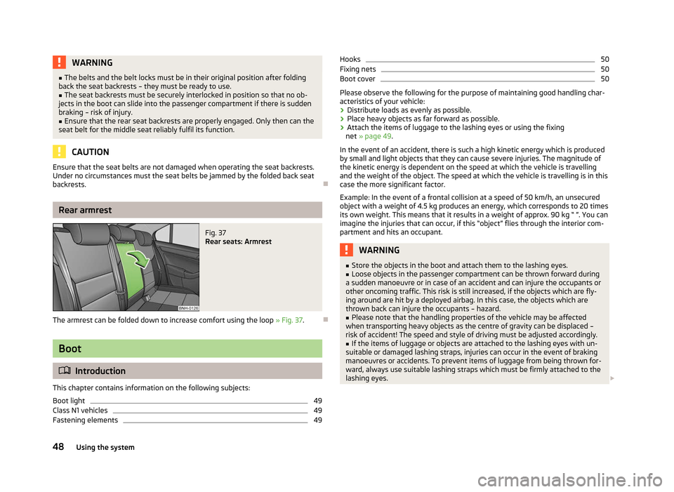
Fig. 37
Rear seats: Armrest
The armrest can be folded down to increase comfort using the loop » Fig. 37.Ð Boot
ä
Introduction
This chapter contains information on the following subjects:
Boot light 49
Class N1 vehicles 49
Fastening elements 49Hooks 50
Fixing nets 50
Boot cover 50
Please observe the following for the purpose of maintaining good handling char-
acteristics of your vehicle:
› Distribute loads as evenly as possible.
› Place heavy objects as far forward as possible.
› Attach the items of luggage to the lashing eyes or using the fixing
net » page 49 .
In the event of an accident, there is such a high kinetic energy which is produced
by small and light objects that they can cause severe injuries. The magnitude of
the kinetic energy is dependent on the speed at which the vehicle is travelling
and the weight of the object. The speed at which the vehicle is travelling is in this
case the more significant factor.
Example: In the event of a frontal collision at a speed of 50 km/h, an unsecured
object with a weight of 4.5 kg produces an energy, which corresponds to 20 times
its own weight. This means that it results in a weight of approx. 90 kg “ ”. You can
imagine the injuries that can occur, if this “object” flies through the interior com-
partment and hits an occupant. WARNING
■ Store the objects in the boot and attach them to the lashing eyes.
■ Loose objects in the passenger compartment can be thrown forward during
a sudden manoeuvre or in case of an accident and can injure the occupants or
other oncoming traffic. This risk is still increased, if the objects which are fly-
ing around are hit by a deployed airbag. In this case, the objects which are
thrown back can injure the occupants – hazard.
■ Please note that the handling properties of the vehicle may be affected
when transporting heavy objects as the centre of gravity can be displaced –
risk of accident! The speed and style of driving must be adjusted accordingly. ■ If the items of luggage or objects are attached to the lashing eyes with un-
suitable or damaged lashing straps, injuries can occur in the event of braking
manoeuvres or accidents. To prevent items of luggage from being thrown for-
ward, always use suitable lashing straps which must be firmly attached to the
lashing eyes. £
48 Using the system
Page 53 of 180
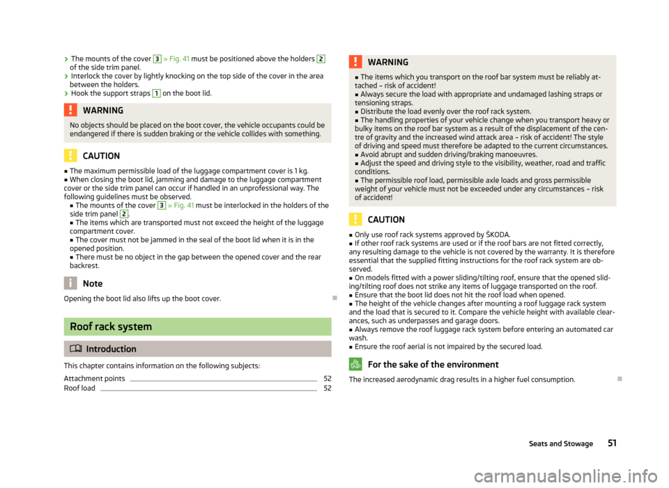
›
The mounts of the cover 3
» Fig. 41 must be positioned above the holders 2
of the side trim panel.
› Interlock the cover by lightly knocking on the top side of the cover in the area
between the holders.
› Hook the support straps 1
on the boot lid.
WARNING
No objects should be placed on the boot cover, the vehicle occupants could be
endangered if there is sudden braking or the vehicle collides with something. CAUTION
■ The maximum permissible load of the luggage compartment cover is 1 kg.
■ When closing the boot lid, jamming and damage to the luggage compartment
cover or the side trim panel can occur if handled in an unprofessional way. The
following guidelines must be observed. ■ The mounts of the cover 3
» Fig. 41 must be interlocked in the holders of the
side trim panel 2
.
■ The items which are transported must not exceed the height of the luggage
compartment cover. ■ The cover must not be jammed in the seal of the boot lid when it is in the
opened position.
■ There must be no object in the gap between the opened cover and the rear
backrest. Note
Opening the boot lid also lifts up the boot cover. ÐRoof rack system
ä
Introduction
This chapter contains information on the following subjects:
Attachment points 52
Roof load 52 WARNING
■ The items which you transport on the roof bar system must be reliably at-
tached – risk of accident!
■ Always secure the load with appropriate and undamaged lashing straps or
tensioning straps.
■ Distribute the load evenly over the roof rack system.
■ The handling properties of your vehicle change when you transport heavy or
bulky items on the roof bar system as a result of the displacement of the cen-
tre of gravity and the increased wind attack area – risk of accident! The style
of driving and speed must therefore be adapted to the current circumstances. ■ Avoid abrupt and sudden driving/braking manoeuvres.
■ Adjust the speed and driving style to the visibility, weather, road and traffic
conditions. ■ The permissible roof load, permissible axle loads and gross permissible
weight of your vehicle must not be exceeded under any circumstances – risk
of accident! CAUTION
■ Only use roof rack systems approved by
ŠKODA.
■ If other roof rack systems are used or if the roof bars are not fitted correctly,
any resulting damage to the vehicle is not covered by the warranty. It is therefore
essential that the supplied fitting instructions for the roof rack system are ob-
served.
■ On models fitted with a power sliding/tilting roof, ensure that the opened slid-
ing/tilting roof does not strike any items of luggage transported on the roof. ■ Ensure that the boot lid does not hit the roof load when opened.
■ The height of the vehicle changes after mounting a roof luggage rack system
and the load that is secured to it. Compare the vehicle height with available clear-
ances, such as underpasses and garage doors.
■ Always remove the roof luggage rack system before entering an automated car
wash. ■ Ensure the roof aerial is not impaired by the secured load. For the sake of the environment
The increased aerodynamic drag results in a higher fuel consumption. Ð
51
Seats and Stowage
Page 61 of 180
Heating and air conditioning system
Heating and air conditioning system
Introductory information
The heating effect is dependent upon the coolant temperature, thus full heat
output only occurs when the engine has reached its operating temperature.
If the cooling system is switched on, the temperature and air humidity drops in
the vehicle. The well-being of the occupants of the car is enhanced as a result of
this particularly at high outside temperatures and a high air humidity. The system
prevents the windows misting up during the cold season of the year.
It is possible to briefly activate recirculated air mode to enhance the cooling ef-
fect.
The air inlet in front of the windscreen must be free of ice, snow or leaves to en-
sure that the heating and cooling system operates properly.
After switching on the cooling Condensation from the evaporator of the air condi-
tioning may drip down and form a puddle below the vehicle. This is quite normal
and not an indication of a leak! WARNING
■ For your own safety and that of other road users, ensure that all the win-
dows are free of ice, snow and misting. Please familiarize yourself about how
to correctly operate the heating and ventilation systems, how to demist and
defrost the windows, as well as with the cooling mode.
■ Do not leave recirculated air mode on over a longer period of time, as “stale”
air can cause fatigue of the driver and passengers, reduce attention levels and
also cause the windows to mist up. The risk of having an accident increases.
Switch off recirculated air mode as soon as the windows start to mist up. Note
■ The used air streams out through the vents in the boot.
■ We recommend that you do not smoke in the vehicle when the recirculating air
mode is operating since the smoke which is drawn at the evaporator from the in-
terior of the vehicle forms deposits in the evaporator of the air conditioning sys- tem. This produces a permanent odour when the air conditioning system is oper-
ating which can only be eliminated through considerable effort and expense (re-
placement of compressor). ■ To ensure that the heating and air conditioning systems work properly, do not
block up the air outlet vents with any objects. Ð Using the air conditioning system economically
The compressor on the air conditioning system uses power from the engine when
in cooling mode which will effect the fuel consumption.
It recommended to open the windows or the doors of a vehicle for which the inte-
rior has been strongly heated through the effect of direct sunlight in order to al-
low the heated air to escape.
The cooling system should not be switched on while travelling when the window
is open.
If the desired interior temperature can also be achieved without activating the
cooling system, fresh air mode should be selected. For the sake of the environment
Pollutant emissions are also reduced when fuel is saved. Ð Operational problems
If the cooling system does not operate at outside temperatures higher than +5 °C,
there is a problem in the system. The reasons for this may be.
› One of the fuses has blown. Check the fuse and replace if necessa-
ry »
page 156 .
› The cooling system has switched off automatically for a short time because the
coolant temperature of the engine is too hot » page 9.
If you cannot rectify the functional fault yourself, or the cooling capacity decrea-
ses, the cooling system must be switched off. Visit a ŠKODA specialist garage. Ð
59
Heating and air conditioning system
Page 70 of 180

Starting-off and Driving
Starting and stopping the engine
ä
Introduction
This chapter contains information on the following subjects:
Adjusting the steering wheel position 69
Power steering 69
Electronic immobiliser 69
Ignition lock 70
Starting engine 70
Switching off the engine 70
WARNING
■ Never adjust the steering wheel when the vehicle is moving only when the
vehicle is stationary!
■ Maintain a distance of 25 cm 1
to the steering wheel
» Fig. 62 on page 69
– . Not maintaining this minimum distance will mean that the airbag system
will not be able to properly protect you – hazard!
■ The lever for adjusting the steering wheel must be locked whilst driving so
that the position of the steering wheel cannot accidently change during the
journey – risk of accident!
■ If the steering wheel is adjusted further towards the head, the protection
provided by the driver airbag in the event of an accident is reduced. Check
that the steering wheel is aligned to the chest. ■ When driving, hold the steering wheel with both hands firmly on the outer
edge in the 9 o'clock and 3
o'clock position. Never hold the steering wheel in
the 12 o'clock position or in any other way (e.g. in the middle or inner edge of
the steering wheel). In such cases, you could severely injure the arms, hands
and head when the driver airbag is deployed.
■ When driving, the ignition key must always be in the position 2
» Fig. 63 on
page 70 (ignition switched on) without the engine running. This position is
indicated by the warning lights coming on. If this is not the case, it could result
in unexpected locking of the steering wheel – risk of accident! WARNING (Continued)
■ Only pull the ignition key from the ignition lock when the vehicle has come
to a complete stop (by applying the handbrake). Otherwise the steering wheel
could block – risk of accident!
■ When leaving the vehicle, the ignition must always be removed. This is par-
ticularly important if children are left in the vehicle. Otherwise the children
could, for example, start the engine – risk of accident or injury!
■ Never leave the engine running in unventilated or closed rooms. The ex-
haust gases of the engine contain besides the odorless and colourless carbon
monoxide a poisonous gas – hazard! Carbon monoxide can cause uncon-
sciousness and death. ■ Never leave the vehicle unattended with the engine running.
■ Never switch off the engine before the vehicle is stationary – risk of acci-
dent! CAUTION
■ You will place great stresses on the power steering system if the steering is
turned to full lock when the vehicle is stationary. Turning the steering to full lock
in such a situation will be accompanied by noises. Never leave the steering wheel
at full lock for more than 15
seconds when the engine is running – risk of damag-
ing the power steering!
■ The starter may only be operated (ignition key position 3
» Fig. 63 on
page 70), if the engine is not running. The starter or engine can be damaged if
the starter is activated when the engine is running. ■ Let go of the ignition key as soon as the engine starts otherwise the starter
could be damaged. ■ Avoid high engine revolutions, full throttle and high engine loads as long as the
engine has not yet reached its operating temperature – risk of damaging the en-
gine!
■ Do not tow start the engine – danger of damaging the engine! On vehicles with
a catalytic converter, unburnt fuel may get into the catalytic converter where it
may ignite. This in turn may damage the catalytic converter. The battery from an-
other vehicle can be used as a jump-start aid » page 152, Jump-starting.
■ Do not switch the engine off immediately at the end of your journey after the
engine has been operated over a prolonged period at high loads but leave it to
run at an idling speed for about 1
minute. This prevents any possible accumulation
of heat when the engine is switched off. £
68 Using the system
Page 71 of 180

For the sake of the environment
Do not warm up the engine while the vehicle is stationary. If possible, start your
journey as soon as the engine has started. Through this the engine reaches its
operating temperature more rapidly and the pollutant emissions are lower. Note
■ The engine can only be started with a genuine ŠKODA key with the matching
code. ■ The engine running noises may louder at first be louder for a short time after
starting the cold engine. This is quite normal and is not an operating problem. ■ After switching off the ignition, the radiator fan can intermittently continue to
operate for approx. 10
minutes.
■ If the engine does not start up after a second attempt, the fuse for the fuel
pump may have a fault. Check the fuse and replace, if necessary » page 157,
Fuses in the dash panel
or seek assistance from a ŠKODA specialist garage.
■ We recommend locking the steering wheel
whenever leaving the vehicle. This
acts as a deterrent against the attempted theft of your car. ÐAdjusting the steering wheel position
Fig. 62
Adjustable steering wheel: Lever below the steering column/safe
distance to the steering wheel
First read and observe the introductory information and safety warn-
ings on page 68.
The height and forward/back position of the steering wheel can be adjusted.
›
First of all adjust the driver's seat
» page 44, Front seats.
› Pull the lever below the steering wheel down
» Fig. 62 – .
ä ›
Adjust the steering wheel to the desired position (with regard to the height and
forward/back position).
› Push the lever upwards to the stop. Ð Power steering
First read and observe the introductory information and safety warn-
ings on page 68.
The power steering enables you to steer the vehicle with less physical force.
It is still possible to fully steer the vehicle if the power steering fails or if the en-
gine is not running (vehicle being towed in). However, greater physical effort is
required to turn the steering wheel. Ð Electronic immobiliser
First read and observe the introductory information and safety warn-
ings on page 68.
An electronic chip is integrated in the head of the key. The immobiliser is deacti-
vated with the aid of this chip when the key is inserted in the ignition lock. The
electronic immobiliser is automatically activated when the ignition key is with-
drawn from the lock.
The engine will not start if a non-authorized ignition key is used.
The following is displayed in the information display: Immobilizer active. Ð
ä
ä
69
Starting-off and Driving