low beam SKODA RAPID 2012 1.G Owner's Manual
[x] Cancel search | Manufacturer: SKODA, Model Year: 2012, Model line: RAPID, Model: SKODA RAPID 2012 1.GPages: 180, PDF Size: 4.36 MB
Page 19 of 180
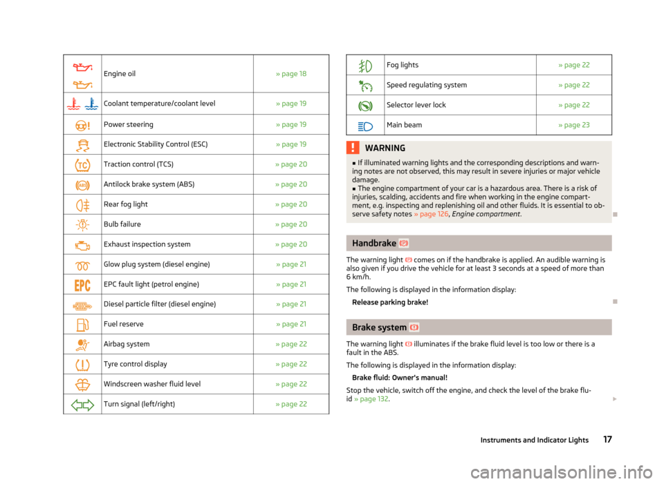
Engine oil
» page 18
Coolant temperature/coolant level
» page 19
Power steering
» page 19
Electronic Stability Control (ESC)
» page 19
Traction control (TCS)
» page 20
Antilock brake system (ABS)
» page 20
Rear fog light
» page 20
Bulb failure
» page 20
Exhaust inspection system
» page 20
Glow plug system (diesel engine)
» page 21
EPC fault light (petrol engine)
» page 21
Diesel particle filter (diesel engine)
» page 21
Fuel reserve
» page 21
Airbag system
» page 22
Tyre control display
» page 22
Windscreen washer fluid level
» page 22
Turn signal (left/right)
» page 22
Fog lights
» page 22
Speed regulating system
» page 22
Selector lever lock
» page 22
Main beam
» page 23 WARNING
■ If illuminated warning lights and the corresponding descriptions and warn-
ing notes are not observed, this may result in severe injuries or major vehicle
damage.
■ The engine compartment of your car is a hazardous area. There is a risk of
injuries, scalding, accidents and fire when working in the engine compart-
ment, e.g. inspecting and replenishing oil and other fluids. It is essential to ob-
serve safety notes »
page 126, Engine compartment . Ð Handbrake
The warning light comes on if the handbrake is applied. An audible warning is
also given if you drive the vehicle for at least 3
seconds at a speed of more than
6 km/h.
The following is displayed in the information display:
Release parking brake! Ð Brake system
The warning light illuminates if the brake fluid level is too low or there is a
fault in the ABS.
The following is displayed in the information display:
Brake fluid: Owner's manual!
Stop the vehicle, switch off the engine, and check the level of the brake flu-
id » page 132. £
17
Instruments and Indicator Lights
Page 22 of 180

Note
If the vehicle's battery has been disconnected and reconnected, the warning light comes on after switching on the ignition. The warning light should go out after
driving a short distance. ÐTraction control system (TCS)
The warning light flashes to show that the ASR is currently operating.
If the warning light comes on immediately after starting the engine, the ASR
can be switched off for technical reasons. Switch the ignition off and on again. If
the warning light does not light up after you switch the engine back on, the ASR
is fully functional again.
If the warning light lights up, there is a fault in the ASR.
The following is displayed in the information display: Error: traction control (ASR)
Seek help from a
ŠKODA specialist garage.
Further information » page 73, Traction control (ASR) . ÐAntilock brake system (ABS)
If the warning light lights up, there is a fault in the ABS.
The following is displayed in the information display: Error: ABS
The vehicle will only be braked by the normal brake system without the ABS.
Seek help from a
ŠKODA specialist garage. WARNING
■ If you have to stop for technical reasons, then park the vehicle at a safe dis-
tance from the traffic, switch off the engine and activate the hazard warning
light system » page 37.
■ If the warning light » page 17
is lit simultaneously with warning light ,
do not continue your journey! Seek help from a ŠKODA specialist garage.
■ A fault to the ABS system or the braking system can increase the vehicle's
braking distance – risk of accident! Ð The rear fog light
The warning light comes on when the rear fog lights are operating » page 35.Ð Bulb failure
The warning light comes on if a bulb is faulty:
› within a few seconds of the ignition being switched on;
› when switching on the defective light bulb.
The following is displayed in the information display: Check front-right dipped beam! Note
The rear side lights and the licence plate lighting have several light bulbs. The in-
dicator light only lights up if all light bulbs of the licence plate lighting or the
parking light (in one rear light) are defective. For this reason, regular check that
these light bulbs are working correctly. Ð Exhaust inspection system
If the warning light lights up, there is a fault in the exhaust inspection system.
The engine control unit allows the vehicle to run in emergency mode.
Seek help from a
ŠKODA specialist garage. Ð
20 Using the system
Page 24 of 180
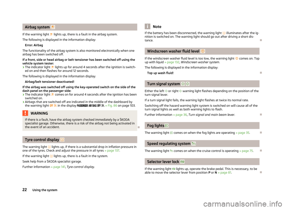
Airbag system
If the warning light lights up, there is a fault in the airbag system.
The following is displayed in the information display: Error: Airbag
The functionality of the airbag system is also monitored electronically when one
airbag has been switched off.
If a front, side or head airbag or belt tensioner has been switched off using the
vehicle system tester:
› The indicator light
lights up for around
4 seconds after the ignition is switch-
ed on and then flashes for around 12 seconds.
The following is displayed in the information display: Airbag/belt tensioner deactivated!
If the airbag was switched off using the key-operated switch on the side of the
dash panel on the passenger side:
› The indicator light
comes on for around 4 seconds after the ignition has been
switched on.
› Airbags that are switched off are indicated in the middle of the dashboard by
the warning light
in the display » Fig. 86 on page 103. WARNING
If there is a fault, have the airbag system checked immediately by a ŠKODA
specialist garage. Otherwise, there is a risk of the airbag not being activated in
the event of an accident. ÐTyre control display
The warning light lights up, if there is a substantial drop in inflation pressure in
one of the tyres. Check and adjust the pressure in all tyres » page 137.
If the warning light lights up, there is a fault in the system.
Seek help from a ŠKODA specialist garage.
Further information »
page 141, Tyre control display . Note
If the battery has been disconnected, the warning light illuminates after the ig-
nition is switched on. The warning light should go out after driving a short dis-
tance. Ð Windscreen washer fluid level
If the windscreen washer fluid level is too low, the warning light comes on. Top
up with liquid » page 132, Windscreen washer system.
The following is displayed in the information display: Top up wash fluid! Ð Turn signal system
Either the left or right warning light flashes depending on the position of the
turn signal lever.
If a turn signal light fails, the warning light flashes at twice its normal rate.
Switching off the hazard warning light system is switched on will cause all of the
turn signal lights as well as both warning lights to flash.
Further information » page 36, Turn signal and main beam lever .Ð Fog lights
The warning light comes on when the fog lights are operating » page 35.Ð Speed regulating system
The warning light comes on when the cruise control is operating » page 75.Ð Selector lever lock
If the warning light lights up, operate the brake pedal. This is necessary, to be
able to move the selector lever from position P or N » page 81. Ð
22 Using the system
Page 36 of 180
Lights and visibility
Lights
ä
Introduction
This chapter contains information on the following subjects:
Switching lights on and off 34
Function DAY LIGHT (daytime running lights) 35
Fog lights 35
Rear fog light 35
Headlamp range adjustment 36
Turn signal and main beam lever 36
Parking light 37
Fog lights with the function CORNER 37
Switches for the hazard warning light system 37
On models fitted with right-hand steering the position of certain switches differs
from that shown in » Fig. 18 on page 34. The symbols which mark the switch po-
sitions are identical, however. WARNING
Never drive with only the side lights on! The side lights are not bright enough
to light up the road sufficiently in front of you or to be seen by other oncom-
ing traffic. Therefore always switch on the low beam when it is dark or if visi-
bility is poor. CAUTION
■ The activation of the lights should only be undertaken in accordance with na-
tional legal requirements.
■ The driver is always responsible for the correct settings and use of the lights. Note
■ If the light switch is in the position , the ignition key is removed and the driv-
er's door is open, an audible warning signal will sound. The audible warning signal
is switched off by means of the door contact when the driver's door is closed (ig-
nition off), however, the side lights remain on to illuminate the parked vehicle if
necessary. ■ In the event of cool or humid weather conditions, the headlights can be misted
up from inside. The temperature difference between interior and external area of
the headlight lenses is decisive. When the driving lights are switched on, the light
outlet surfaces are free from mist after a short period, although the headlight
lenses may still be misted up in the peripheral areas. It also concerns reverse light
and turn signal lights. This mist has no influence on the life of the lighting system. Ð Switching lights on and off
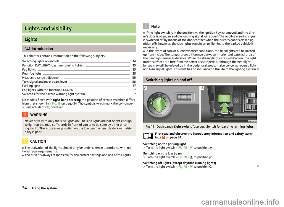
Fig. 18
Dash panel: Light switch/fuse box: Switch for daytime running lights
First read and observe the introductory information and safety warn-
ings on page 34.
Switching on the parking light
›
Turn the light switch
» Fig. 18 – to position .
Switching on the low beam
› Turn the light switch
» Fig. 18 – to position .
Switching off lights (except daytime running lights)
› Turn the light switch
» Fig. 18 – to position 0.Ð
ä
34 Using the system
Page 38 of 180

Headlamp range adjustment
Fig. 20
Dash panel: Lights and visibility
First read and observe the introductory information and safety warn-
ings on page 34.
›
Turn the control dial
» Fig. 20 to the desired width of illumination.
Settings
The positions correspond approximately to the following car load. Front seats occupied, boot empty.
All seats occupied, boot empty.
All seats occupied, boot loaded.
Driver seat occupied, boot loaded. CAUTION
Always adjust the headlight range adjustment in such a way that:
■ it does not dazzle other road users, especially oncoming traffic;
■ and the range is sufficient for safe driving. Note
We recommend you adjust the headlight beam when the low beam is switched
on. Ð
ä -
1
2
3 Turn signal and main beam lever
Fig. 21
Turn signal and main beam lever
First read and observe the introductory information and safety warn-
ings on page 34.
The parking light and headlight flasher are also operated with the turn signal and
main beam lever.
Right and left turn signal light
› Push the lever
» Fig. 21 upwards A
or downwards B
.
› If you only wish to flash three times (the "convenience turn signal"), briefly
push the lever to the upper or lower pressure point and release again.
› Turn signal for changing lanes – to only flash briefly, move the lever up or down
to the pressure point and hold it in this position.
Main beam
› Switch on the low beam » page 34
.
› Press the lever
» Fig. 21 in the direction of arrow C
.
› The main beam is switched off by pulling the lever into the initial position in the
direction of arrow D
.
Headlight flasher
› Pull the lever
» Fig. 21 towards the steering wheel (spring-tensioned position)
in the direction of the arrow D
.
Parking light
Description of the operation » page 37 CAUTION
Only use the main beam or the headlight flasher if other road users will not be
dazzled. £
ä
36 Using the system
Page 39 of 180

Note
■ The turn signal system only operates when the ignition is switched on. The cor-
responding warning light or in the instrument cluster also flashes.
■ The turn signal is automatically cancelled after negotiating a curve.
■ The warning light flashes at twice its normal rate if a bulb for the turn signal
light fails. ÐParking light
First read and observe the introductory information and safety warn-
ings on page 34.
Parking light
› Switch off the ignition.
› Pull the turn signal light lever
» Fig. 21 on page 36 upwards or downwards – the
side light on the right or left side of the vehicle is switched.
Parking light on both sides
› Turn the light switch
» Fig. 18 on page 34 – into the position and lock the
vehicle. Note
■ The parking light can only be activated if the ignition is switched off.
■ If the right or left turn signal light has been switched on and the ignition is
switched off, the parking light is not automatically switched on. ÐFog lights with the function CORNER
First read and observe the introductory information and safety warn-
ings on page 34.
The fog lights with the function CORNER are designed to improve the illumination
of the surrounding area near the vehicle when turning, parking, etc. ä
ä The fog lights with the function CORNER are adjusted according to the steering
angle or after switching on the turn signal light
1)
in the following circumstances:
› the vehicle is stationary and the engine is running or it moves with a speed of
maximum 40 km/h;
› the daytime running lights are not switched on;
› the low beam is switched on;
› the fog lights are not switched on;
› no reverse gear is engaged. Ð Switches for the hazard warning light system
Fig. 22
Dash panel: Switch for hazard
warning lights
First read and observe the introductory information and safety warn-
ings on page 34.
›
Press switch
» Fig. 22 to switch the hazard warning light system on or off.
All the turn signal lights on the vehicle flash at the same time when the hazard
warning light system is switched on. The warning light for the turn signals and
the warning light in the switch also flash at the same time. The hazard warning
light system can also be operated if the ignition is switched off.
The hazard warning light system is switched on automatically if an airbag is de-
ployed in the event of an accident. Note
The hazard warning light system must be switched on if, for example:
■ you encounter a traffic congestion;
■ your vehicle breaks down or an emergency situation occurs. Ð
ä
1)
If both switch on versions are conflicting, for example if the steering wheel is turned to the left and
the right turn signal light is switched on, the turn signal light has the higher priority.
37
Lights and visibility
Page 43 of 180
›
Release the lever. The washer system stops and the wiper continues for anoth-
er 1 to 3 wiper strokes (depending on the duration of the spraying process). The
lever will stay in position after releasing it 6
.
Switching windscreen wipers off
› Move the lever back into the home position 0
» Fig. 28
. ÐHeadlight cleaning system
First read and observe the introductory information and safety warn-
ings on page 39.
When the low beam or main beam are switched on, and the windscreen wiper
lever is pulled into the position 5
» Fig. 28
on page
40, the headlights are
sprayed briefly. To clean the headlights, the windshield is also sprayed after every
ten squirts.
You should remove stubborn dirt (such as insect residues) from the headlight len-
ses at regular intervals, for example when refuelling. The following guidelines
must be observed » page 120, Headlight lenses.
To ensure the proper operation of the cleaning system during the winter, any
snow should be removed from the washer nozzle fixtures and ice should be
cleared with a de-icing spray. CAUTION
Never remove the nozzles from the headlight cleaning system by hand – risk of
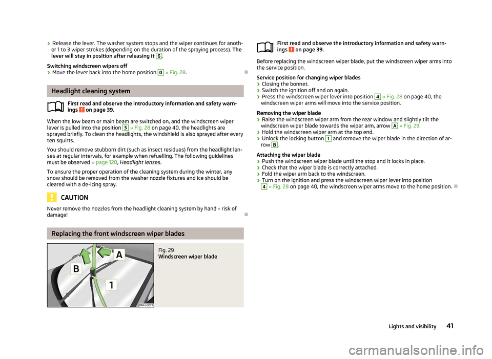
damage! ÐReplacing the front windscreen wiper blades
Fig. 29
Windscreen wiper blade
ä
First read and observe the introductory information and safety warn-
ings on page 39.
Before replacing the windscreen wiper blade, put the windscreen wiper arms into
the service position.
Service position for changing wiper blades
› Closing the bonnet.
› Switch the ignition off and on again.
› Press the windscreen wiper lever into position 4
» Fig. 28
on page
40, the
windscreen wiper arms will move into the service position.
Removing the wiper blade
› Raise the windscreen wiper arm from the rear window and slightly tilt the
windscreen wiper blade towards the wiper arm, arrow A
»
Fig. 29
.
› Hold the windscreen wiper arm at the top end.
› Unlock the locking button 1
and remove the wiper blade in the direction of ar-
row B
.
Attaching the wiper blade
› Push the windscreen wiper blade until the stop and it locks in place.
› Check that the wiper blade is correctly attached.
› Fold the wiper arm back to the windscreen.
› Turn on the ignition and press the windscreen wiper lever into position 4
» Fig. 28 on page 40
, the windscreen wiper arms move to the home position. Ð
ä
41
Lights and visibility
Page 115 of 180

›
The use of solvent-free adhesives.
› No CFCs used in the production process.
› Without use of mercury.
› Use of water-soluble paints.
Trade-in and recycling of old cars
ŠKODA
meets the requirements of the brand and its products with regard to pro-
tecting the environment and the preserving resources. All new ŠKODA vehicles
can be utilized up to 95 % and always 1)
be returned. In a lot of countries sufficient
trade-in networks have been created, where you can trade-in your vehicle. After
you trade-in your vehicle, you will receive a confirmation stating the recycling in
accordance with environmental regulations. Note
Detailed information about the trade-in and recycling of old cars is available from
a ŠKODA Service Partner. ÐDriving abroad
Introductory information
In certain countries it is also possible that the
ŠKODA Service Partner network is
limited or has not been established yet. This is the reason why procuring certain
spare parts may be somewhat complicated and specialist garages may only be
able to make limited repairs. ŠKODA in the Czech Republic and its importers are
happy to provide information about technical aspects of the vehicle, required
maintenance work and possibilities for getting repairs done. ÐUnleaded petrol
A vehicle fitted with a petrol engine must always be refuelled with unleaded pet-
rol » page 125, Unleaded petrol . Information regarding the locations of filling sta-
tions that offer unleaded petrol is, for example, provided by the automobile asso-
ciations. Ð Headlights
The low beam of your headlights is set asymmetrically. It illuminates the side of
the road on which the vehicle is being driven to a greater extent.
When driving in countries in which the traffic drives on the other side of the road
than in your home country, the asymmetrical low beam may dazzle oncoming
drivers. To prevent oncoming traffic from being dazzled, the headlights must be
adjusted by a
ŠKODA Service Partner. Note
Further information on adjusting the headlights is available from a ŠKODA Service
Partner. Ð Avoiding damage to your vehicle
To prevent damage to your vehicle, pay special attention: › When driving on poorly maintained roads and lanes
› When driving over kerb stones
› When driving up steep ramps
› So that any low-slung parts, such as the spoiler and exhaust, do not touch the
ground and get damaged
This particularly applies to models with a sport suspension and also when your
vehicle is fully laden. Ð1)
Subject to fulfilment of the national legal requirements.
113
Driving and the Environment
Page 117 of 180

Towing a trailer
Towing a trailer
Technical requirements
If your vehicle has already been factory-fitted with a towing device or is fitted
with a towing device from ŠKODA Original Accessories, then it meets all of the
technical requirements and national legal provisions for towing a trailer.
On vehicles with a towing device, the ball rod is detachable and is stowed togeth-
er with separate operating instructions in the spare wheel well or in the compart-
ment for the spare wheel within the boot » page 145, Vehicle tool kit .
Your vehicle is fitted with a 13-pin power socket for the electrical connection be-
tween the vehicle and trailer. If the trailer that is to be towed has a 7-pin connec-
tor, you can use a suitable adapter from
ŠKODA Original Accessories.
If a towing device is retrofitted, it must be completed in accordance with the
manufacturer's specifications. Note
If you have any questions, please contact a ŠKODA Service Partner. ÐLoading a trailer
Loading a trailer
The vehicle/trailer combination must be balanced, whereby the maximum permis-
sible drawbar load must be utilised. If the drawbar load is too low, it jeopardises
the performance of the vehicle/trailer combination.
Distribution of the load
Distribute the load in the trailer in such a way that heavy items are located as
close to the axle as possible. Secure the items from slipping.
The distribution of the weight is very poor if your vehicle is unladen and the trail-
er is laden. Maintain a particularly low speed if you cannot avoid driving with this
combination. Tyre pressure
Correct the tyre inflation pressure on your vehicle for a
“full load” » page 138 ,
Service life of tyres.
Trailer load
The permissible trailer load must not be exceeded under any circumstan-
ces » page 164 , Technical data .
The trailer loads specified apply only to altitudes up to 1 000 metres above mean
sea level. As the engine output drops at an increasing altitude due to the declin-
ing air pressure and therefore the climbing ability is also reduced, this means that
the maximum permissible towed weight must be reduced by 10 % for every fur-
ther increase of 1 000 m in height. The towed weight comprises the actual weight
of the (loaded) towing vehicle and the (loaded) trailer. Always drive particularly
carefully with the trailer.
The trailer and drawbar load information on the type plate of the towing device
are merely test data for the towing device The vehicle-specific values are detailed
in the vehicle documents. WARNING
■ If the maximum permissible axle and drawbar load and the maximum per-
missible total or towed weight of the vehicle and the trailer are exceeded this
can cause accidents and serious injuries.
■ Slipping loads can significantly affect the stability and safety of the vehicle/
trailer combination, causing accidents and serious injuries. Ð Towing a trailer
Exterior mirrors
You have to have additional exterior mirrors fitted if you are not able to see the
traffic behind the trailer with the standard rear-view mirrors. The national legal
requirements must be observed.
Headlights
The headlight settings must be checked before starting a journey with a coupled
trailer. If necessary, adjust the settings with the headlight beam adjust-
ment » page 36 , Headlamp range adjustment .
Driving speed
For safety reasons, do not drive faster than the maximum permissible speed indi-
cated on the trailer. £
115
Towing a trailer
Page 160 of 180
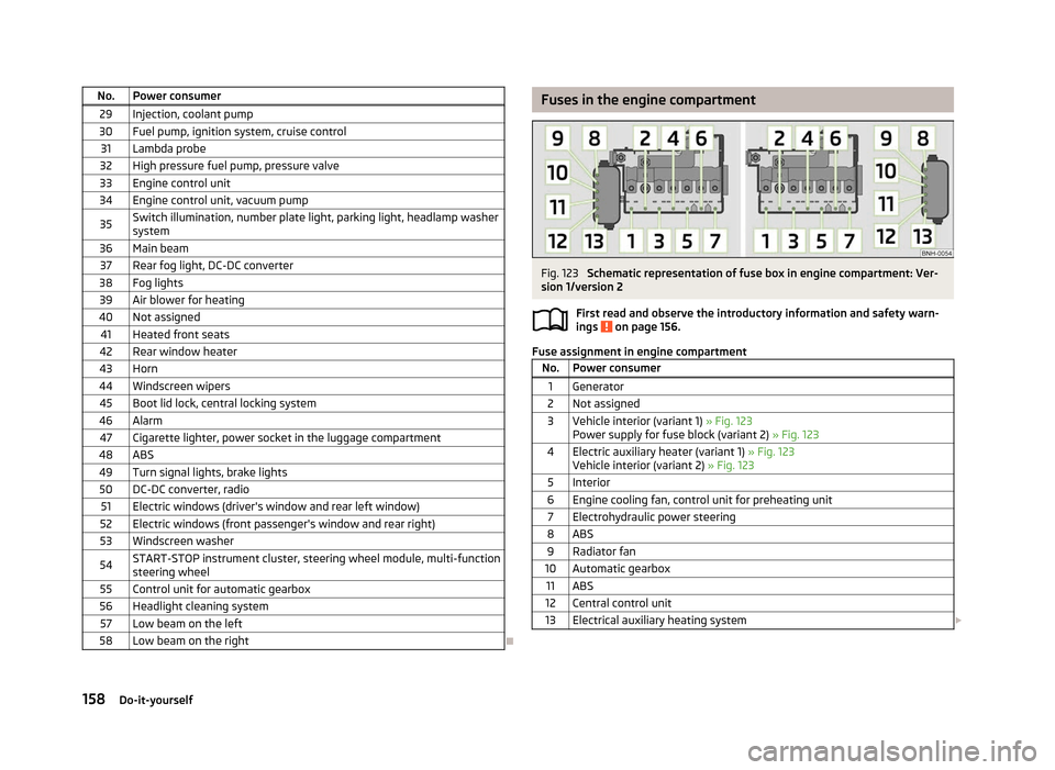
No. Power consumer
29 Injection, coolant pump
30 Fuel pump, ignition system, cruise control 31 Lambda probe
32 High pressure fuel pump, pressure valve
33 Engine control unit
34 Engine control unit, vacuum pump
35 Switch illumination, number plate light, parking light, headlamp washer
system
36 Main beam 37 Rear fog light, DC-DC converter
38 Fog lights 39 Air blower for heating
40 Not assigned 41 Heated front seats
42 Rear window heater
43 Horn
44 Windscreen wipers 45 Boot lid lock, central locking system
46 Alarm 47 Cigarette lighter, power socket in the luggage compartment
48 ABS 49 Turn signal lights, brake lights50 DC-DC converter, radio 51 Electric windows (driver's window and rear left window)
52 Electric windows (front passenger's window and rear right)
53 Windscreen washer
54 START-STOP instrument cluster, steering wheel module, multi-function
steering wheel
55 Control unit for automatic gearbox
56 Headlight cleaning system 57 Low beam on the left
58 Low beam on the right Ð Fuses in the engine compartment
Fig. 123
Schematic representation of fuse box in engine compartment: Ver-
sion
1/version 2
First read and observe the introductory information and safety warn-
ings on page 156.
Fuse assignment in engine compartment
No. Power consumer
1 Generator
2 Not assigned
3 Vehicle interior (variant 1) » Fig. 123 Power supply for fuse block (variant
2) » Fig. 123
4 Electric auxiliary heater (variant 1) » Fig. 123 Vehicle interior (variant
2) » Fig. 123
5 Interior
6 Engine cooling fan, control unit for preheating unit 7 Electrohydraulic power steering
8 ABS 9 Radiator fan
10 Automatic gearbox 11 ABS
12 Central control unit
13 Electrical auxiliary heating system £ ä
158 Do-it-yourself