boot SKODA RAPID 2013 1.G Owner's Guide
[x] Cancel search | Manufacturer: SKODA, Model Year: 2013, Model line: RAPID, Model: SKODA RAPID 2013 1.GPages: 226, PDF Size: 15.16 MB
Page 122 of 226
Towing a trailer
Towing device
Introduction
This chapter contains information on the following subjects:
Description
119
Adjusting the ready position
120
Fitting the ball head
121
Check proper fitting
121
Removing the ball head
122
Use and care
122
If your vehicle has already been factory-fitted with a towing device or is fitted
with a towing device from ŠKODA Original Accessories, then it meets all of the
technical requirements and national legal regulations for towing a trailer.
Your vehicle is fitted with a 13-pin power socket for the electrical connection be-
tween the vehicle and trailer. If the trailer that is to be towed has a 7-pin connec-
tor , you can use a suitable adapter from ŠKODA Original Accessories.
The maximum trailer drawbar load is 50 kg.
WARNING■
Check that the tow bar is seated correctly and is secured in the mounting
recess before the start of every journey.■
Do not use the tow bar if it is not correctly inserted and secured in the
mounting recess.
■
Do not use the towing device if it is damaged or if there are parts missing.
■
Do not modify or adapt the towing device in any way.
■
Never release the tow bar while the trailer is still coupled.
CAUTION
Take care when handling the tow bar so as to avoid damaging the paintwork on
the bumper.
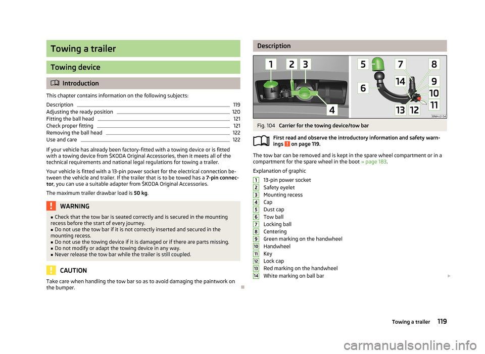
DescriptionFig. 104
Carrier for the towing device/tow bar
First read and observe the introductory information and safety warn-
ings
on page 119.
The tow bar can be removed and is kept in the spare wheel compartment or in a
compartment for the spare wheel in the boot » page 183.
Explanation of graphic 13-pin power socket
Safety eyelet
Mounting recess
Cap
Dust cap
Tow ball
Locking ball
Centering
Green marking on the handwheel
Handwheel
Key
Lock cap
Red marking on the handwheel
White marking on ball bar
1234567891011121314119Towing a trailer
Page 125 of 226
The handwheel is locked and the key is removed.
The cap B
is on the handwheel.
The tow bar does not come out of the mounting recess even after heavy
“shaking”.WARNINGDo not use the towing device unless the tow bar has been properly locked!
Removing the ball head
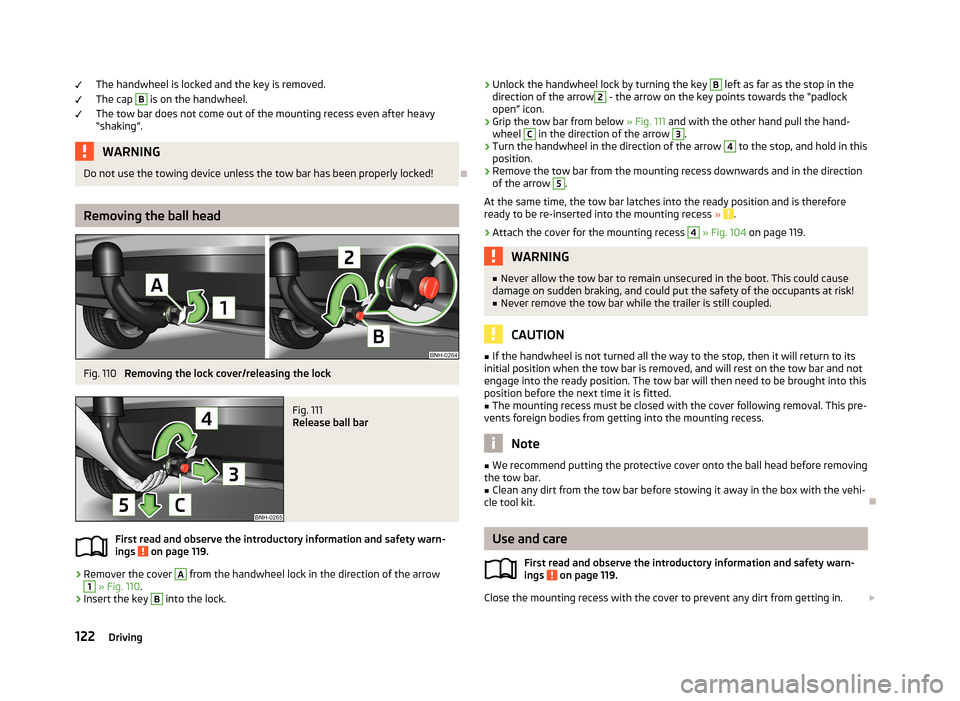
Fig. 110
Removing the lock cover/releasing the lock
Fig. 111
Release ball bar
First read and observe the introductory information and safety warn-
ings on page 119.
›
Remover the cover
A
from the handwheel lock in the direction of the arrow
1
» Fig. 110 .
›
Insert the key
B
into the lock.
›
Unlock the handwheel lock by turning the key B left as far as the stop in the
direction of the arrow2 - the arrow on the key points towards the “padlock
open” icon.›
Grip the tow bar from below » Fig. 111 and with the other hand pull the hand-
wheel
C
in the direction of the arrow
3
.
›
Turn the handwheel in the direction of the arrow
4
to the stop, and hold in this
position.
›
Remove the tow bar from the mounting recess downwards and in the direction
of the arrow
5
.
At the same time, the tow bar latches into the ready position and is therefore
ready to be re-inserted into the mounting recess »
.
›
Attach the cover for the mounting recess
4
» Fig. 104 on page 119.
WARNING■
Never allow the tow bar to remain unsecured in the boot. This could cause
damage on sudden braking, and could put the safety of the occupants at risk!■
Never remove the tow bar while the trailer is still coupled.
CAUTION
■ If the handwheel is not turned all the way to the stop, then it will return to its
initial position when the tow bar is removed, and will rest on the tow bar and not
engage into the ready position. The tow bar will then need to be brought into this position before the next time it is fitted.■
The mounting recess must be closed with the cover following removal. This pre-
vents foreign bodies from getting into the mounting recess.
Note
■ We recommend putting the protective cover onto the ball head before removing
the tow bar.■
Clean any dirt from the tow bar before stowing it away in the box with the vehi-
cle tool kit.
Use and care
First read and observe the introductory information and safety warn-
ings
on page 119.
Close the mounting recess with the cover to prevent any dirt from getting in.
122Driving
Page 126 of 226
Always check the tow bar before hitching a trailer. Apply suitable grease where
necessary.
Use the protective cover when stowing away the tow bar, in order to stop the
boot from getting dirty.
In the event of dirt, clean the surfaces of the mounting recess and treat with a
suitable preservative.
CAUTION
Apply grease to the upper part of the mounting recess. Make sure you do not re-
move any grease.
Trailer
Introduction
This chapter contains information on the following subjects:
Loading a trailer
123
Driving with a trailer
124
Anti-theft alarm system
125WARNINGAlways drive particularly carefully with the trailer.
Loading a trailer
First read and observe the introductory information and safety warn-
ings
on page 123.
The vehicle/trailer combination must be balanced, whereby the maximum permis-
sible drawbar load must be utilised. If the drawbar load is too low, it jeopardises the performance of the vehicle/trailer combination.
Distribution of the load
Distribute the load in the trailer in such a way that heavy items are located as close to the axle as possible. Secure the items from slipping.
The distribution of the weight is very poor if your vehicle is unladen and the trail-
er is laden. Maintain a particularly low speed if you cannot avoid driving with this
combination.
Tyre pressure
Correct the tyre inflation pressure on your vehicle for a “full load” » page 176,
Service life of tyres .
Trailer load
The permissible trailer load must not be exceeded under any circumstan- ces » page 207 , Technical data .
The trailer loads specified apply only to altitudes up to 1 000 metres above mean
sea level.
The engine output falls as altitude increases, as does the vehicle's climbing pow-
er. Therefore, for every additional 1000 m in height (or part), the maximum per-
missible towed weight must be reduced by 10%.
The towed weight is made up of the actual weights of the loaded towing vehicle
and the loaded trailer.
The trailer and drawbar load information on the type plate of the towing device is
merely a test value for the towing device. The vehicle-specific values are detailed
in the vehicle documents.WARNING■ Do not exceed the maximum permissible axle and drawbar load and the
maximum permissible total or towed weight of the vehicle and the trailer –
risk of accident and serious injury!■
Slipping loads can significantly impair the stability and safety of the vehicle/
trailer combination – risk of accident and serious injury!
123Towing a trailer
Page 150 of 226
General Maintenance
Vehicle care
Service intervals
Introduction
This chapter contains information on the following subjects:
Overview of service intervals
147
Fixed service intervals QI1 - QI4
148
Variable service interval QI6
148
Information about the ŠKODA service
148
The service interval display in the instrument cluster will remind you to carry out every service stipulated by the manufacturer at the right time in order to prevent you from forgetting any.
Timely and proper performance of servicing works is one of the requirements for the settlement of potential warranty claims.
The completion of services can be verified by the validated service certificate and the corresponding receipts.
The specified service intervals are tailored to normal operating conditions.
In the case of difficult operating conditions, it is necessary to have some service
work performed before the date of the next service or between the specified
service intervals. This applies mainly to the cleaning or the replacement of the air
filter insert in regions with heavy dust pollution as well as checking and replacing
the toothed belt, but also to vehicles with diesel particle filters, which can put
greater strain on the engine oil.
These difficult conditions are: › Fuel with sulphur content;
› Frequent short trips;
› Longer periods of engine idling (e.g. taxis);
› Operation in areas with heavy dust pollution;
› Frequent trailer operation;
›
Predominantly stop-and-go traffic as is often the case in city driving, for exam-
ple;
› Operation predominantly during winter.
A service consultant at the specialist garage will tell you whether the operating conditions of your vehicle may make it necessary for service work to be carried
out between the normal service intervals.
Different service charges may apply from the particular scope of work required,
depending on the vehicle type and equipment and the status of your vehicle.
Note
■ The customer is responsible for covering the cost of all services including
changing or replenishing the oil, even during the warranty period, unless stated otherwise in the ŠKODA AUTO a.s. warranty terms or other agreements.■
You will be informed about the current service scopes for the particular service
work by the specialist garage.
Overview of service intervals
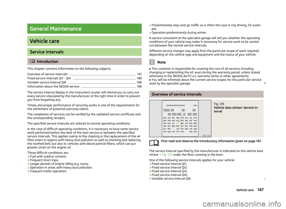
Fig. 129
Vehicle data sticker: Service in-
terval
First read and observe the introductory information given on page 147.
The service interval specified by the manufacturer is indicated on the vehicle data sticker » Fig. 129 under the floor covering in the boot.
One of the following service intervals applies for your vehicle: › Fixed service interval QI1;
› Fixed service interval QI2;
› Fixed service interval QI3;
› Fixed service interval QI4;
› Variable service interval QI6.
147Vehicle care
Page 161 of 226
Natural leatherFirst read and observe the introductory information and safety warn-
ings
on page 157.
Leather is a natural material with specific properties, and requires regular clean-
ing and maintenance.
The leather should be cleaned on a regular basis depending on the amount of
wear-and-tear.
Dust and dirt in the pores and folds act as abrasive materials. This leads to severe corrosion and the premature brittleness of the leather surface.
We recommend that you remove dust regularly and at short intervals using a
cloth or vacuum cleaner.
Clean soiled leather surfaces with a water-dampened cotton or woollen cloth and
then dry with a clean, dry cloth »
.
Clean severely soiled areas with a cloth soaked in a mild soap solution (2 table-
spoons of neutral soap to 1 litre of water).
To remove stains , use a cleaning agent specially designed for this purpose.
Treat the leather regularly and at suitable intervals using a suitable leather care
product.
CAUTION
■ Ensure that no part of the leather is soaked through during cleaning and that
no water gets into the seams. Otherwise, the leather could become brittle or
cracked.■
Avoid leaving the vehicle for lengthy periods in bright sunlight to avoid the
leather from bleaching. If the vehicle is parked in the open for lengthy periods, protect the leather from direct sunlight by covering it.
■
Sharp-edged objects on items of clothing such as zip fasteners, rivets, sharp-
edged belts, jewellery and pendants may leave permanent scratches or signs of
rubbing on the surface. Such damage cannot be subsequently recognised as a
justified complaint.
■
The use of a mechanical steering wheel lock may damage the leather surface of
the steering wheel.
■ Use a care cream with light blocker and impregnation effect on a regular basis
and each time after cleaning. The cream nourishes the leather, allows it to
breathe and keeps it supple and also provides moisture. It also creates surface
protection.■
Some clothing materials, e.g. dark denim, do not have sufficient colour fastness.
This can cause damage or clearly visible discolouration to seat covers, even when used correctly. This applies particularly to light-coloured seat covers. This does
not relate to a fault in the seat cover, but rather to poor colour fastness of the
clothing textiles.
Note
When using the vehicle, minor visible changes may occur to the leather parts of
the covers (e.g. wrinkles or creases) as a result of the stress applied to the covers.
Artificial leather, cloths and Alcantara ®
First read and observe the introductory information and safety warn- ings
on page 157.
Artificial leather
Clean artificial leather with a damp cloth.
If this method does not completely clean the artificial leather, use a mild soap sol- ution or cleaning products specially designed for this purpose.
Fabric
Clean upholstery cover materials and cloth trims on doors, boot cover, etc. using
specific cleaning agents, e.g., dry foam.
Use a soft sponge, brush, or commercially available microfibre cloth.
Use a cloth and a cleaning agent specifically designed for this purpose to clean
the roof trim.
Remove any lumps on the cover fabric and any fabric residue using a brush.
Remove stubborn hair using a “cleaning glove”.
Alcantara ®
Dust and fine dirt particles in pores, creases and seams may chafe and damage the surface.
If you leave your vehicle parked in the open for lengthy periods, protect the Al-
cantara ®
seat covers from the direct rays of the sun to prevent fading.
158General Maintenance
Page 182 of 226
WARNING■When the warning light illuminates, immediately reduce the speed and
avoid sudden steering and brake manoeuvres. Stop the vehicle as soon as
possible and inspect the tyres and their inflation pressure.■
Under certain circumstances (e.g. sporty style of driving, wintry or unpaved
roads) the warning light may light up after a delay, or not at all.
CAUTION
■
The tyre control display does therefore not replace the regular tyre inflation
pressure control, as the system cannot detect an even loss of pressure.■
The system cannot warn in case of very rapid tyre inflation pressure loss, e.g. in
case of sudden tyre damage. In this case carefully bring the vehicle to a standstill
without sudden steering movements or sharp braking.
■
To ensure a proper functioning of the tyre control display, it is necessary to re-
peat the basic setting every 10,000 km or once a year.
Spare wheel
Fig. 144
Boot: Spare wheel
First read and observe the introductory information and safety warn-
ings on page 175.
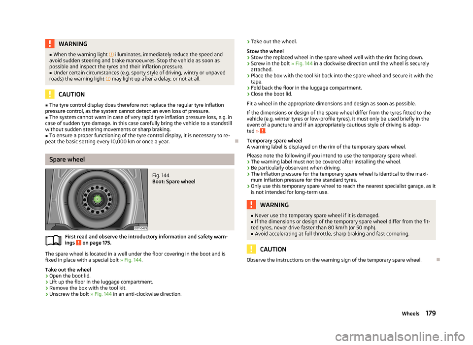
The spare wheel is located in a well under the floor covering in the boot and is
fixed in place with a special bolt » Fig. 144.
Take out the wheel
›
Open the boot lid.
›
Lift up the floor in the luggage compartment.
›
Remove the box with the tool kit.
›
Unscrew the bolt » Fig. 144 in an anti-clockwise direction.
›Take out the wheel.
Stow the wheel›
Stow the replaced wheel in the spare wheel well with the rim facing down.
›
Screw in the bolt » Fig. 144 in a clockwise direction until the wheel is securely
attached.
›
Place the box with the tool kit back into the spare wheel and secure it with the
tape.
›
Fold back the floor in the luggage compartment.
›
Close the boot lid.
Fit a wheel in the appropriate dimensions and design as soon as possible.
If the dimensions or design of the spare wheel differ from the tyres fitted to the
vehicle (e.g. winter tyres or low-profile tyres), it must only be used briefly in the
event of a puncture and if an appropriately cautious style of driving is adop-
ted »
.
Temporary spare wheel
A warning label is displayed on the rim of the temporary spare wheel.
Please note the following if you intend to use the temporary spare wheel. › The warning label must not be covered after installing the wheel.
› Be particularly observant when driving.
› The inflation pressure for the temporary spare wheel is identical to the maxi-
mum inflation pressure for the standard tyres.
› Only use this temporary spare wheel to reach the nearest specialist garage, as it
is not intended for long-term use.
WARNING■ Never use the temporary spare wheel if it is damaged.■If the dimensions or design of the temporary spare wheel differ from the fit-
ted tyres, never drive faster than 80 km/h (or 50 mph).■
Avoid accelerating at full throttle, sharp braking and fast cornering.
CAUTION
Observe the instructions on the warning sign of the temporary spare wheel.
179Wheels
Page 185 of 226
Do-it-yourself
Emergency equipment and self-help
Emergency equipment
Introduction
This chapter contains information on the following subjects:
First aid kit and warning triangle
182
fire extinguisher
183
Vehicle tool kit
183
First aid kit and warning triangle
Fig. 146
Placing of the first-aid kit: Rapid / Rapid Spaceback
Fig. 147
Placing of the warning triangle: Rapid / Rapid Spaceback
First read and observe the introductory information given on page 182.
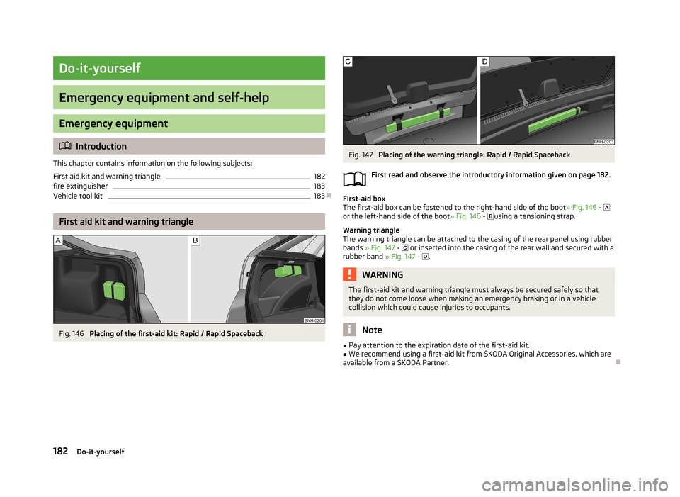
First-aid box
The first-aid box can be fastened to the right-hand side of the boot » Fig. 146 -
or the left-hand side of the boot » Fig. 146 -
using a tensioning strap.
Warning triangle
The warning triangle can be attached to the casing of the rear panel using rubber bands » Fig. 147 -
or inserted into the casing of the rear wall and secured with a
rubber band » Fig. 147 -
.
WARNINGThe first-aid kit and warning triangle must always be secured safely so that
they do not come loose when making an emergency braking or in a vehicle
collision which could cause injuries to occupants.
Note
■ Pay attention to the expiration date of the first-aid kit.■We recommend using a first-aid kit from ŠKODA Original Accessories, which are
available from a ŠKODA Partner.
182Do-it-yourself
Page 187 of 226
WARNING■The factory-supplied lifting jack is only intended for your model of vehicle.
Under no circumstances use it to lift heavier vehicles or other loads – risk of
injury!■
Ensure that the vehicle tool kit is safely secured in the boot.
■
Ensure that the box is always secured with the strap.
Changing a wheel
Introduction
This chapter contains information on the following subjects:
Preliminary work
184
Changing a wheel
185
Follow-up work
185
Loosening/tightening wheel bolts
185
Raising the vehicle
186
Securing wheels against theft
186WARNING■ If you are in flowing traffic, switch on the hazard warning light system and
set up the warning triangle at the prescribed distance! The national legal re-
quirements must be observed.■
Park the vehicle as far away as possible from the flow of traffic. Park on as
flat and firm a surface as possible.
■
The following instructions must be followed if the vehicle is subsequently
fitted with tyres or rims that differ from the factory-fitted ones » page 177,
New tyres .
WARNINGObserve the following instructions for lifting the vehicle.■If the wheel has to be changed on a slope, first of all block the opposite
wheel with a stone or similar object to prevent the vehicle from unexpectedly
rolling away.■
Secure the base plate of the lifting jack with suitable means to prevent pos-
sible moving. A soft and slippery ground under the base plate may move the lifting jack, causing the vehicle to fall down. It is therefore always necessary to
place the lifting jack on a solid surface or use a wide and stable base. Use a non-slip base (e.g. a rubber foot mat) if the surface is smooth, such as cobbled
stones, tiled floor, etc.
■
Only attach the lifting jack to the attachment points provided for this pur-
pose.
■
Always raise the vehicle with the doors closed.
■
Never position any body parts, such as arms or legs under the vehicle, while
the vehicle is raised with a lifting jack.
■
Never start the engine when the vehicle is raised – risk of injury.
CAUTION
■ The prescribed tightening torque of the wheel bolts for steel and light alloy
wheels is 120 Nm.■
If the wheel bolts are fastened too tightly, this can cause damage to the anti-
theft wheel bolt or the adapter.
Note
The national legal requirements must be observed when changing a wheel.
Preliminary work
First read and observe the introductory information and safety warn-ings
on page 184.
Always change a wheel on a level surface as far as possible.
The following steps must be carried out before actually changing the wheel:
›
Have all of the occupants get out of the vehicle. While changing a tyre, the oc-
cupants of the vehicle should not stand on the road (they should instead remain
behind a crash barrier).
184Do-it-yourself
Page 188 of 226
›Switch off the engine.›Move the gearshift lever into
Neutral or move the selector lever for the auto-
matic gearbox into position P .›
Firmly apply the handbrake.
›
Uncouple any trailers.
›
Remove the vehicle tool kit » page 183 and the spare wheel » page 179 from
the boot.
Changing a wheel
First read and observe the introductory information and safety warn-
ings
on page 184.
›
Remove the full wheel trim » page 180 or caps » page 180 .
›
First of all slacken the anti-theft wheel bolt and then the other wheel
bolts » page 185 .
›
Jack up the vehicle until the wheel that needs changing is clear of the
ground » page 186 .
›
Unscrew the wheel bolts and place them on a clean surface (cloth, paper, etc.).
›
Remove the wheel carefully.
›
Attach the spare wheel and slightly screw on the wheel bolts.
›
Lower the vehicle.
›
Alternately tighten wheel bolts opposite (diagonally) with the wheel wrench.
Tighten the anti-theft wheel bolt last » page 185.
›
Replace the wheel trim or the caps.
Note
■
All bolts must be clean and must turn easily.■Under no circumstances grease or oil the wheel bolts!■
When fitting unidirectional tyres, ensure that the direction of rotation is cor-
rect » page 178 .
Follow-up work
First read and observe the introductory information and safety warn-
ings
on page 184.
The following steps must also be performed after changing the wheel.
› Stow and attach the replaced wheel in the spare wheel well using a special
bolt » page 179 , Spare wheel .›
Stow the tool kit in the space provided and secure using the band.
›
Check the tyre pressure on the installed spare wheel as soon as possible.
›
Have the tightening torque of the wheel bolts checked with a torque wrench
as soon as possible.
›
Replace the damaged wheel or consult a specialist garage about repair options.
Note
■ If it is determined that the wheel bolts are corroded and difficult to turn when
changing the wheel, the bolts must be replaced before checking the tightening
torque.■
Drive cautiously and only at a moderate speed until the tightening torque has
been checked.
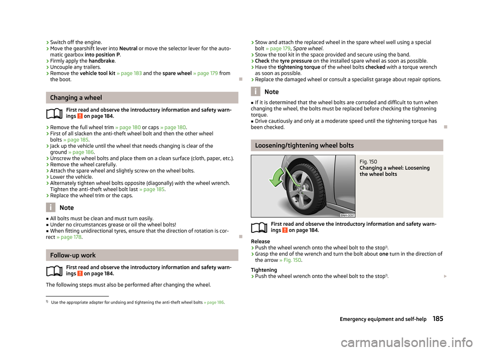
Loosening/tightening wheel bolts
Fig. 150
Changing a wheel: Loosening
the wheel bolts
First read and observe the introductory information and safety warn- ings on page 184.
Release
›
Push the wheel wrench onto the wheel bolt to the stop 1)
.
›
Grasp the end of the wrench and turn the bolt about one turn in the direction of
the arrow » Fig. 150.
Tightening
›
Push the wheel wrench onto the wheel bolt to the stop 1)
.
1)
Use the appropriate adapter for undoing and tightening the anti-theft wheel bolts
» page 186.
185Emergency equipment and self-help
Page 191 of 226
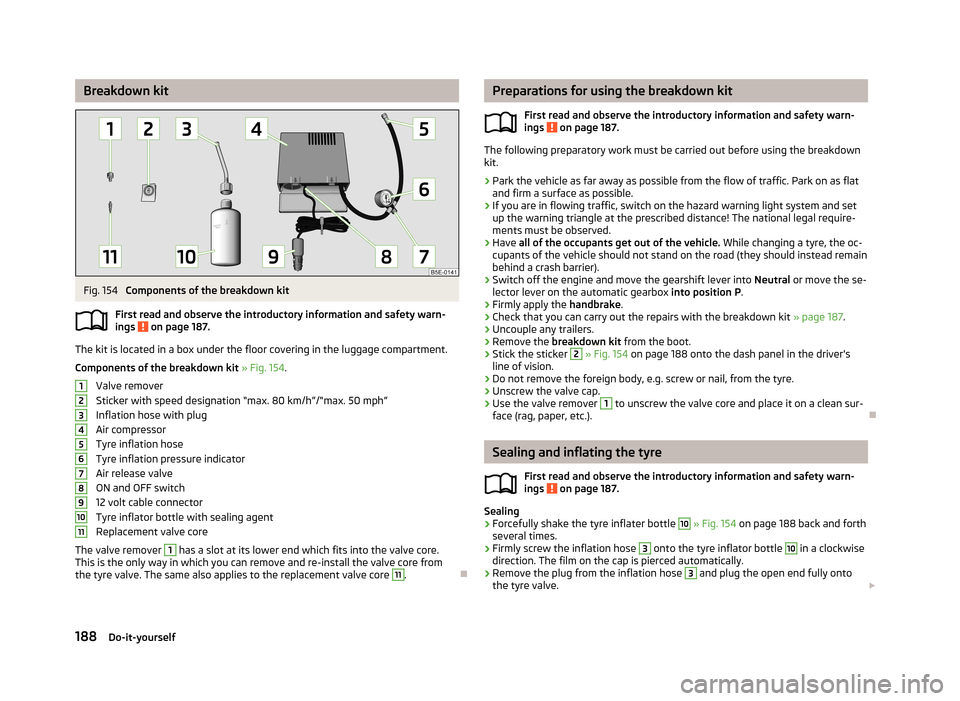
Breakdown kitFig. 154
Components of the breakdown kit
First read and observe the introductory information and safety warn-
ings
on page 187.
The kit is located in a box under the floor covering in the luggage compartment.
Components of the breakdown kit » Fig. 154 .
Valve remover
Sticker with speed designation “max. 80 km/h”/“max. 50 mph”
Inflation hose with plug
Air compressor
Tyre inflation hose
Tyre inflation pressure indicator
Air release valve
ON and OFF switch
12 volt cable connector
Tyre inflator bottle with sealing agent
Replacement valve core
The valve remover
1
has a slot at its lower end which fits into the valve core.
This is the only way in which you can remove and re-install the valve core from
the tyre valve. The same also applies to the replacement valve core
11
.
1234567891011Preparations for using the breakdown kit
First read and observe the introductory information and safety warn-
ings
on page 187.
The following preparatory work must be carried out before using the breakdown kit.
›
Park the vehicle as far away as possible from the flow of traffic. Park on as flat and firm a surface as possible.
›
If you are in flowing traffic, switch on the hazard warning light system and setup the warning triangle at the prescribed distance! The national legal require-
ments must be observed.
›
Have all of the occupants get out of the vehicle. While changing a tyre, the oc-
cupants of the vehicle should not stand on the road (they should instead remain
behind a crash barrier).
›
Switch off the engine and move the gearshift lever into Neutral or move the se-
lector lever on the automatic gearbox into position P.
›
Firmly apply the handbrake.
›
Check that you can carry out the repairs with the breakdown kit » page 187.
›
Uncouple any trailers.
›
Remove the breakdown kit from the boot.
›
Stick the sticker
2
» Fig. 154 on page 188 onto the dash panel in the driver's
line of vision.
›
Do not remove the foreign body, e.g. screw or nail, from the tyre.
›
Unscrew the valve cap.
›
Use the valve remover
1
to unscrew the valve core and place it on a clean sur-
face (rag, paper, etc.).
Sealing and inflating the tyre
First read and observe the introductory information and safety warn-
ings
on page 187.
Sealing
›
Forcefully shake the tyre inflater bottle
10
» Fig. 154 on page 188 back and forth
several times.
›
Firmly screw the inflation hose
3
onto the tyre inflator bottle
10
in a clockwise
direction. The film on the cap is pierced automatically.
›
Remove the plug from the inflation hose
3
and plug the open end fully onto
the tyre valve.
188Do-it-yourself