headlights SKODA RAPID 2013 1.G Owner's Manual
[x] Cancel search | Manufacturer: SKODA, Model Year: 2013, Model line: RAPID, Model: SKODA RAPID 2013 1.GPages: 226, PDF Size: 15.16 MB
Page 15 of 226
Cold range
If the pointer is still in the left area of the scale, this indicates that the engine has not yet reached its operating temperature. Avoid high speeds, full throttle and
high engine loads. This prevents possible damage to the engine.
The operating range
The engine has reached its operating temperature as soon as the pointer moves into the mid-range of the scale. At very high ambient temperatures or heavy en- gine loads, the pointer may move even further to the right.
High temperature range
If the pointer reaches the red area of the scale, the coolant temperature is too high. Further information » page 16, Coolant .
CAUTION
Additional headlights and other attached components in front of the air inlet im-
pair the cooling efficiency of the coolant.
Fuel gauge
Fig. 5
Fuel gauge
First read and observe the introductory information and safety warn-
ings
on page 10.
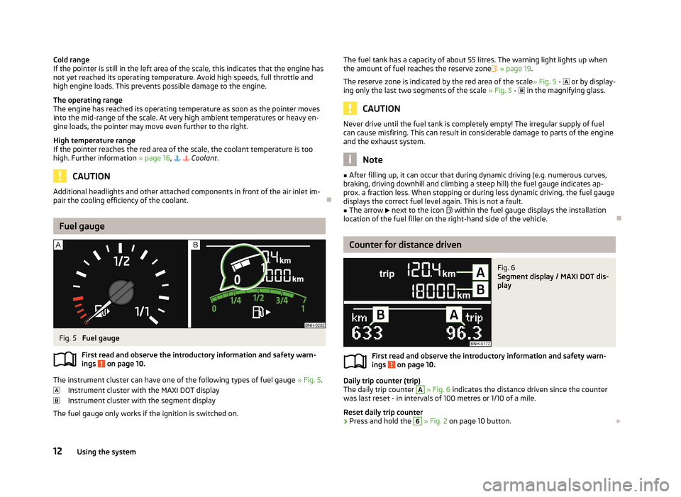
The instrument cluster can have one of the following types of fuel gauge » Fig. 5.
Instrument cluster with the MAXI DOT display
Instrument cluster with the segment display
The fuel gauge only works if the ignition is switched on.
The fuel tank has a capacity of about 55 litres. The warning light lights up when the amount of fuel reaches the reserve zone » page 19 .
The reserve zone is indicated by the red area of the scale » Fig. 5 - or by display-
ing only the last two segments of the scale » Fig. 5 - in the magnifying glass.
CAUTION
Never drive until the fuel tank is completely empty! The irregular supply of fuel
can cause misfiring. This can result in considerable damage to parts of the engine
and the exhaust system.
Note
■ After filling up, it can occur that during dynamic driving (e.g. numerous curves,
braking, driving downhill and climbing a steep hill) the fuel gauge indicates ap-
prox. a fraction less. When stopping or during less dynamic driving, the fuel gauge displays the correct fuel level again. This is not a fault.■
The arrow next to the icon within the fuel gauge displays the installation
location of the fuel filler on the right-hand side of the vehicle.
Counter for distance driven
Fig. 6
Segment display / MAXI DOT dis-
play
First read and observe the introductory information and safety warn-
ings on page 10.
Daily trip counter (trip)
The daily trip counter
A
» Fig. 6 indicates the distance driven since the counter
was last reset - in intervals of 100 metres or 1/10 of a mile.
Reset daily trip counter
›
Press and hold the
6
» Fig. 2 on page 10 button.
12Using the system
Page 44 of 226
Lights and visibility
Lights
Introduction
This chapter contains information on the following subjects:
Parking light and low beam
41
Daytime running lights(DAY LIGHT)
42
Turn signal and main beam
43
Fog lights
43
Fog lights with CORNER function
43
Rear fog light
44
Hazard warning light system
44
Parking light
45
Unless otherwise stated, the lights only work when the ignition is switched on.
On models fitted with right-hand steering, the position of some of the controls
differs from that shown in » Fig. 21 on page 41. The symbols which mark the po-
sitions of the controls are identical.
WARNING■ The activation of the lights should only be undertaken in accordance with
national legal requirements.■
The driver is always responsible for the correct settings and use of the
lights.
■
Never drive with only the side lights on! The side lights are not bright
enough to light up the road sufficiently in front of you or to be seen by other oncoming traffic. Therefore always switch on the low beam when it is dark or if visibility is poor.
NoteThe headlights may mist up temporarily. When the driving lights are switched on,
the light outlet surfaces are free from mist after a short period, although the
headlight lenses may still be misted up in the peripheral areas. This mist has no
influence on the life of the lighting system.
Parking light and low beam
Fig. 21
Light switch and control dial for
headlight range adjustment
First read and observe the introductory information and safety warn-
ings on page 41.
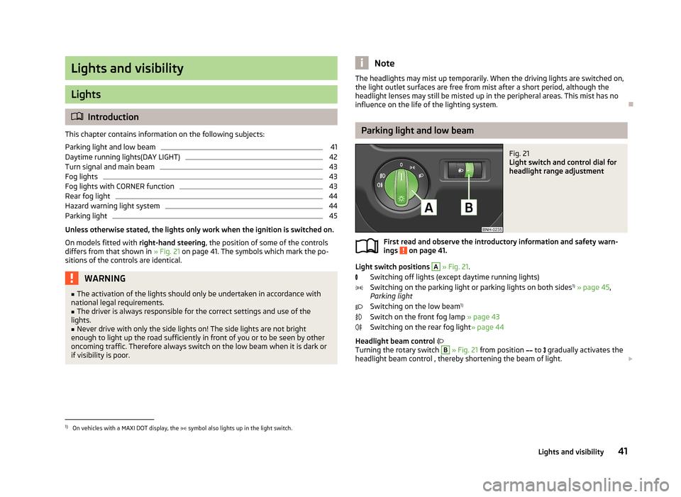
Light switch positions
A
» Fig. 21 .
Switching off lights (except daytime running lights) Switching on the parking light or parking lights on both sides 1)
» page 45 ,
Parking light
Switching on the low beam 1)
Switch on the front fog lamp » page 43
Switching on the rear fog light » page 44
Headlight beam control
Turning the rotary switch
B
» Fig. 21 from position
to
gradually activates the
headlight beam control , thereby shortening the beam of light.
1)
On vehicles with a MAXI DOT display, the
symbol also lights up in the light switch.
41Lights and visibility
Page 52 of 226
Activating the windscreen wipers and washersFig. 32
Operating lever: Windscreen
wipers and washer settings
First read and observe the introductory information and safety warn-
ings on page 48.
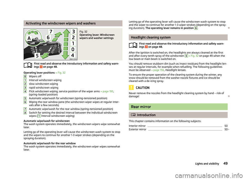
Operating lever positions » Fig. 32
Wipers off
Interval windscreen wiping
slow windscreen wiping
rapid windscreen wiping
Flick windscreen wiping, service position of the wiper arms » page 195,
(spring-loaded position)
Automatic wipe/wash for windscreen (spring-tensioned position) Wiping the rear window pane (the windscreen wiper wipes at regular inter- vals after a few seconds)
Automatic wipe/wash for the rear window (spring-tensioned position)
Switch for setting the desired interval between the individual windscreen wipes (
1
Interval windscreen wiping)
Automatic wipe/wash for windscreen
The wash system operates immediately, the windscreen wipers wipe somewhat
later.
Letting go of the operating lever will cause the windscreen wash system to stop
and the wipers to continue for another 1-3 wiper strokes (depending on the
spraying duration).
Automatic wipe/wash for the rear window The wash system operates immediately, the windscreen wiper wipes somewhatlater.
01234567ALetting go of the operating lever will cause the windscreen wash system to stop
and the wiper to continue for another 1-3 wiper strokes (depending on the spray-
ing duration). The operating lever remains in position 6
.
Headlight cleaning system
First read and observe the introductory information and safety warn-
ings
on page 48.
After the ignition is switched on, the headlights are always cleaned at the first
and after every tenth spray of the windscreen
5
» Fig. 32 on page 49 when the
low beam or main beam is switched on.
You should remove stubborn dirt (such as insect residues) from the headlight len-
ses at regular intervals, for example when refuelling. The following guidelines
must be observed » page 156, Headlight lenses .
To ensure the proper operation of the cleaning system during the winter, any
snow should be removed from the washer nozzle fixtures and ice should be
cleared with a de-icing spray.
CAUTION
Never remove the nozzles from the headlight cleaning system by hand – risk of
damage!
Rear mirror
Introduction
This chapter contains information on the following subjects:
Interior mirror
50
Exterior mirror
50
49Lights and visibility
Page 113 of 226
NoteAfter driving through water, we recommend having the vehicle checked by a spe-
cialist garage.
Driving abroad
Introduction
This chapter contains information on the following subjects:
Unleaded petrol
110
Headlights
110
In certain countries, it may be possible that the ŠKODA Service Partner network is
limited or has not been established. This is the reason why procuring certain
spare parts may be somewhat complicated and specialist garages may only be
able to make limited repairs.
Unleaded petrol
First read and observe the introductory information given on page 110.
A vehicle fitted with a petrol engine must always be refuelled with unleaded pet-rol » page 161 , Unleaded petrol . Information regarding the locations of filling sta-
tions that offer unleaded petrol is, for example, provided by the automobile asso-
ciations.
Headlights
First read and observe the introductory information given on page 110.
The low beam of your headlights is set asymmetrically. It illuminates the side of
the road on which the vehicle is being driven to a greater extent.
When driving in countries in which the traffic drives on the other side of the roadthan in your home country, the asymmetrical low beam may dazzle oncoming
drivers. In order to avoid this, the headlights must be adjusted at a specialist ga-
rage.
NoteYou can find out more information on adjusting the headlights at a specialist ga-
rage.
110Driving
Page 127 of 226
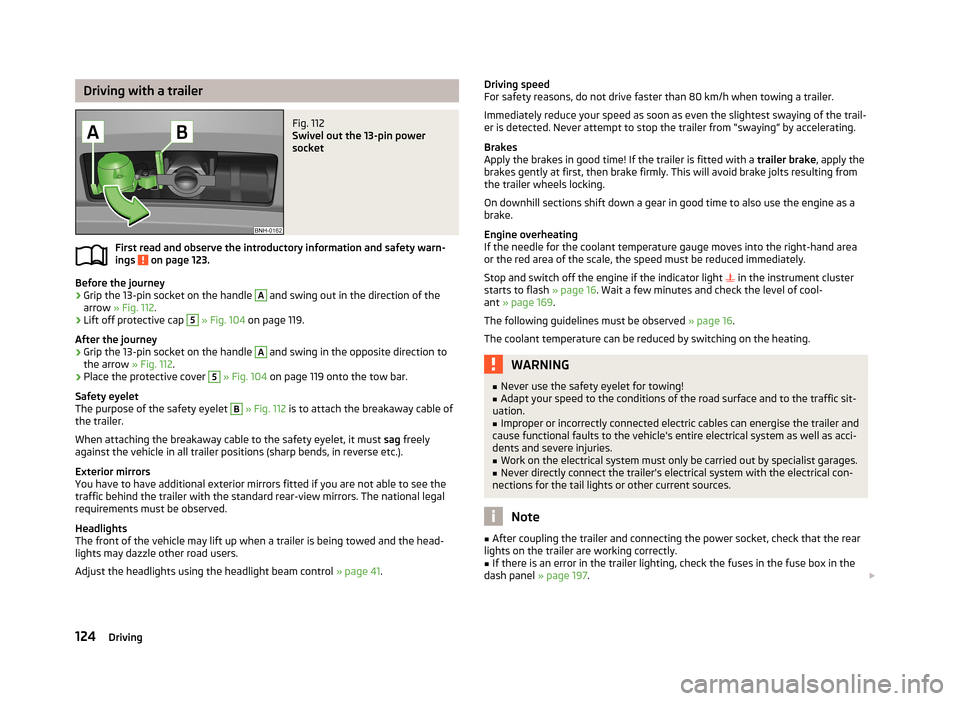
Driving with a trailerFig. 112
Swivel out the 13-pin power
socket
First read and observe the introductory information and safety warn-
ings on page 123.
Before the journey
›
Grip the 13-pin socket on the handle
A
and swing out in the direction of the
arrow » Fig. 112 .
›
Lift off protective cap
5
» Fig. 104 on page 119.
After the journey
›
Grip the 13-pin socket on the handle
A
and swing in the opposite direction to
the arrow » Fig. 112.
›
Place the protective cover
5
» Fig. 104 on page 119 onto the tow bar.
Safety eyelet
The purpose of the safety eyelet
B
» Fig. 112 is to attach the breakaway cable of
the trailer.
When attaching the breakaway cable to the safety eyelet, it must sag freely
against the vehicle in all trailer positions (sharp bends, in reverse etc.).
Exterior mirrors
You have to have additional exterior mirrors fitted if you are not able to see the
traffic behind the trailer with the standard rear-view mirrors. The national legal requirements must be observed.
Headlights
The front of the vehicle may lift up when a trailer is being towed and the head-
lights may dazzle other road users.
Adjust the headlights using the headlight beam control » page 41.
Driving speed
For safety reasons, do not drive faster than 80 km/h when towing a trailer.
Immediately reduce your speed as soon as even the slightest swaying of the trail-
er is detected. Never attempt to stop the trailer from “swaying” by accelerating.
Brakes
Apply the brakes in good time! If the trailer is fitted with a trailer brake, apply the
brakes gently at first, then brake firmly. This will avoid brake jolts resulting from
the trailer wheels locking.
On downhill sections shift down a gear in good time to also use the engine as a brake.
Engine overheating
If the needle for the coolant temperature gauge moves into the right-hand area
or the red area of the scale, the speed must be reduced immediately.
Stop and switch off the engine if the indicator light
in the instrument cluster
starts to flash » page 16. Wait a few minutes and check the level of cool-
ant » page 169 .
The following guidelines must be observed » page 16.
The coolant temperature can be reduced by switching on the heating.WARNING■ Never use the safety eyelet for towing!■Adapt your speed to the conditions of the road surface and to the traffic sit-
uation.■
Improper or incorrectly connected electric cables can energise the trailer and
cause functional faults to the vehicle's entire electrical system as well as acci-
dents and severe injuries.
■
Work on the electrical system must only be carried out by specialist garages.
■
Never directly connect the trailer's electrical system with the electrical con-
nections for the tail lights or other current sources.
Note
■ After coupling the trailer and connecting the power socket, check that the rear
lights on the trailer are working correctly.■
If there is an error in the trailer lighting, check the fuses in the fuse box in the
dash panel » page 197.
124Driving
Page 159 of 226
When drying the windows after washing the vehicle, do not use window leathers
that have been used to polish the bodywork. Residues of preservatives in the
window leather can make the window dirty and reduce visibility.
CAUTION
■ The ice scraper should not be moved forward and backward but in one direction
to avoid any damage to the surface of the glass.■
Snow or ice that is contaminated with coarse dirt such as fine gravel, sand or
salt must not be removed from the windows and mirrors – there is a risk of dam-
age to the surface of the windows and mirrors.
■
Do not remove snow or ice from glass parts using warm or hot water – risk of
cracks forming in the glass.
■
When removing snow or ice from windows and mirror lenses ensure that the
paintwork of the vehicle is not to damage.
■
Do not clean the inside of the windows with sharp-edged objects or corrosive
and acidic cleaning agents – there is a risk of damaging the heating elements or
window aerial.
Headlight lenses
First read and observe the introductory information and safety warn-ings
on page 153.
Clean plastic front headlight lenses using clean, warm water and soap.
CAUTION
■ Never wipe headlights with a dry cloth.■Do not use any sharp objects to clean the plastic lenses, as this may damage
the protective paintwork and consequently cause cracks to form on the headlight
lenses.■
Do not use any harsh cleaning products or chemical solvents to clean the head-
lights, as this could damage the headlight lenses.
Door lock cylinders
First read and observe the introductory information and safety warn-
ings
on page 153.
Specific products must be used for de-icing door lock cylinders.
CAUTIONWhen washing your vehicle, ensure as little water as possible gets into the lock-
ing cylinders.
Cavity protection
First read and observe the introductory information and safety warn-
ings
on page 153.
All the cavities of your vehicle which are at risk from corrosion are protected for
life by a layer of protective wax applied in the factory.
This wax protection does not need to be inspected or re-applied. If any small amount of wax flow out of the cavities at high temperatures, thesemust be removed with a plastic scraper and the stains cleaned using a petroleum
cleaner.
WARNINGSafety regulations should be observed when using petroleum cleaner to re-
move wax – risk of fire!
Wheels
First read and observe the introductory information and safety warn-
ings
on page 153.
Wheel rims
Also thoroughly wash the wheel rims when washing the vehicle on a regular ba-
sis.
Regularly remove salt and brake abrasion, otherwise the rim material will be cor-
roded.
Damage to the paint layer on the wheel rims must be touched up immediately.
Light alloy wheels
After washing thoroughly and treat the wheel rims with a protective product for
light alloy wheels. Products which cause abrasion must not be used to treat the
wheel rims.
156General Maintenance
Page 169 of 226
The filling level of the container is about 3.5 litres and about 5.4 litres on vehicles
that have a headlight washing system 1)
.
Clear water is not sufficient to intensively clean the windscreen and headlights. We recommend using clean water together with a screen cleaner from the range
of ŠKODA Original Accessories (with antifreeze in winter), which will remove any
stubborn dirt.
In Winter, the washing water should always be mixed with antifreeze even if the
vehicle has heated windscreen washer nozzles.
Under exceptional circumstances, methylated spirits can also be used if no screen
cleaner with antifreeze is available. The concentration of methylated spirits must
not be more than 15 %. The freeze protection at this concentration is sufficient
only to -5 °C.
CAUTION
■ Under no circumstances must radiator antifreeze or other additives be added to
the windscreen washer fluid.■
If the vehicle is fitted with a headlight cleaning system, only cleaning products
which do not attack the polycarbonate coating of the headlights must be added
to the windscreen washer fluid.
■
Do not remove the filter from the windscreen washer fluid reservoir when refill-
ing, as this may cause contamination of the liquid transportation system, leading
in turn to a windscreen washer system malfunction.
Engine oil
Introduction
This chapter contains information on the following subjects:
Specifications and capacity
167
Checking the oil level
167
Replenishing
168
Changing
168
The engine has been factory-filled with a high-grade oil that can be use through-
out the year - except in extreme climate zones.
The engine oils are undergoing continuous further development. Thus the infor-
mation stated in this Owner's Manual is only correct at the time of publication.
ŠKODA Service Partners are informed about the latest changes by the manufac-
turer. We therefore recommend that the oil change be completed by a ŠKODA
Service Partner.
The specifications (VW standards) stated in the following can be indicated sepa-
rately or together with other specifications on the bottle.
The oil capacities include oil filter change. Check the oil level when filling; do not
over fill. The oil level must be between the markings » page 167.WARNING■
The engine compartment of your car is a hazardous area. The following
warning instructions must be followed at all times when working in the en-
gine compartment » page 162.■
Do not continue your journey if for some reason it is not possible to top up
the engine oil ! Switch off the engine and seek assistance from a specialist
garage.
■
If the oil level is above level
A
» Fig. 136 on page 167, do not continue to
drive! Switch off the engine and seek assistance from a specialist garage.
CAUTION
Do not pour any additives into the engine oil – risk of serious damage to the en-
gine parts!
Note
■ Before a long drive we recommend that you purchase and carry with you engine
oil which complies with the specification for your vehicle.■
We recommend that you use oils from ŠKODA Original Accessories.
■
If your skin has come into contact with oil, it must be washed thoroughly.
1)
In some countries, 5.4 l. applies for both variants.
166General Maintenance
Page 203 of 226
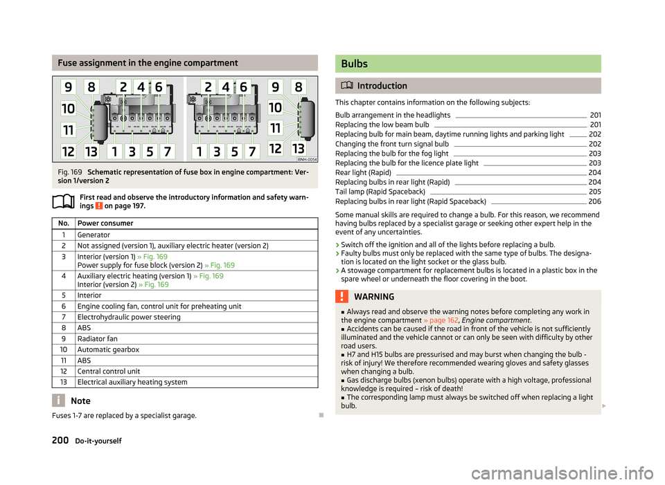
Fuse assignment in the engine compartmentFig. 169
Schematic representation of fuse box in engine compartment: Ver-
sion 1/version 2
First read and observe the introductory information and safety warn-
ings
on page 197.
No.Power consumer1Generator2Not assigned (version 1), auxiliary electric heater (version 2)3Interior (version 1) » Fig. 169
Power supply for fuse block (version 2) » Fig. 1694Auxiliary electric heating (version 1) » Fig. 169
Interior (version 2) » Fig. 1695Interior6Engine cooling fan, control unit for preheating unit7Electrohydraulic power steering8ABS9Radiator fan10Automatic gearbox11ABS12Central control unit13Electrical auxiliary heating system
Note
Fuses 1-7 are replaced by a specialist garage.
Bulbs
Introduction
This chapter contains information on the following subjects:
Bulb arrangement in the headlights
201
Replacing the low beam bulb
201
Replacing bulb for main beam, daytime running lights and parking light
202
Changing the front turn signal bulb
202
Replacing the bulb for the fog light
203
Replacing the bulb for the licence plate light
203
Rear light (Rapid)
204
Replacing bulbs in rear light (Rapid)
204
Tail lamp (Rapid Spaceback)
205
Replacing bulbs in rear light (Rapid Spaceback)
206
Some manual skills are required to change a bulb. For this reason, we recommend
having bulbs replaced by a specialist garage or seeking other expert help in the
event of any uncertainties.
› Switch off the ignition and all of the lights before replacing a bulb.
› Faulty bulbs must only be replaced with the same type of bulbs. The designa-
tion is located on the light socket or the glass bulb.
› A stowage compartment for replacement bulbs is located in a plastic box in the
spare wheel or underneath the floor covering in the boot.
WARNING■ Always read and observe the warning notes before completing any work in
the engine compartment » page 162, Engine compartment .■
Accidents can be caused if the road in front of the vehicle is not sufficiently
illuminated and the vehicle cannot or can only be seen with difficulty by other
road users.
■
H7 and H15 bulbs are pressurised and may burst when changing the bulb -
risk of injury! We therefore recommended wearing gloves and safety glasses
when changing a bulb.
■
Gas discharge bulbs (xenon bulbs) operate with a high voltage, professional
knowledge is required – risk of death!
■
The corresponding lamp must always be switched off when replacing a light
bulb.
200Do-it-yourself
Page 204 of 226
CAUTIONDo not take hold of the glass bulb with naked fingers (even the smallest amountof dirt reduces the working life of the light bulb). Use a clean cloth, napkin, or sim-
ilar.
Note
■ This Owner's Manual only describes the replacement of bulbs where it is possi-
ble to replace the bulbs on your own without any complications arising. Other bulbs must be replaced by a specialist garage.■
We recommend that a box of replacement bulbs always be carried in the vehi-
cle. Replacement bulbs can be purchased from ŠKODAOriginal Accessories.
■
We recommend having the headlight settings checked by a specialist garage af-
ter replacing a bulb in the main, low or fog beam.
■
Consult a specialist garage in the event of a failure in a xenon gas discharge
lamp.
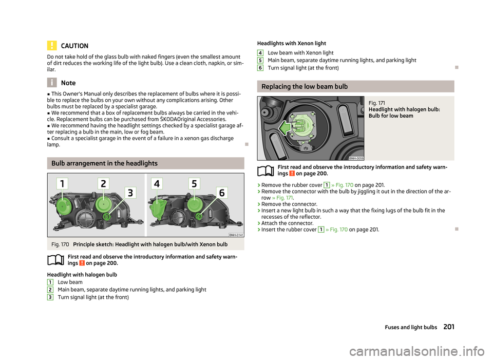
Bulb arrangement in the headlights
Fig. 170
Principle sketch: Headlight with halogen bulb/with Xenon bulb
First read and observe the introductory information and safety warn- ings
on page 200.
Headlight with halogen bulb
Low beam
Main beam, separate daytime running lights, and parking light
Turn signal light (at the front)
123Headlights with Xenon light
Low beam with Xenon light
Main beam, separate daytime running lights, and parking light
Turn signal light (at the front)
Replacing the low beam bulb
Fig. 171
Headlight with halogen bulb:
Bulb for low beam
First read and observe the introductory information and safety warn- ings on page 200.
›
Remove the rubber cover
1
» Fig. 170 on page 201.
›
Remove the connector with the bulb by jiggling it out in the direction of the ar-
row » Fig. 171 .
›
Remove the connector.
›
Insert a new light bulb in such a way that the fixing lugs of the bulb fit in the
recesses of the reflector.
›
Attach the connector.
›
Insert the rubber cover
1
» Fig. 170 on page 201.
456201Fuses and light bulbs
Page 218 of 226
Fuel reserveIndicator light19
Fuses Assignment
197
Assignment of fuses in the dash panel198
Colour coding197
Fuse assignment in the engine compartment200
Replacing197
Fuses in the engine compartment Assignment
200
G
Gearbox Information messages
13
Gear change Gear recommendation
24
Information on the selected gear24
Gear changing Gear stick
101
General view Cockpit
9
Generator Indicator light
15
Glasses storage box62
Glow plug system Warning light
18
GSM85
H
Handbrake
100
Indicator light14
Hazard warning light system44
HBA112
Head airbag139
Headlight cleaning system Headlight cleaning system
49
HeadlightsBulb arrangement201
Driving abroad110
Headlight cleaning system49
Head restraint53
Heating Defrosting windows
78
Exterior mirror50
operating77
Rear window47
Recirculated air mode79
Seats54
Heating and air-conditioning76
Heating rear window47
HHC112
Hill Hold Control (HHC)112
Hooks66
Horn9
Hydraulic Brake Assist (HBA)112
I
Ice-scraper
155
Ice warning23
Ignition98
Immobiliser98
Indicator lights14
Individual settings Locking
34
Unlocking34
Inertia reels133
Information system22
Compass point display24
Door warning24
Gear recommendation24
Ice warning23
MAXI DOT display27
Multifunction display25
Operation22
Service interval display28
Instrument cluster10
Counter for distance driven12
Display11
Fuel gauge12
Indicator lights14
Overview10
Revolution counter11
Speedometer11
Temperature gauge11
Interior monitor36
ISOFIX145
J
Jack
183
Jacking points Raise vehicle
186
Jump-starting189, 190
K
Key Locking
32
Starting the engine98
Unlocking32
L
Lever Main beam
43
Turn signal43
Windscreen wipers49
Light Daytime running lights
42
Fog lights with CORNER function43
Parking light45
Replacing bulbs200
Light bulbs Rear light (Rapid)
204
Lighting Luggage compartment
64
215Index