ECO mode SKODA RAPID 2014 1.G User Guide
[x] Cancel search | Manufacturer: SKODA, Model Year: 2014, Model line: RAPID, Model: SKODA RAPID 2014 1.GPages: 200, PDF Size: 25.57 MB
Page 94 of 200
WARNING (Continued)■Never leave a mobile phone on a seat, on the dash panel or in any area
where it can become a projectile during a sudden braking manoeuvre, an
accident or a collision — risk of injury.■
The Bluetooth ®
function must be switched off by a specialist company
before the vehicle can be transported by air.
Note
■ We recommend that the installation of mobile phones and two-way radio
systems in a vehicle be carried out by a specialist garage.■
Not all mobile phones that enable Bluetooth ®
communication are compatible
with the universal telephone preinstallation GSM II. You can ask a ŠKODA Part- ner whether your telephone is compatible with the GSM II universal telephone
fitting.
■
The range of the Bluetooth ®
connection to the hands-free system is restric-
ted to the vehicle interior. The range is dependent on local factors, e.g. obsta-
cles between the devices and mutual interferences with other devices. If your
mobile phone is in a jacket pocket, for example, this can lead to difficulties
when establishing a connection with the hands-free-system or transferring
data.
Introductory information
Read and observe
on page 90 first.
The universal telephone preinstallation GSM II (hands-free system) includes a
convenience mode for the mobile phone via voice control, the multifunction
steering wheel, the radio or navigation system.
The universal telephone preinstallation GSM II comprises the following func-
tions.
› Phone Phonebook
» page 91.
› Convenience operation of the telephone via the multifunction steering
wheel » page 92 .
›Telephone operation in the MAXI DOT display
» page 94.
› Voice control of the telephone
» page 94.
› Music playback from the telephone or other multimedia units
» page 96.
All communication between a mobile phone and your vehicle's hands-free sys- tem is established with the help of Bluetooth ®
technology.
Phone Phonebook
Read and observe
on page 90 first.
A phone phonebook is part of the hands-free system. This phone phonebook
can be used depending on the type of mobile phone.
After the first connection of the telephone, the system begins to load the
phone book from the phone and the SIM card into the memory of the control
unit.
Each time the telephone has established a new connection with the hands-
free system, an update of the relevant phone book is performed. The updating
can take a few minutes. During this time the phone book, which was stored af-
ter the last update was completed, is available. Newly stored telephone num-
bers are only shown after the updating has ended.
The update is interrupted if a telephone event (e.g. incoming or outgoing call,
voice control dialogue) occurs during the updating procedure. After the tele-
phone event has ended, the updating starts anew.
The internal phonebook provides 2 500 free memory locations. Each contact
can contain up to 4 numbers.
If the number of contacts loaded exceeds 2 500, the phone book is not com-
plete.
91Communication and multimedia
Page 99 of 200
Voice commandActionSETTINGSSelection for setting Bluetooth®
, dialogue etc.CANCELThe dialogue is ended.a)
On vehicles fitted with the Amundsen+ navigation system, this function can be accessed via the naviga-
tion system menu; refer to the » operating instructions for the Amundsen+ navigation system .
If a voice command is not detected, the system answers with “ Pardon?”, and a
new entry can be made. After the 2nd error the system repeats the aid. After
the 3rd attempt the answer “ Cancelled.” is given and the dialogue is ended.
Store voice recording of a contact
If automatic name recognition does not work reliably for some contacts, you
can choose to save your own voice tag for the contact in the Phone book -
Voice tag - Record menu item.
Your own voice entry can also be saved using the voice control in the menu
FURTHER OPTIONS .
Multimedia
Introduction
This chapter contains information on the following subjects:
Music playback via Bluetooth ®
96
Operating the radio and navigation system on the multifunction steering
wheel
96
AUX and MDI inputs (AUX and USB)
97Music playback via Bluetooth ®
The universal telephone preinstallation GSM II makes it possible to play back
music via Bluetooth ®
from the devices such as MP3 player, mobile phone or
notebook.
To ensure that music can be played via Bluetooth ®
, you must first pair the de-
vice with the hands-free system in the Phone - Bluetooth - Media player
menu.
The music playback process is performed on the connected device.
The universal telephone preinstallation GSM II ensures that the music played
back via the hands-free system can be controlled with the remote con-
trol » page 95 , Voice commands .
Note
The device being connected must support the Bluetooth ®
A2DP profile; refer
to the operating instructions for the relevant device being connected.
Operating the radio and navigation system on the multifunction steering wheel
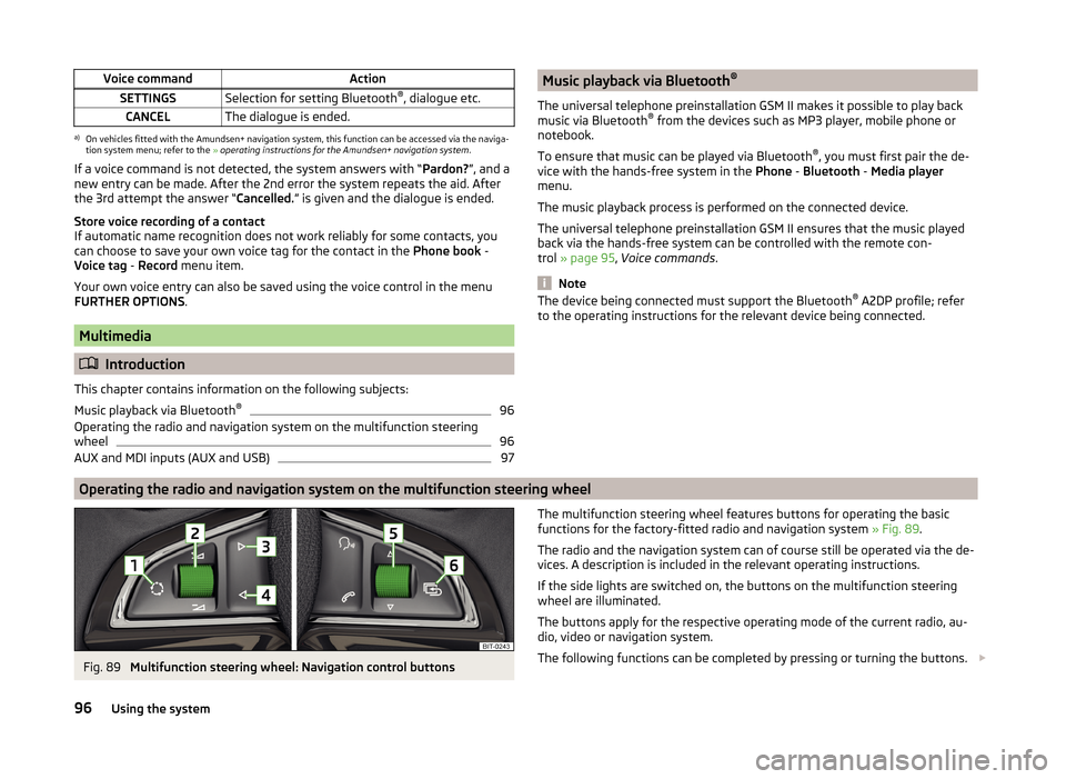
Fig. 89
Multifunction steering wheel: Navigation control buttons
The multifunction steering wheel features buttons for operating the basic
functions for the factory-fitted radio and navigation system » Fig. 89.
The radio and the navigation system can of course still be operated via the de-
vices. A description is included in the relevant operating instructions.
If the side lights are switched on, the buttons on the multifunction steering wheel are illuminated.
The buttons apply for the respective operating mode of the current radio, au-
dio, video or navigation system.
The following functions can be completed by pressing or turning the buttons. 96Using the system
Page 108 of 200
CAUTION■If the selector lever is moved to mode N while driving, the accelerator pedal
must be released and you will need to wait until the engine has reached its
idling speed before moving the selector lever to a forward driving mode again.■
When the outdoor temperature is below -10 ° C, the selector lever when
starting must always be in P mode.
■
When stopping on a slope, never try to hold the vehicle using the accelerator
pedal – this may lead to gear damage.
Note
After the ignition is switched off, the ignition key can only be withdrawn if the
selector lever is in the position P.
Modes and use of selector lever
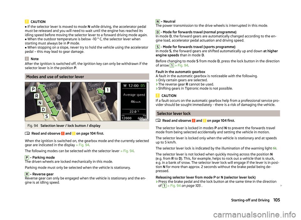
Fig. 94
Selection lever / lock button / display
Read and observe
and on page 104 first.
When the ignition is switched on, the gearbox mode and the currently selected gear are indicated in the display » Fig. 94.
The following modes can be selected with the selector lever » Fig. 94.
P
– Parking mode
The driven wheels are locked mechanically in this mode.
Parking mode must only be selected when the vehicle is stationary.
R
– Reverse gear
Reverse gear can only be engaged when the vehicle is stationary and the en-
gine is at idling speed.
N – Neutral
The power transmission to the drive wheels is interrupted in this mode.D
- Mode for forwards travel (normal programme)
In mode D, the forward gears are automatically changed according to the en-
gine load, accelerator pedal actuation and driving speed.
S
- Mode for forwards travel (sports programme)
In mode S, the forward gears are shifted automatically up and down at higher
engine speeds than in mode D.
Before changing to mode S from mode D, press the lock button in the direction
of arrow
1
» Fig. 94 .
Fault in the automatic gearbox
A fault in the automatic gearbox is noticeable with the following.
› Only certain gears are selected.
› The reverse gear
R cannot be used.
› Shifting gears in Tiptronic mode is not possible.
CAUTION
If a fault occurs on the automatic gearbox help from a professional service pro-
vider should be sought immediately - there is a risk of damaging the vehicle.
Selector lever lock
Read and observe
and on page 104 first.
The selector lever is locked in modes P and N to prevent the forwards travel
mode from being selected accidentally and setting the vehicle in motion.
The selector lever is locked only when the vehicle is stationary and at speeds
up to 5 km/h.
The selector lever lock is indicated by the illumination of the warning light .
The selector lever is not locked when quickly moving across the position N
(e.g. from R to D). This, for example, helps to rock out a vehicle that is stuck,
e.g. in a bank of snow. The selector lever lock will engage if the lever is in posi-
tion N for more than approx. 2 seconds without the brake pedal being de-
pressed.
Releasing selector lever from mode P or N (selector lever lock)
›
Press the brake pedal and the lock button at the same time in the direction
of
1
» Fig. 94 on page 105 .
105Starting-off and Driving
Page 116 of 200

Operating conditions of the systemFig. 100
MAXI DOT display: Engine is au-
tomatically switched off / auto-
matic engine cut off is not possi-
ble
Read and observe on page 112 first.
For system-dependent automatic engine shutdown
to work, the following conditions must be met.
The driver's door is closed.
The driver has fastened the seat belt.
The bonnet is closed.
The driving speed was higher than 4 km/h after the last stop.
No trailer is coupled.
Some additional conditions for the system to function correctly cannot be in-
fluenced or recognised by the driver. Therefore, the system can react differ-
ently in situations which are identical from the driver's perspective.
If after stopping the car, the message START-STOP NOT POSSIBLE appears in
the segment display or the MAXI DOT display shows the
» Fig. 100 warning
sign, then the conditions for automatic engine shutdown are not being met.
Running the engine is essential for the following reasons, for example.
› The engine temperature for the proper function of the system has not yet
been reached.
› The charge state of the vehicle battery is too low.
› The current consumption is too high.
› High air-conditioning or heating capacity (high fan speed, big difference be-
tween the desired and actual interior temperature).
Note■ If the vehicle remains outdoors for a long time in minus temperatures or in
direct sunlight, it can take several hours until the internal temperature of the
vehicle battery reaches a suitable temperature for proper operation of the
START STOP system.■
If the driver's seat belt is removed for more than approx. 30 seconds or the
driver's door is opened during stop mode, the engine will have to be started
manually.
■
After the manual engine start and with a manual gearbox the automatic en-
gine shutdown can take place only when a minimum distance required for the
system function has been covered.
Operation in vehicles with manual gearbox
Read and observe
on page 112 first.
In compliance with the operating conditions, automatic engine shutdown / au-
tomatic engine start takes place as described.
Automatic engine shutdown
›
Stop the vehicle.
›
Put the gear stick into Neutral.
›
Release the clutch pedal.
Automatic engine shutdown takes place, segment display shows START-STOP
ACTIVE or the MAXI DOT display shows the warning sign
» Fig. 100 on
page 113 .
Automatic engine start
›
Depress the clutch pedal.
The automatic start procedure takes place again.
Operation in vehicles with automatic gearbox
Read and observe
on page 112 first.
In compliance with the operating conditions, automatic engine shutdown / au-
tomatic engine start takes place as described.
Automatic engine shutdown
›
Bring the vehicle to a stop and depress the brake pedal.
113Assist systems
Page 128 of 200
The ŠKODA Service Partners are up-to-date on the legally required tests and
will prepare the vehicle for the tests as part of a service operation if required,
or will be responsible for carrying out these tests. The specialist garages can
carry out the specified tests directly if required by the customer if they are au-
thorised to do so. This saves you time and money.
Even if you want to take your vehicle to an officially approved test centre for
prior checking in preparation of a legally required test, we recommend that you
consult the service consultant of your ŠKODA Service Partner beforehand.
Based on their appraisal, the service consultant will tell you which areas you
should focus on in order to ensure that your vehicle will pass the technical test
without any problems. This allows you to avoid additional expenses resulting
from a possible subsequent test.
ŠKODA Service Partners
Read and observe
on page 124 first.
ŠKODA Service Partners feature modern, specially developed tools and equip-
ment. Here, trained specialists have access to a comprehensive range of
ŠKODA Original Parts and ŠKODA Original Accessories for carrying out modifi-
cations, repairs and technical alterations.
All ŠKODA service partners operate according to the most recent guidelines
and instructions from ŠKODA AUTO a.s. All service and repair work is therefore
carried out on time and at the appropriate quality. Adhering to these instruc-
tions and guidelines helps ensure road safety and helps keep your vehicle in a
good technical condition.
ŠKODA Service Partners are therefore properly prepared to service your vehicle
and to provide quality work. We therefore advise you to have all modifications,
repairs and technical alterations to your vehicle carried out by a ŠKODA Service
Partner.
ŠKODA Original parts
Read and observe
on page 124 first.
We recommend the use of ŠKODA Genuine Parts for your vehicle, as these
parts are approved by ŠKODA AUTO a.s.. They correspond precisely to the
ŠKODA AUTO a.s. regulations with regard to design, dimensional accuracy and
material, and are identical to the components used in series production.
ŠKODA AUTO a.s. is able to vouch for the safety, suitability and long service life
of these products. We therefore recommend that you only use ŠKODA Genuine
Parts.
ŠKODA AUTO a.s. supplies the market with a complete range of ŠKODA Genu-
ine Parts - not only while the model is still in production but for at least 15
years after the end of series production for wear parts and at least 10 years
after the end of series production for all other vehicle parts.
ŠKODA Service Partners are liable for any defects of ŠKODA Genuine Parts for a period of 2 years after sale in accordance with the materials defect liability,
unless agreed otherwise in the purchase agreement. You should keep the ap-
proved warranty certificate and the invoices for these components for this pe-
riod of time, so that the commencement of the term can be verified.
Body repairs
ŠKODA vehicles are designed such that if any damage occurs to the body, it is
only necessary to replace those parts that are actually damaged.
However, before you decide to have damaged body parts replaced, you should
first of all contact your specialist garage to determine whether or not the parts
can also be repaired. Repairs to body parts are usually cheaper.
ŠKODA Original accessories
Read and observe
on page 124 first.
If you wish to fit accessories to your vehicle, you should remember the follow-
ing:
We recommend that you use ŠKODA Genuine Accessories in your vehicle.
ŠKODA AUTO a.s. has selected these accessories to ensure that they are relia-
ble, safe and suitable for your particular vehicle. Although we constantly moni-
tor the market, we are not able to assess or vouch for other products even
though in some instances such parts may have operational approval or may
have been approved by a nationally recognised testing laboratory.
All accessory products are subjected to a challenging process in the areas of technical development (technical testing) and quality inspection (customer
testing), and the product only becomes a ŠKODA Genuine Accessory if all tests
are passed.
Our ŠKODA Genuine Accessories service also includes expert advice and pro-
fessional fitting if required by the customer.
125Care and maintenance
Page 154 of 200

CAUTIONThe tyres must be protected from contact with substances such as oil, grease
and fuel, which could damage them. If the tyres come into contact with these
substances, then we recommend you have this checked out in a specialist
workshop.
Unidirectional tyres
Read and observe
on page 148 first.
The direction of rotation of the tyres is marked by arrows on the wall of the
tyre .
The indicated direction of rotation must be adhered to in order to ensure the
optimal characteristics of these tyres.
These characteristics mainly relate to the following: › Increased driving stability.
› Reduced risk of aquaplaning.
› Reduced tyre noise and tyre wear.
Manufacturer-approved tyre variants
Introduction
This chapter contains information on the following subjects:
Explanation of the tyre labelling
151
Rapid
152
Rapid Green Line
152
Rapid Green tec
152
Approved tyre variants are first to be selected for the model variant (e.g. Rapid
GreenLine), and then selected according to the engine size of your vehicle.
If the model variant of your vehicle cannot be found in the discrete module,
then the approved tyre variants are to be selected according to the engine size
of your vehicle in module » page 152, Rapid .
Only use radial tyres of the same type, size (rolling circumference) and tread pattern on one axle on all four wheels.
When mounting new tyres the tyres have to be replaced axle by axle.
The information listed in the table corresponds to the information available at the time of going to press.
The approved tyre / rim combinations for your car are given on the sales and
technical vehicle documentation.
Explanation of the tyre labelling
Explanation of tyre markings
For example, 225/50R 17 91 T means:
225Tyre width in mm50Height/width ratio in %RCode letter for the type of tyre – Radial17Diameter of wheel in inches91Load indexTSpeed symbol
The date of manufacture is stated on the tyre wall (possibly on the inside).
For example DOT ... 11 14... means, for example, that the tyre was manufac-
tured in the 11th week of 2014.
The marking M+Smeans that the associated tyre is suitable for winter use.
Load index
The load index indicates the maximum permissible load for each individual
tyre.
Load index838485868788Load
(In kg)487500515530545560
Speed symbol
The maximum speed symbol indicates the maximum permissible vehicle speed
with fitted tyres in each category.
Speed
symbolSTUHVWMaximum speed
(in km/h)180190200210240270
151Wheels
Page 161 of 200
Installing›Push the cap onto the wheel bolt up to the stop.
Changing a wheel
When changing a wheel, the following instructions must be followed.
›
Remove the full wheel trim or the caps of the wheel bolts.
›
First of all slacken the anti-theft wheel bolt and then the other wheel bolts.
›
Jack up the vehicle until the wheel that needs changing is clear of the
ground.
›
Unscrew the wheel bolts and place them on a clean surface (cloth, paper, etc.).
›
Remove the wheel carefully.
›
Attach the spare wheel and slightly screw on the wheel bolts.
›
Lower the vehicle.
›
Alternately tighten wheel bolts opposite (diagonally) with the wheel wrench.
Tighten the anti-theft wheel bolt last.
›
Replace the wheel trim or the caps.
When fitting unidirectional tyres, ensure that the direction of rotation is cor-
rect » page 151 .
WARNING■
Undo the wheel bolts only a little (about one turn) provided that the vehi-
cle has not yet been jacked up. Otherwise the wheel could become loose
and fall off.■
All bolts must be clean and must turn easily.
■
If it is established when changing a wheel that the wheel bolts are corro-
ded and difficult to move, then these must be replaced.
■
Under no circumstances grease or oil the wheel bolts!
Follow-up work
After changing the wheel, the following work must be carried out.
›
Stow and attach the replaced wheel in the spare wheel well using a special
screw » page 155 .
›
Stow the tool kit in the space provided and secure using the band.
›
Check the tyre pressure on the installed spare wheel as soon as possible.
›Have the
tightening torque of the wheel bolts checked with a torque
wrench as soon as possible.
After changing the wheel, the tyre pressure should be adjusted. In vehicles
with tyre pressure monitoring, tyre pressure values are to be stored » page 115.
Replace the damaged wheel or consult a specialist garage about repair op-
tions.WARNINGInformation on the wheel bolts■The prescribed tightening torque of the wheel bolts for steel and light al-
loy wheels is 120 Nm.■
If the wheel bolts are tightened to a too low tightening torque, the rim
can come loose when the car is moving. A tightening torque which is too
high can damage the bolts and threads and this can result in permanent
deformation of the contact surfaces on the rim.
■
In case of incorrect treatment of the wheel bolts, the wheel can loosen
when the car is moving.
■
Drive cautiously and only at a moderate speed until the tightening torque
has been checked.
Loosening/tightening wheel bolts
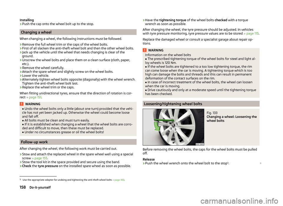
Fig. 133
Changing a wheel: Loosening the
wheel bolts
Before removing the wheel bolts, the caps for the wheel bolts must be pulled
off.
Release
›
Push the wheel wrench onto the wheel bolt to the stop 1)
.
1)
Use the appropriate adapter for undoing and tightening the anti-theft wheel bolts
» page 160.
158Do-it-yourself