brake sensor SKODA RAPID 2014 1.G Owner's Manual
[x] Cancel search | Manufacturer: SKODA, Model Year: 2014, Model line: RAPID, Model: SKODA RAPID 2014 1.GPages: 200, PDF Size: 25.57 MB
Page 37 of 200

Some error messages and other information are displayed in the MAXI DOT
display. The messages are displayed simultaneously with the icons in the MAXI
DOT display or with the warning lights in the instrument cluster » page 34,
Indicator lights .
The menu item Vehicle status is shown in the main menu of the MAXI DOT
display whenever at least one fault message exists. After selecting this menu,
the first of the error messages is displayed.
If there are several error messages, the display will show 1/3, for example, be-
low the message. This indicates that the first of a total of three error messag-
es is being displayed.
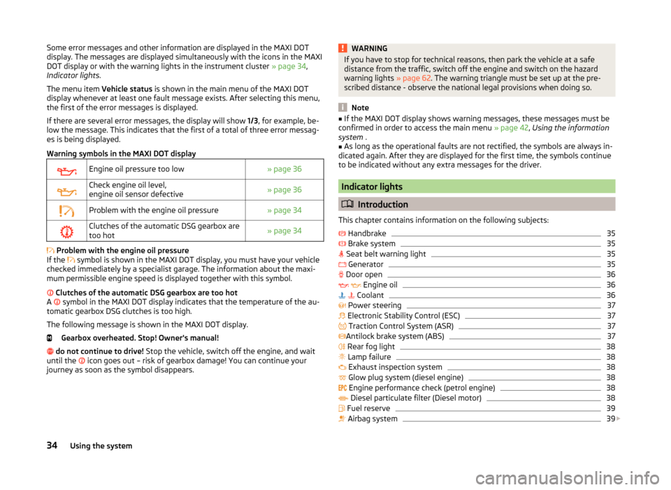
Warning symbols in the MAXI DOT displayEngine oil pressure too low» page 36Check engine oil level,
engine oil sensor defective» page 36Problem with the engine oil pressure» page 34Clutches of the automatic DSG gearbox are
too hot» page 34
Problem with the engine oil pressure
If the symbol is shown in the MAXI DOT display, you must have your vehicle
checked immediately by a specialist garage. The information about the maxi-
mum permissible engine speed is displayed together with this symbol.
Clutches of the automatic DSG gearbox are too hot
A symbol in the MAXI DOT display indicates that the temperature of the au-
tomatic gearbox DSG clutches is too high.
The following message is shown in the MAXI DOT display. Gearbox overheated. Stop! Owner's manual!
do not continue to drive! Stop the vehicle, switch off the engine, and wait
until the icon goes out – risk of gearbox damage! You can continue your
journey as soon as the symbol disappears.
WARNINGIf you have to stop for technical reasons, then park the vehicle at a safe
distance from the traffic, switch off the engine and switch on the hazard
warning lights » page 62. The warning triangle must be set up at the pre-
scribed distance - observe the national legal provisions when doing so.
Note
■ If the MAXI DOT display shows warning messages, these messages must be
confirmed in order to access the main menu » page 42, Using the information
system .■
As long as the operational faults are not rectified, the symbols are always in-
dicated again. After they are displayed for the first time, the symbols continue
to be indicated without any extra messages for the driver.
Indicator lights
Introduction
This chapter contains information on the following subjects:
Handbrake
35
Brake system
35
Seat belt warning light
35
Generator
35
Door open
36
Engine oil
36
Coolant
36
Power steering
37
Electronic Stability Control (ESC)
37
Traction Control System (ASR)
37
Antilock brake system (ABS)
37
Rear fog light
38
Lamp failure
38
Exhaust inspection system
38
Glow plug system (diesel engine)
38
Engine performance check (petrol engine)
38
Diesel particulate filter (Diesel motor)
38
Fuel reserve
39
Airbag system
39
34Using the system
Page 113 of 200

NoteFor vehicles without stabilization control (ESC), during a TCS intervention the
control indicator in the instrument cluster flashes.
Electronic Differential Lock (EDL)
Read and observe
on page 109 first.
EDL prevents the turning of the respective wheel of the driven axle. EDL
brakes the spinning wheel, if necessary, and transmits the driving force to the
other driving wheel. Driving becomes easier on road surfaces with different
traction under each wheel of the driven axle.
The EDL switches off automatically in order to avoid excessive heat generation
on the brake of the wheel being braked. The vehicle can continue to be driven
and has the same characteristics as a vehicle not fitted with EDL. Once the
brakes have cooled down, there is an automatic re-activation of EDL.
Hydraulic Brake Assist (HBA)
Read and observe
on page 109 first.
The HBA increases the braking effect and helps to reduce the braking dis-
tance.
The HBA is activated by the very quick operation of the brake pedal. In order to
achieve the shortest possible braking distance, the brake pedal must be ap-
plied firmly until the vehicle has come to a standstill.
The HBA function is automatically deactivated when the brake pedal is re-
leased.
Hill Hold Control (HHC)
Read and observe
on page 109 first.
When driving on slopes, HHC allows you to move your foot from the brake ped-al to the accelerator pedal without having to use the handbrake.
The system holds the brake pressure produced by the activation of the brake pedal for approx. 2 seconds after the brake pedal is released.
The brake pressure drops gradually the more you operate the accelerator ped-
al. If the vehicle does not start off within 2 seconds, it starts to roll back.
The HHC is active from a 5% slope if the driver's door is closed. HHC is only ev-
er active on slopes when in forward or reverse start off.
Parking aid
Introduction
This chapter contains information on the following subjects:
Function
111
Activation/deactivation
111
The parking aid (hereinafter referred to only as a system) draws attention via
acoustic signals and an indication in the radio or navigation display when ma-
noeuvring around obstacles in the vicinity of the vehicle.
The system uses ultrasound waves to calculate the distance between the
bumper and an obstacle. The ultrasonic sensors are integrated in the rear
bumper » Fig. 98 on page 111 .
WARNING■
The system only serves to support and does not relieve the driver of the
responsibility for the vehicle operation.■
Moving persons or objects may not be recognized by the system sensors.
■
Under certain circumstances, surfaces of certain objects and types of
clothing cannot reflect the system signals. For this reason, such people or
objects may not be recognised by the system sensors.
■
External noise sources may affect the signals of the system sensors. Un-
der adverse conditions, this may cause objects or people not to be recog-
nised by the system.
■
Before reversing, you should make sure that there are no small obstacles,
such as rocks, thin posts, trailer drawbars etc. behind your vehicle. Such ob-
stacles may not be recognised by the system sensors.
CAUTION
■ Keep the system sensors clean, snow-and ice-free and do not cover with any
objects of any kind, otherwise the system functioning may be impaired.■
Under adverse weather conditions (heavy rain, water vapour, very low or
high temperatures etc.), the system function may be limited - “incorrect recog-
nition of obstacle”.
■
Additionally installed accessories such as e.g. bicycle carriers can impair the
system function.
110Driving
Page 173 of 200

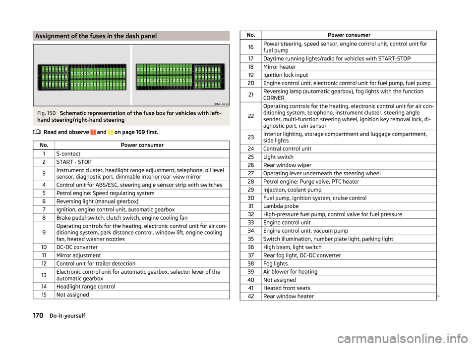
Assignment of the fuses in the dash panelFig. 150
Schematic representation of the fuse box for vehicles with left-
hand steering/right-hand steering
Read and observe
and on page 169 first.
No.Power consumer1S-contact2START - STOP3Instrument cluster, headlight range adjustment, telephone, oil level
sensor, diagnostic port, dimmable interior rear-view mirror4Control unit for ABS/ESC, steering angle sensor strip with switches5Petrol engine: Speed regulating system6Reversing light (manual gearbox)7Ignition, engine control unit, automatic gearbox8Brake pedal switch, clutch switch, engine cooling fan9Operating controls for the heating, electronic control unit for air con-
ditioning system, park distance control, window lift, engine cooling
fan, heated washer nozzles10DC-DC converter11Mirror adjustment12Control unit for trailer detection13Electronic control unit for automatic gearbox, selector lever of the
automatic gearbox14Headlight range control15Not assignedNo.Power consumer16Power steering, speed sensor, engine control unit, control unit for
fuel pump17Daytime running lights/radio for vehicles with START-STOP18Mirror heater19Ignition lock input20Engine control unit, electronic control unit for fuel pump, fuel pump21Reversing lamp (automatic gearbox), fog lights with the function
CORNER
22
Operating controls for the heating, electronic control unit for air con-
ditioning system, telephone, instrument cluster, steering angle
sender, multi-function steering wheel, ignition key removal lock, di-
agnostic port, rain sensor23Interior lighting, storage compartment and luggage compartment,
side lights24Central control unit25Light switch26Rear window wiper27Operating lever underneath the steering wheel28Petrol engine: Purge valve, PTC heater29Injection, coolant pump30Fuel pump, ignition system, cruise control31Lambda probe32High-pressure fuel pump, control valve for fuel pressure33Engine control unit34Engine control unit, vacuum pump35Switch illumination, number plate light, parking light36High beam, light switch37Rear fog light, DC-DC converter38Fog lights39Air blower for heating40Not assigned41Heated front seats42Rear window heater 170Do-it-yourself