fuses SKODA RAPID 2014 1.G Owner's Manual
[x] Cancel search | Manufacturer: SKODA, Model Year: 2014, Model line: RAPID, Model: SKODA RAPID 2014 1.GPages: 200, PDF Size: 25.57 MB
Page 6 of 200
Do-it-yourself
Emergency equipment and self-help154
Emergency equipment
154
Reserve and temporary spare wheel
155
Changing a wheel
156
Puncture set
160
Jump-starting
162
Towing the vehicle
164
Remote control
166
Emergency unlocking/locking
166
Replacing windscreen wiper blades
167
Fuses and light bulbs
169
Fuses
169
Replacing bulbs
172
Technical data
Technical data
177
Vehicle data
177
Index
3Table of Contents
Page 39 of 200
CAUTIONIf in addition to the warning light the warning light » page 36 lights up
while driving, stop driving - there is a risk of engine damage! Switch off the
engine and seek assistance from a specialist garage.
Door open
Read and observe
on page 35 first.
The indicator light
illuminates if one or several doors or luggage compart-
ment lid are opened.
Engine oil
Read and observe
on page 35 first.
The warning light flashes (low oil pressure)
The following message is shown in the MAXI DOT display.
Oil pressure: Engine off! Owner's manual!
› Stop the vehicle, switch off the engine, and check the engine oil lev-
el » page 141 .
› If the oil pressure is too low, top up the engine oil
» page 142.
If the oil level is within the specified range and the warning light flashes
again after the engine is started,
do not continue driving!
Switch off the engine and seek assistance from a specialist garage.
The indicator light lights up (oil quantity too low)
The following message is shown in the MAXI DOT display.
Check oil level!
› Stop the vehicle, switch off the engine, and check the engine oil lev-
el » page 141 .
The warning light will go out if the bonnet is left open for more than 30 sec-
onds . If no engine oil has been replenished, the warning light will
come on
again after driving about 100 km.
The indicator light flashes (engine oil level sensor faulty)
The following message is shown in the MAXI DOT display.
Oil sensor: Workshop!
If the engine oil level sensor is faulty, the warning light flashes several
times and an audible signal sounds when the ignition is turned on.
Seek assistance from a specialist garage immediately.
CAUTION
Stop driving if for some reason it is not possible to top up the engine oil un-
der the current conditions. Switch off the engine and seek assistance from a
specialist garage.
Coolant
Read and observe
on page 35 first.
The indicator light remains
illuminated until the engine reaches operating
temperature 1)
. Avoid high speeds, full throttle and high engine loads.
If the warning light
lights up or flashes , either the coolant temperature is
too high or the coolant level is too low.
The following message is shown in the MAXI DOT display. Check coolant! Owner's manual!
›
Stop the vehicle, switch off the engine and check the coolant lev-
el » page 143 .
›
If the coolant level is too low, add coolant to the reservoir » page 143.
If the indicator light
does not illuminate after adding coolant and switching
on the ignition, you may continue your journey.
If the coolant is within the specified range and the warning light is still
lit
after switching on the ignition, then there may be a malfunction of the cooling
fan.
›
Switch off the ignition.
›
Check the fuse for the radiator fan, replace if necessary » page 171, Fuses in
the engine compartment .
If the coolant level and fan fuse are OK and the warning light
lights up again
after switching on the ignition, do not continue driving!
Seek help from a specialist garage.
1)
Applies to cars with the instrument cluster - Version 2.
36Using the system
Page 62 of 200
Switching on the parking light or parking lights1)
» page 63
Switch on low beam 1)
Pull switch Switch on the front fog lamp » page 61
Switching on the rear fog light » page 61
Headlight range control
Turning the dial B
» Fig. 39 from the position
to
gradually adjusts the
headlight range control and thereby shortens the light cone.
The positions of the width of illumination correspond approximately to the fol-
lowing car load.
Front seats occupied, boot empty
All seats occupied, boot empty
All seats occupied, boot loaded
Driver seat occupied, boot loaded
We recommend you adjust the headlight beam when the low beam is switched
on.
WARNINGAlways adjust the headlight beam to meet the following conditions.■The vehicle does not dazzle other road users, especially oncoming vehi-
cles.■
The beam range is sufficient for safe driving.
Note
■ An audible warning signal will sound if the light switch is in the or posi-
tion, the ignition key is removed and the driver's door is opened. The audible
warning signal is switched off after a few seconds or as a result of door con-
tact when the driver's door is closed. However, the side lights remain on to illu-
minate the parked vehicle if necessary.■
If leaving the vehicle without needing the parking lights on, always turn
the light switch to position
.
Daytime running lights(DAY LIGHT)
Read and observe
on page 58 first.
The daytime running lights (the only function) provides the lighting of the frontvehicle range.
The lights are switched on automatically if the following conditions are met.
The light switch is in the position
or
» Fig. 39 on page 58 .
The ignition is switched on.
The parking aid is activated.
Deactivating the function
›
Switch off the ignition.
›
Remove the fuse for the daytime running lights » page 169, Fuses in the
dash panel .
Activating the function
›
Switch off the ignition.
›
Use a fuse of appropriate amperage for the daytime running
lights » page 169 , Fuses in the dash panel .
Disable function on vehicles with the START-STOP system or with the
automatic driving light control
›
Switch off the ignition.
›
Slide the turn signal light lever ( » Fig. 40 on page 60 ) downwards and hold
it in this position.
›
Switch on the ignition – wait until the left-turn signal light flashes 4x.
›
Switch off the ignition – an audible signal sounds which confirms the deacti-
vation of the function.
›
Release the turn signal stalk.
Function on vehicles with the START-STOP system or with the automatic
driving light control
›
Switch off the ignition.
›
Slide the turn signal light lever ( » Fig. 40 on page 60 ) upwards and hold it in
this position.
›
Switch on the ignition – wait until the right-turn signal light flashes 4x.
›
Switch off the ignition – an audible signal sounds which confirms the activa-
tion of the function.
1)
On vehicles with the instrument cluster - Version 1
» page 30 the symbol also illuminates on the light
switch.
59Lights and visibility
Page 92 of 200
Switching automatic mode onSwitching the intensive windshield defroster on/off - when this function
is switched on, the warning light illuminates in the button
Switching the airflow to the windows on and off
Switching the airflow to the upper body on and off
Switching the airflow to the footwell on and off
Switch recirculation on/off » page 87
Switch the cooling system on/off
After the cooling system is switched off, only the ventilation function remains active, whereby the lowest temperature that can be reached is the outside
temperature.
Setting temperature
The set temperature value appears in the display (pos. 2
» Fig. 86 ).
To switch between degrees Celsius and degrees Fahrenheit, the keys
and are to be pressed and held simultaneously.
The information appears in the display in the desired temperature measuring
unit (pos.
3
» Fig. 86 ).
The interior temperature can be set between +18 °C and +29 ℃. The interior
temperature is regulated automatically within this range.
If you select the temperature below +18 ℃, “LO” appears in the display.
If you select a temperature higher than +29 ℃, “HI” appears in the display.
At both end positions, Climatronic runs at maximum cooling/heating output
and the temperature is automatically not regulated.
Controlling blower
The Climatronic system controls the blower stages automatically in line with the interior temperature. However, the blower level can be manually adjusted
to suit your particular needs.
If the blower speed is reduced to a minimum, Climatronic is switched off.
The blower speed set is indicated by displaying the corresponding number of
segments (Pos.
9
» Fig. 86 ) in the display.
Automatic mode
The automatic mode is used in order to maintain a constant temperature and to demist the windows in the interior of the car.
To switch on press the button
. The display shows
(pos.
4
» Fig. 86 ).
Automatic mode can be
switched off by pressing one of the buttons for the air
distribution or by increasing/decreasing the blower speed. The temperature is
nevertheless regulated.WARNING■ Do not switch off the Climatronic system for longer than necessary.■Switch on the Climatronic system as soon as the windows mist up.
Note
■Do not stick anything on or cover the interior temperature sensor11 » Fig. 86 ; it could have an unfavourable effect on the Climatronic system.■
During operation of the Climatronic, an increase in engine idle speed can oc-
cur under certain circumstances in order to ensure adequate heating comfort.
■
As soon as the windscreen mists up, press the symbol button
. Press the
button
once the windscreen has demisted.
Efficient handling of the cooling system
Read and observe
and on page 85 first.
The air conditioning system compressor uses power from the engine when incooling mode, which will affect the fuel consumption.
It recommended to open the windows or the doors of a vehicle for which the
interior has been strongly heated through the effect of direct sunlight in order
to allow the heated air to escape.
The cooling system should not be on if the windows are open.
For the sake of the environment
Pollutant emissions are also reduced when fuel is saved » page 107.
malfunctions
Read and observe
and on page 85 first.
If the cooling system does not operate at outside temperatures higher than +5°C, there is a problem in the system. The reasons for this may be.
› One of the fuses has blown. Check the fuse and replace if necessa-
ry » page 169 .
› The cooling system has switched off automatically for a short time because
the coolant temperature of the engine is too hot » page 32.
89Heating and air conditioning
Page 124 of 200
NoteWe recommend that you use accessories from ŠKODA Original Accessories.
Trailer
Introduction
This chapter contains information on the following subjects:
Attaching and detaching trailers
121
Loading a trailer
122
Towing a trailer
122
Anti-theft alarm system
122
If your vehicle has already been factory-fitted with a towing device or is fitted
with a towing device from ŠKODA Original Accessories, then it meets all of the
technical requirements and national legal regulations for towing a trailer.
Note
If there is an error in the trailer lighting, check the fuses in the fuse box in the
dash panel » page 169.
Attaching and detaching trailers
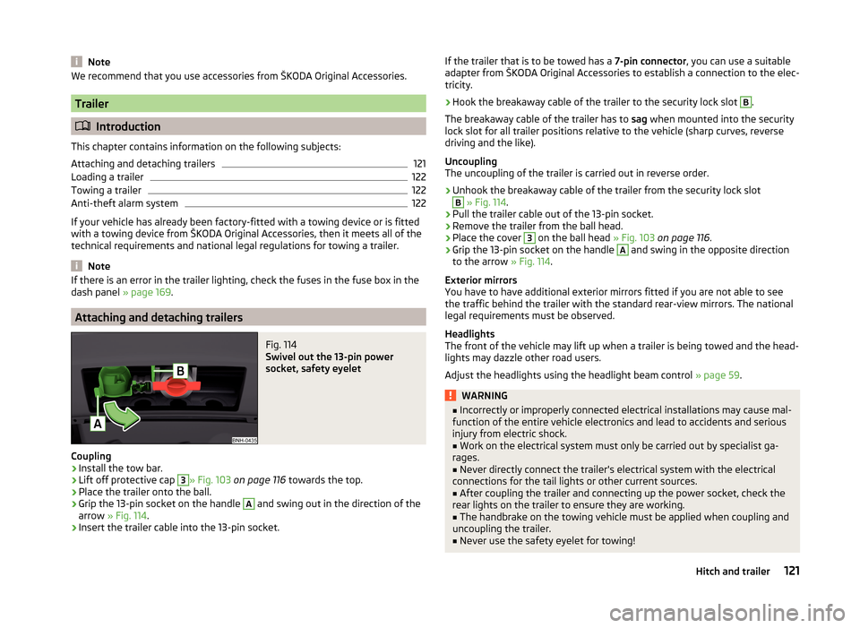
Fig. 114
Swivel out the 13-pin power
socket, safety eyelet
Coupling
›
Install the tow bar.
›
Lift off protective cap
3
» Fig. 103 on page 116 towards the top.
›
Place the trailer onto the ball.
›
Grip the 13-pin socket on the handle
A
and swing out in the direction of the
arrow » Fig. 114 .
›
Insert the trailer cable into the 13-pin socket.
If the trailer that is to be towed has a 7-pin connector, you can use a suitable
adapter from ŠKODA Original Accessories to establish a connection to the elec-
tricity.›
Hook the breakaway cable of the trailer to the security lock slot
B
.
The breakaway cable of the trailer has to sag when mounted into the security
lock slot for all trailer positions relative to the vehicle (sharp curves, reverse
driving and the like).
Uncoupling
The uncoupling of the trailer is carried out in reverse order.
›
Unhook the breakaway cable of the trailer from the security lock slot
B
» Fig. 114 .
›
Pull the trailer cable out of the 13-pin socket.
›
Remove the trailer from the ball head.
›
Place the cover
3
on the ball head » Fig. 103 on page 116 .
›
Grip the 13-pin socket on the handle
A
and swing in the opposite direction
to the arrow » Fig. 114.
Exterior mirrors
You have to have additional exterior mirrors fitted if you are not able to see
the traffic behind the trailer with the standard rear-view mirrors. The national
legal requirements must be observed.
Headlights
The front of the vehicle may lift up when a trailer is being towed and the head-
lights may dazzle other road users.
Adjust the headlights using the headlight beam control » page 59.
WARNING■
Incorrectly or improperly connected electrical installations may cause mal-
function of the entire vehicle electronics and lead to accidents and serious
injury from electric shock.■
Work on the electrical system must only be carried out by specialist ga-
rages.
■
Never directly connect the trailer's electrical system with the electrical
connections for the tail lights or other current sources.
■
After coupling the trailer and connecting up the power socket, check the
rear lights on the trailer to ensure they are working.
■
The handbrake on the towing vehicle must be applied when coupling and
uncoupling the trailer.
■
Never use the safety eyelet for towing!
121Hitch and trailer
Page 172 of 200
Fuses and light bulbs
Fuses
Introduction
This chapter contains information on the following subjects:
Fuses in the dash panel
169
Assignment of the fuses in the dash panel
170
Fuses in the engine compartment
171
Fuse assignment in the engine compartment
171
Individual electrical circuits are protected by fuses.
Switch off the ignition and the corresponding power consuming device before
replacing a fuse.
Find out which fuse belongs to the component that is not operat-
ing » page 170 , Assignment of the fuses in the dash panel or » page 171 ,
Fuse assignment in the engine compartment .
Fuse colourMaximum amperagelight brown5dark brown7.5red10blue15yellow20white25green30orange40WARNINGAlways read and observe the warning notes before completing any work in
the engine compartment » page 137, Engine compartment .CAUTION■
“Never repair” fuses, and do not replace them with fuses of a higher amper-
age – risk of fire! This may also cause damage at other points in the electrical
system.■
A blown fuses is recognisable by the molten metal strip. Replace the faulty
fuse with a new one of the same amperage.
■
If a newly inserted fuse burns through again, then a specialist should be con-
sulted immediately.
Note
■ We recommend always carrying replacement fuses in the vehicle. A box of
replacement fuses can be purchased from ŠKODA Original Accessories.■
There can be several power consuming devices for one fuse.
■
Multiple fuses may exist for a single power consuming device.
Fuses in the dash panel
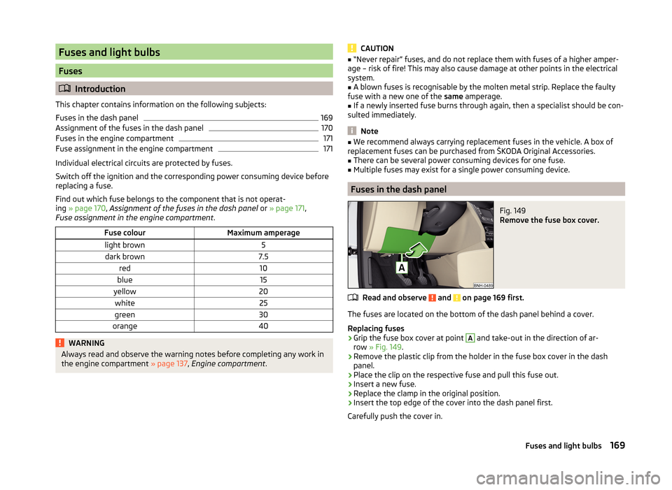
Fig. 149
Remove the fuse box cover.
Read and observe and on page 169 first.
The fuses are located on the bottom of the dash panel behind a cover.
Replacing fuses
›
Grip the fuse box cover at point
A
and take-out in the direction of ar-
row » Fig. 149 .
›
Remove the plastic clip from the holder in the fuse box cover in the dash
panel.
›
Place the clip on the respective fuse and pull this fuse out.
›
Insert a new fuse.
›
Replace the clamp in the original position.
›
Insert the top edge of the cover into the dash panel first.
Carefully push the cover in.
169Fuses and light bulbs
Page 173 of 200
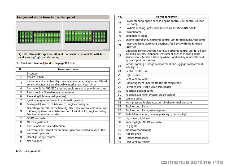
Assignment of the fuses in the dash panelFig. 150
Schematic representation of the fuse box for vehicles with left-
hand steering/right-hand steering
Read and observe
and on page 169 first.
No.Power consumer1S-contact2START - STOP3Instrument cluster, headlight range adjustment, telephone, oil level
sensor, diagnostic port, dimmable interior rear-view mirror4Control unit for ABS/ESC, steering angle sensor strip with switches5Petrol engine: Speed regulating system6Reversing light (manual gearbox)7Ignition, engine control unit, automatic gearbox8Brake pedal switch, clutch switch, engine cooling fan9Operating controls for the heating, electronic control unit for air con-
ditioning system, park distance control, window lift, engine cooling
fan, heated washer nozzles10DC-DC converter11Mirror adjustment12Control unit for trailer detection13Electronic control unit for automatic gearbox, selector lever of the
automatic gearbox14Headlight range control15Not assignedNo.Power consumer16Power steering, speed sensor, engine control unit, control unit for
fuel pump17Daytime running lights/radio for vehicles with START-STOP18Mirror heater19Ignition lock input20Engine control unit, electronic control unit for fuel pump, fuel pump21Reversing lamp (automatic gearbox), fog lights with the function
CORNER
22
Operating controls for the heating, electronic control unit for air con-
ditioning system, telephone, instrument cluster, steering angle
sender, multi-function steering wheel, ignition key removal lock, di-
agnostic port, rain sensor23Interior lighting, storage compartment and luggage compartment,
side lights24Central control unit25Light switch26Rear window wiper27Operating lever underneath the steering wheel28Petrol engine: Purge valve, PTC heater29Injection, coolant pump30Fuel pump, ignition system, cruise control31Lambda probe32High-pressure fuel pump, control valve for fuel pressure33Engine control unit34Engine control unit, vacuum pump35Switch illumination, number plate light, parking light36High beam, light switch37Rear fog light, DC-DC converter38Fog lights39Air blower for heating40Not assigned41Heated front seats42Rear window heater 170Do-it-yourself
Page 174 of 200
No.Power consumer43Horn44Windscreen wipers45Boot lid lock, central locking system46Alarm47Cigarette lighter48ABS49Turn signal lights, brake lights50DC-DC converter, radio51Electric windows (driver's window and rear left window)52Electric windows (front passenger's window and rear right)53Windscreen washer54START-STOP instrument cluster, operating lever under the steering
wheel, multifunction steering wheel55Control unit for automatic gearbox56Headlight cleaning system57Headlights front, rear58Headlights front, rear
Fuses in the engine compartment
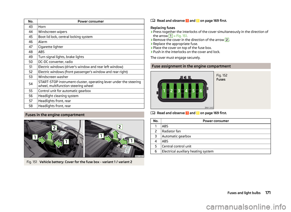
Fig. 151
Vehicle battery: Cover for the fuse box - variant 1 / variant 2
Read and observe and on page 169 first.
Replacing fuses
›
Press together the interlocks of the cover simultaneously in the direction of
the arrow
1
» Fig. 151 .
›
Remove the cover in the direction of the arrow
2
.
›
Replace the appropriate fuse.
›
Place the cover on top of the fuse box.
›
Push in the interlocks on the cover and lock.
The cover must engage securely.
Fuse assignment in the engine compartment
Fig. 152
Fuses
Read and observe and on page 169 first.
No.Power consumer1ABS2Radiator fan3Automatic gearbox4ABS5Central control unit6Electrical auxiliary heating system171Fuses and light bulbs
Page 176 of 200
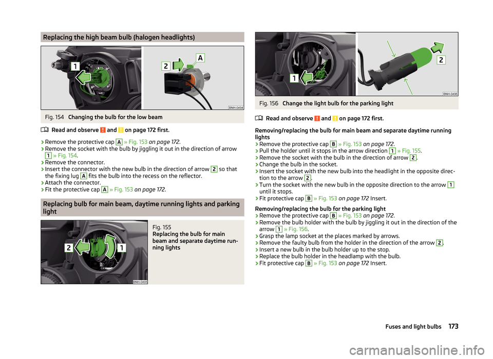
Replacing the high beam bulb (halogen headlights)Fig. 154
Changing the bulb for the low beam
Read and observe
and on page 172 first.
›
Remove the protective cap
A
» Fig. 153 on page 172 .
›
Remove the socket with the bulb by jiggling it out in the direction of arrow
1
» Fig. 154 .
›
Remove the connector.
›
Insert the connector with the new bulb in the direction of arrow
2
so that
the fixing lug
A
fits the bulb into the recess on the reflector.
›
Attach the connector.
›
Fit the protective cap
A
» Fig. 153 on page 172 .
Replacing bulb for main beam, daytime running lights and parking
light
Fig. 155
Replacing the bulb for main
beam and separate daytime run-
ning lights
Fig. 156
Change the light bulb for the parking light
Read and observe
and on page 172 first.
Removing/replacing the bulb for main beam and separate daytime running
lights
›
Remove the protective cap
B
» Fig. 153 on page 172 .
›
Pull the holder until it stops in the arrow direction
1
» Fig. 155 .
›
Remove the socket with the bulb in the direction of arrow
2
.
›
Change the bulb in the socket.
›
Insert the socket with the new bulb into the headlight in the opposite direc-
tion to the arrow
2
.
›
Turn the socket with the new bulb in the opposite direction to the arrow
1
until it stops.
›
Fit protective cap
B
» Fig. 153 on page 172 Insert.
Removing/replacing the bulb for the parking light
›
Remove the protective cap
B
» Fig. 153 on page 172 .
›
Remove the bulb holder with the bulb by jiggling it out in the direction of the
arrow
1
» Fig. 156 .
›
Grasp the lamp socket at the places marked by arrows.
›
Remove the faulty bulb from the holder in the direction of the arrow
2
.
›
Insert a new bulb in the bulb holder up to the stop.
›
Replace the bulb holder in the headlamp with the bulb.
›
Fit protective cap
B
» Fig. 153 on page 172 Insert.
173Fuses and light bulbs
Page 178 of 200

›Attach the connector.
Refit the headlight and grille›
Replace the fog light by inserting it in the opposite direction of the arrow
4
» Fig. 158 and tightening.
›
Insert the protective grille and carefully press it in.
The protective grille must engage firmly.
Replacing the bulb for the licence plate light
Fig. 159
Remove the number plate light/replace the bulb
Read and observe
and on page 172 first.
›
Open the boot lid.
›
Push in the lamp in the direction of the arrow
1
» Fig. 159 .
The lamp comes loose.
›
Swivel out the lamp in the direction of the arrow
2
and remove it.
›
Remove the faulty bulb from the holder in the direction of the arrow
3
.
›
Insert a new bulb into the holder.
›
Reinsert the lamp in the opposite direction to the arrow
1
.
›
Push on the light until the spring clicks into place.
Check that the light is securely inserted.
Rear LightFig. 160
Remove light / pull out connector
Read and observe
and on page 172 first.
Removing
›
Open the boot lid.
›
Insert the clamps for removing the full wheel covers » page 155, Vehicle tool
kit into opening
A
» Fig. 160 .
›
Remove the cover by pulling the hook in the direction of arrow
1
.
›
Unscrew the screws
B
with the key from the tool kit.
›
Grasp the lamp and carefully remove in the direction of arrow
2
.
›
Press the latch on the connector in the direction of arrow
3
.
›
Carefully remove the connector from the tail lamp assembly in the direction
of the arrow
4
.
Fitting
›
Insert the bulb holder into the lamp.
The lock on the plug must be inserted securely.
›
Insert the lamp with the pin
B
» Fig. 161 on page 176 into the recesses
C
» Fig. 160 in the body.
175Fuses and light bulbs