SKODA RAPID SPACEBACK 2013 1.G Owner's Guide
Manufacturer: SKODA, Model Year: 2013, Model line: RAPID SPACEBACK, Model: SKODA RAPID SPACEBACK 2013 1.GPages: 193, PDF Size: 14.8 MB
Page 21 of 193
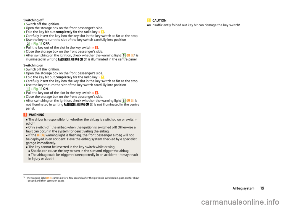
Switching off›Switch off the ignition.›
Open the storage box on the front passenger's side.
›
Fold the key bit out completely for the radio key » .
›
Carefully insert the key into the key slot in the key switch as far as the stop.
›
Use the key to turn the slot of the key switch carefully into position
2
» Fig. 12 OFF .
›
Pull the key out of the slot in the key switch » .
›
Close the storage box on the front passenger's side.
›
After switching on the ignition, check whether the warning light
3
1)
is
illuminated in writing
is illuminated in the centre panel.
Switching on
›
Switch off the ignition.
›
Open the storage box on the front passenger's side.
›
Fold the key bit out completely for the radio key » .
›
Carefully insert the key into the key slot in the key switch as far as the stop.
›
Use the key to turn the slot of the key switch carefully into position
1
» Fig. 12 ON .
›
Pull the key out of the slot in the key switch » .
›
Close the storage box on the front passenger's side.
›
After switching on the ignition, check whether the warning light
3
is
not illuminated in writing
is not illuminated in the centre
panel.
WARNING■ The driver is responsible for whether the airbag is switched on or switch-
ed off.■
Only switch off the airbag when the ignition is switched off! Otherwise a
fault can occur in the system for deactivating the airbag.
■
If the
warning light is flashing, the front passenger airbag will not
be deployed in an accident! Have the airbag system checked by a specialist
garage immediately.
■
The key cannot be inserted in the key switch while driving.
■ Shocks can cause the key to turn in the slot and trigger the airbag!
■ The airbag could be triggered unexpectedly in an accident - it may result
in injury or death!
CAUTIONAn insufficiently folded out key bit can damage the key switch!1)
The warning light comes on for a few seconds after the ignition is switched on, goes out for about
1 second and then comes on again.
19Airbag system
Page 22 of 193
Transporting children safely
Child seat
Introduction
This chapter contains information on the following subjects:
Use of a child seat on the front passenger seat
20
Child safety and side airbag
21
Classification of child seats
22
Use of child seats fastened with a seat belt
22
Children are generally safer on the rear seats than on the front passenger
seat.
In contrast to adults, the muscles and bone structure of children are not yet
fully developed. Thus children are exposed to increased risk of injury.
Children should be transported in accordance with the relevant statutory pro-
visions.
Child seats complying with the ECE-R 44 standard must be used. ECE-R stands
for: Economic Commission for Europe – Regulation.
The child seats according to the standard ECE-R 44are marked with a non-de-
tachable Certification: large E within a circle and below the test number.
WARNING■ The national legal requirements must be observed when using child
seats.■
One should never carry children, and also not babies! - on one's lap.
■
Never leave children unattended in the vehicle. Certain outside climatic
conditions can cause life-threatening temperatures in the vehicle.
■
The child must be secured in the vehicle during the entire journey! Other-
wise, the child would be thrown through the vehicle in the event of an acci-
dent, causing fatal injuries to both the child and other occupants.
■
Children are exposed to an increased risk of injury in the event of an acci-
dent if they lean forward or adopt an incorrect seated position when the
vehicle is moving. This particularly applies to children who are transported
on the front passenger seat as they can suffer severe, or even fatal injuries
if the airbag system is deployed!
WARNING (Continued)■ Pay particular attention to the information provided by the manufacturer
of the child safety seat regarding the correct routing of the belt. Seat belts
which are not correctly adjusted can themselves cause injuries even in mi-
nor accidents.■
Safety belts must be checked to ensure that they are running properly.
One should also ensure that the belt is not damaged by sharp-edged fit-
tings.
■
The front passenger airbag must be deactivated if using a rear-facing
child seat on the front passenger seat. Further information » page 20,
Use of a child seat on the front passenger seat .
CAUTION
When installing a child seat in which the child faces forward, adjust the head
restraints so that they are as high as possible.
Note
We recommend that you use child seats from ŠKODA Original Accessories.
These child seats were developed and also tested for use in ŠKODA vehicles.
They meet the ECE-R 44 standard.
Use of a child seat on the front passenger seat
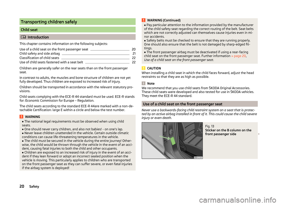
Never use a backwards-facing child restraint system on a seat that is protec-
ted by an active airbag installed in front of it. This could cause the child severe
injury or even death.
Fig. 13
Sticker on the B column on the
front passenger side
20Safety
Page 23 of 193
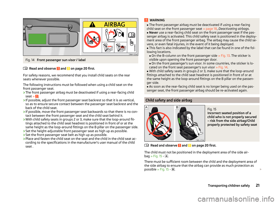
Fig. 14
Front passenger sun visor / label
Read and observe
and on page 20 first.
For safety reasons, we recommend that you install child seats on the rear
seats whenever possible.
The following instructions must be followed when using a child seat on the
front passenger seat.
› The front passenger airbag must be deactivated if using a rear-facing child
seat »
.
› If possible, adjust the front passenger seat backrest so that it is as vertical,
so as to ensure secure contact between the passenger seat backrest and the
back of the child seat.
› If possible, move the front passenger seat backwards so that there is no con-
tact between the front passenger seat and the child seat behind it.
› With child safety seats in groups 2 or 3, make sure that the loop-around fit-
tings attached to the child seat headrest is positioned in front of or at the
same height as the loop-around fittings on the B pillar on the passenger side.
› Set the height-adjustable front passenger seat as high up as possible.
› Set the front passenger seat belt as high up as possible.
› Place and fasten the child seat on the seat and the child in the child seat ac-
cording to the specifications in the manufacturer's user manual of the child
seat .
WARNING■ The front passenger airbag must be deactivated if using a rear-facing
child seat on the front passenger seat » page 18, Deactivating airbags .■
Never use a rear-facing child seat on the front passenger seat if the pas-
senger airbag is activated. This child safety seat is positioned in the deploy-
ment area of the front passenger airbag. The airbag may cause the child se-
vere, or even fatal injuries, in the event of it being deployed.
■
This fact is also indicated by the label that can be found in one of the fol-
lowing locations. ■On the B-column on the front passenger side » Fig. 13. The sticker is
visible upon opening the front passenger door.
■ On the front passenger's sun visor. In some countries, the sticker is lo-
cated on the front seat passenger's sun visor » Fig. 14.
■
With child safety seats in groups 2 or 3, make sure that the loop-around
fittings attached to the child seat headrest is positioned in front of or at
the same height as the loop-around fittings on the B pillar on the passen-
ger side.
■
As soon as the rear-facing child seat is no longer being used on the pas-
senger seat, the front passenger airbag should be re-activated again.
Child safety and side airbag
Fig. 15
Incorrect seated position of a
child who is not properly secured
– risk from the side airbag/Child
properly protected by safety seat
Read and observe and on page 20 first.
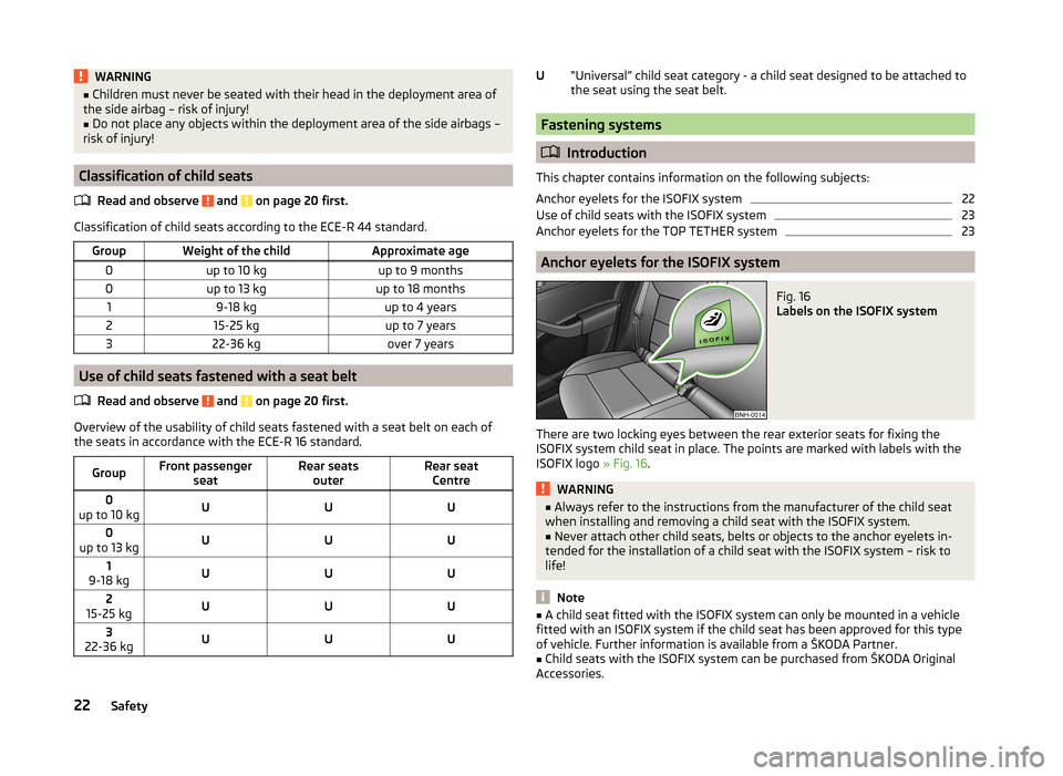
The child must not be positioned in the deployment area of the side air-
bag » Fig. 15 -
.
There must be sufficient room between the child and the deployment area of
the side airbag to ensure that the airbag can provide as much protection as
possible » Fig. 15 -
.
21Transporting children safely
Page 24 of 193
WARNING■Children must never be seated with their head in the deployment area of
the side airbag – risk of injury!■
Do not place any objects within the deployment area of the side airbags –
risk of injury!
Classification of child seats
Read and observe
and on page 20 first.
Classification of child seats according to the ECE-R 44 standard.
GroupWeight of the childApproximate age0up to 10 kgup to 9 months0up to 13 kgup to 18 months19-18 kgup to 4 years215-25 kgup to 7 years322-36 kgover 7 years
Use of child seats fastened with a seat belt Read and observe
and on page 20 first.
Overview of the usability of child seats fastened with a seat belt on each ofthe seats in accordance with the ECE-R 16 standard.
GroupFront passenger seatRear seatsouterRear seatCentre0
up to 10 kgUUU0
up to 13 kgUUU1
9-18 kgUUU2
15-25 kgUUU3
22-36 kgUUU“Universal” child seat category - a child seat designed to be attached to the seat using the seat belt.
Fastening systems
Introduction
This chapter contains information on the following subjects:
Anchor eyelets for the ISOFIX system
22
Use of child seats with the ISOFIX system
23
Anchor eyelets for the TOP TETHER system
23
Anchor eyelets for the ISOFIX system
Fig. 16
Labels on the ISOFIX system
There are two locking eyes between the rear exterior seats for fixing the
ISOFIX system child seat in place. The points are marked with labels with the
ISOFIX logo » Fig. 16.
WARNING■
Always refer to the instructions from the manufacturer of the child seat
when installing and removing a child seat with the ISOFIX system.■
Never attach other child seats, belts or objects to the anchor eyelets in-
tended for the installation of a child seat with the ISOFIX system – risk to
life!
Note
■ A child seat fitted with the ISOFIX system can only be mounted in a vehicle
fitted with an ISOFIX system if the child seat has been approved for this type
of vehicle. Further information is available from a ŠKODA Partner.■
Child seats with the ISOFIX system can be purchased from ŠKODA Original
Accessories.
U22Safety
Page 25 of 193
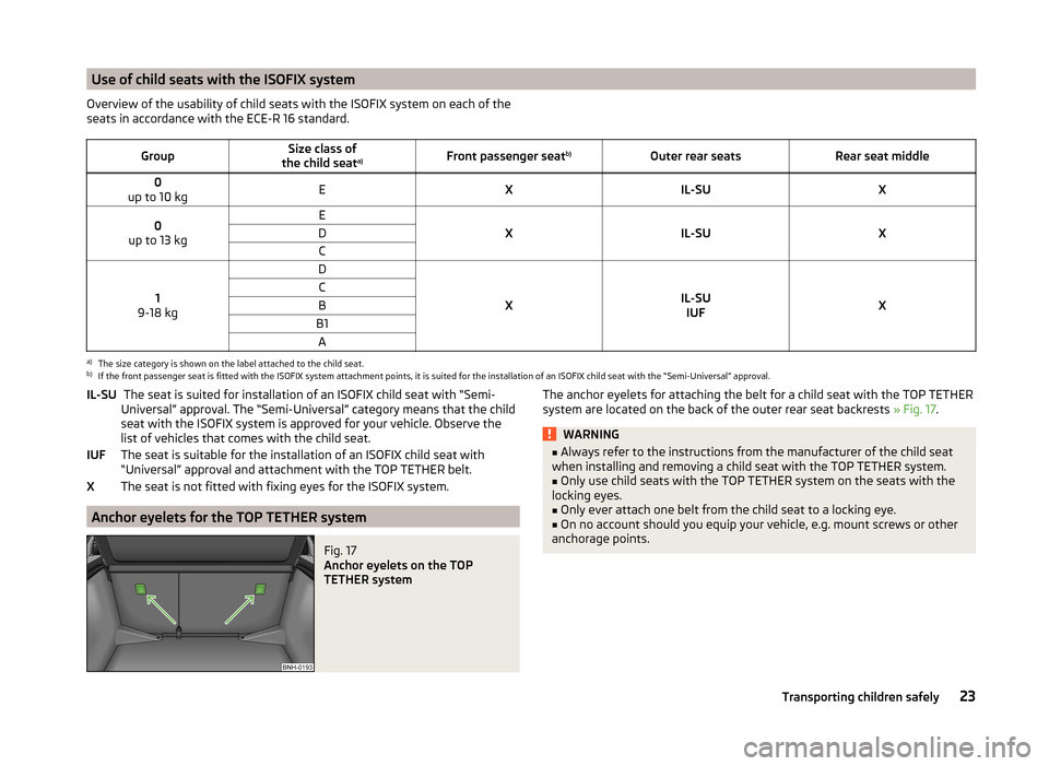
Use of child seats with the ISOFIX systemOverview of the usability of child seats with the ISOFIX system on each of the
seats in accordance with the ECE-R 16 standard.GroupSize class of
the child seat a)Front passenger seat
b)Outer rear seatsRear seat middle0
up to 10 kgEXIL-SUX0
up to 13 kgE
XIL-SUX
DC
1
9-18 kg
D
XIL-SU IUFX
CBB1Aa)
The size category is shown on the label attached to the child seat.
b)
If the front passenger seat is fitted with the ISOFIX system attachment points, it is suited for the installation of an ISOFIX child seat with the “Semi-Universal” approval.
The seat is suited for installation of an ISOFIX child seat with “Semi-
Universal” approval. The “Semi-Universal” category means that the child
seat with the ISOFIX system is approved for your vehicle. Observe the
list of vehicles that comes with the child seat.
The seat is suitable for the installation of an ISOFIX child seat with
“Universal” approval and attachment with the TOP TETHER belt.
The seat is not fitted with fixing eyes for the ISOFIX system.
Anchor eyelets for the TOP TETHER system
Fig. 17
Anchor eyelets on the TOP
TETHER system
IL-SUIUFXThe anchor eyelets for attaching the belt for a child seat with the TOP TETHER system are located on the back of the outer rear seat backrests » Fig. 17.WARNING■
Always refer to the instructions from the manufacturer of the child seat
when installing and removing a child seat with the TOP TETHER system.■
Only use child seats with the TOP TETHER system on the seats with the
locking eyes.
■
Only ever attach one belt from the child seat to a locking eye.
■
On no account should you equip your vehicle, e.g. mount screws or other
anchorage points.
23Transporting children safely
Page 26 of 193
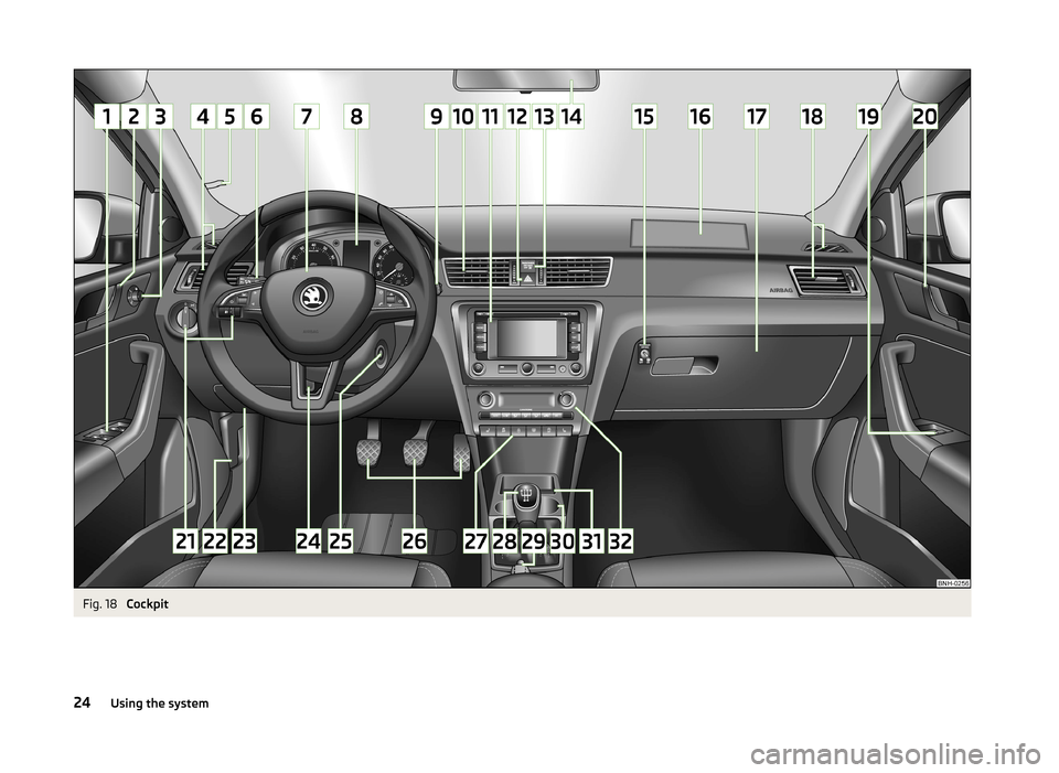
Fig. 18
Cockpit
24Using the system
Page 27 of 193
Using the system
Cockpit
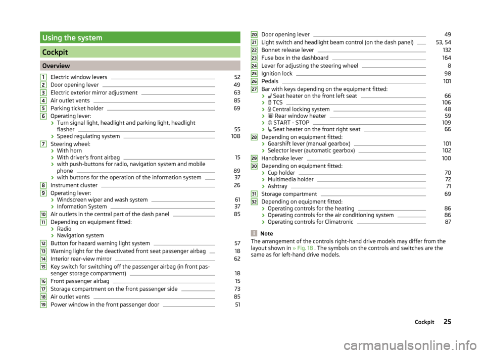
OverviewElectric window levers
52
Door opening lever
49
Electric exterior mirror adjustment
63
Air outlet vents
85
Parking ticket holder
69
Operating lever:
› Turn signal light, headlight and parking light, headlight
flasher
55
› Speed regulating system
108
Steering wheel:
› With horn
› With driver’s front airbag
15
›with push-buttons for radio, navigation system and mobile
phone
89
› with buttons for the operation of the information system
37
Instrument cluster
26
Operating lever:
› Windscreen wiper and wash system
61
›Information System
37
Air outlets in the central part of the dash panel
85
Depending on equipment fitted:
› Radio
› Navigation system
Button for hazard warning light system
57
Warning light for the deactivated front seat passenger airbag
18
Interior rear-view mirror
62
Key switch for switching off the passenger airbag (in front pas-
senger storage compartment)
18
Front passenger airbag
15
Storage compartment on the front passenger side
73
Air outlet vents
85
Power window in the front passenger door
5112345678910111213141516171819Door opening lever49
Light switch and headlight beam control (on the dash panel)
53, 54
Bonnet release lever
132
Fuse box in the dashboard
164
Lever for adjusting the steering wheel
8
Ignition lock
98
Pedals
101
Bar with keys depending on the equipment fitted:
›
Seat heater on the front left seat
66
›
TCS
106
›
Central locking system
48
›
Rear window heater
59
›
START - STOP
109
›
Seat heater on the front right seat
66
Depending on equipment fitted:
› Gearshift lever (manual gearbox)
101
›Selector lever (automatic gearbox)
102
Handbrake lever
100
Depending on equipment fitted:
› Cup holder
70
›Multimedia holder
72
›Ashtray
71
Storage compartment
69
Depending on equipment fitted:
› Operating controls for the heating
86
›Operating controls for the air conditioning system
86
›Operating controls for Climatronic
87
Note
The arrangement of the controls right-hand drive models may differ from the
layout shown in » Fig. 18 . The symbols on the controls and switches are the
same as for left-hand drive models.2021222324252627282930313225Cockpit
Page 28 of 193
Instruments and Indicator Lights
Instrument cluster
Introduction
This chapter contains information on the following subjects:
Overview
26
Revolution counter
27
Display
27
Speedometer
27
Coolant temperature gauge
27
Fuel gauge
28
Counter for distance driven
28
29
Display of the second speed
29
Auto Check Control
29
The instrument cluster gives the driver basic information such as the current
speed, engine speed, the state of some vehicle systems and the like.
Fault display
If there is a fault in the instrument cluster, the Error message will appear in
the display.
Seek help from a specialist garage.
WARNINGConcentrate fully at all times on your driving! As the driver you are fully re-
sponsible for road safety.
Note
When the ignition is on, the instrument cluster is illuminated 1)
. The brightness
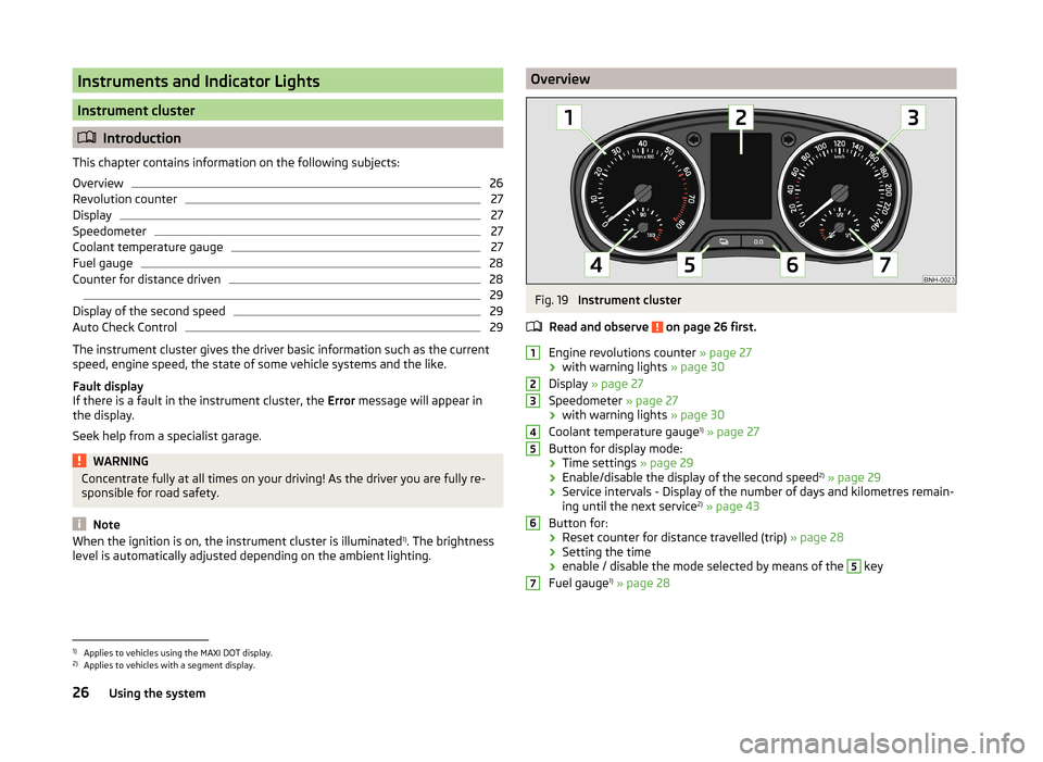
level is automatically adjusted depending on the ambient lighting.OverviewFig. 19
Instrument cluster
Read and observe
on page 26 first.
Engine revolutions counter » page 27
› with warning lights
» page 30
Display » page 27
Speedometer » page 27
› with warning lights
» page 30
Coolant temperature gauge 1)
» page 27
Button for display mode:
› Time settings
» page 29
› Enable/disable the display of the second speed 2)
» page 29
› Service intervals - Display of the number of days and kilometres remain-
ing until the next service 2)
» page 43
Button for: › Reset counter for distance travelled (trip)
» page 28
› Setting the time
› enable / disable the mode selected by means of the
5
key
Fuel gauge 1)
» page 28
12345671)
Applies to vehicles using the MAXI DOT display.
2)
Applies to vehicles with a segment display.
26Using the system
Page 29 of 193
Revolution counterRead and observe
on page 26 first.
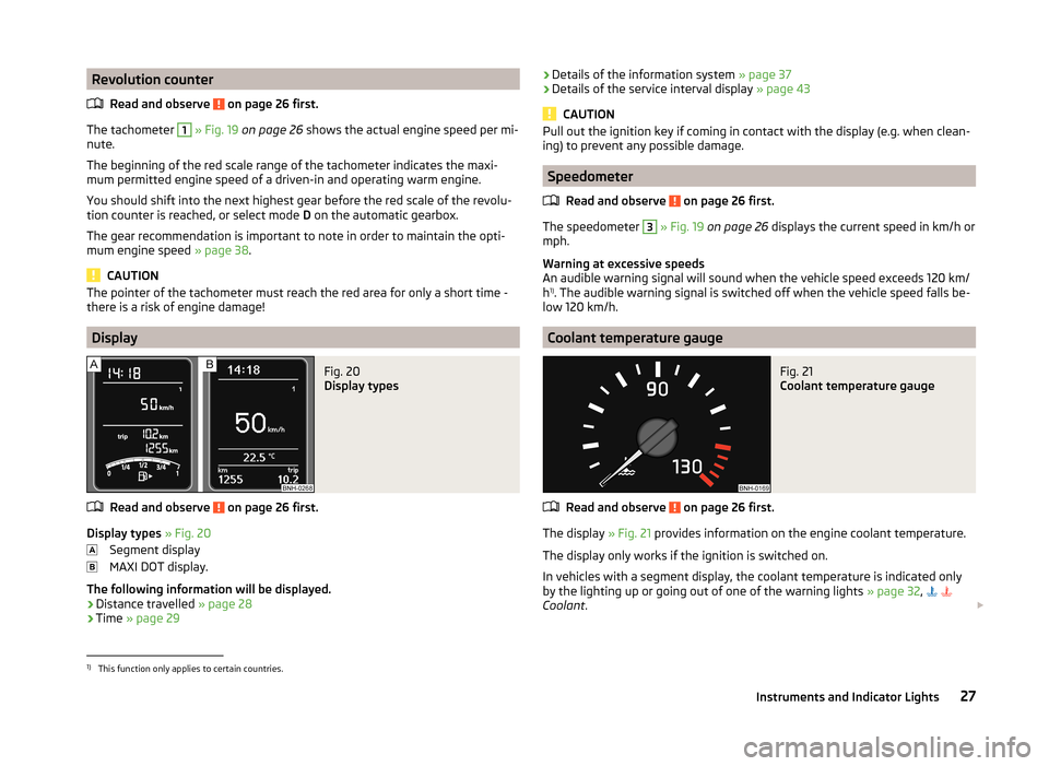
The tachometer
1
» Fig. 19 on page 26 shows the actual engine speed per mi-
nute.
The beginning of the red scale range of the tachometer indicates the maxi-
mum permitted engine speed of a driven-in and operating warm engine.
You should shift into the next highest gear before the red scale of the revolu- tion counter is reached, or select mode D on the automatic gearbox.
The gear recommendation is important to note in order to maintain the opti-
mum engine speed » page 38.
CAUTION
The pointer of the tachometer must reach the red area for only a short time -
there is a risk of engine damage!
Display
Fig. 20
Display types
Read and observe on page 26 first.
Display types » Fig. 20
Segment display
MAXI DOT display.
The following information will be displayed.
› Distance travelled
» page 28
› Time
» page 29
›Details of the information system
» page 37
› Details of the service interval display
» page 43
CAUTION
Pull out the ignition key if coming in contact with the display (e.g. when clean-
ing) to prevent any possible damage.
Speedometer
Read and observe
on page 26 first.
The speedometer
3
» Fig. 19 on page 26 displays the current speed in km/h or
mph.
Warning at excessive speeds
An audible warning signal will sound when the vehicle speed exceeds 120 km/
h 1)
. The audible warning signal is switched off when the vehicle speed falls be-
low 120 km/h.
Coolant temperature gauge
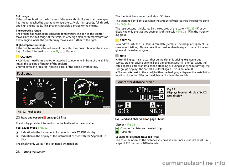
Fig. 21
Coolant temperature gauge
Read and observe on page 26 first.
The display » Fig. 21 provides information on the engine coolant temperature.
The display only works if the ignition is switched on.
In vehicles with a segment display, the coolant temperature is indicated only by the lighting up or going out of one of the warning lights » page 32,
Coolant .
1)
This function only applies to certain countries.
27Instruments and Indicator Lights
Page 30 of 193
Cold range
If the pointer is still in the left area of the scale, this indicates that the engine
has not yet reached its operating temperature. Avoid high speeds, full throttle
and high engine loads. This prevents possible damage to the engine.
The operating range
The engine has reached its operating temperature as soon as the pointer
moves into the mid-range of the scale. At very high ambient temperatures or
heavy engine loads, the pointer may move even further to the right.
High temperature range
If the pointer reaches the red area of the scale, the coolant temperature is too high. Further information » page 32,
Coolant .
CAUTION
■
Additional headlights and other attached components in front of the air inlet
impair the cooling efficiency of the coolant.■
Never cover the radiator - there is a risk of the engine overheating.
Fuel gauge
Fig. 22
Fuel gauge
Read and observe
on page 26 first.
The display provides information on the fuel level in the container.
Fuel gauge types » Fig. 22
Indication in the instrument cluster with the MAXI DOT display
Indication in the display of the instrument cluster with the Segment Dis-
play
The display only works if the ignition is switched on.
The fuel tank has a capacity of about 55 litres.
The warning light lights up when the amount of fuel reaches the reserve zone
» page 35 .
The reserve zone is indicated by the red area of the scale » Fig. 22 -
or by
displaying only the last two segments of the scale » Fig. 22 -
in the magnify-
ing glass.
CAUTION
Never drive until the fuel tank is completely empty! The irregular supply of fuel
can cause misfiring. This can result in considerable damage to parts of the en-
gine and the exhaust system.
Note
■ After filling up, it can occur that during dynamic driving (e.g. numerous
curves, braking, driving downhill and climbing a steep hill) the fuel gauge indi-
cates approx. a fraction less. When stopping or during less dynamic driving, the
fuel gauge displays the correct fuel level again. This is not a fault.■
The arrow
next to the icon
within the fuel gauge displays the installation
location of the fuel filler on the right-hand side of the vehicle.
Counter for distance driven
Fig. 23
Display: Segment display / MAXI
DOT display
Read and observe on page 26 first.
Display » Fig. 23
Counter for distance travelled (trip)
Odometer
Counter for distance travelled (trip)
The counter indicates the distance you have driven since it was last reset - in
steps of 100 metres or 1/10 of a mile.
AB28Using the system