check engine SKODA RAPID SPACEBACK 2013 1.G Owner's Guide
[x] Cancel search | Manufacturer: SKODA, Model Year: 2013, Model line: RAPID SPACEBACK, Model: SKODA RAPID SPACEBACK 2013 1.GPages: 193, PDF Size: 14.8 MB
Page 135 of 193
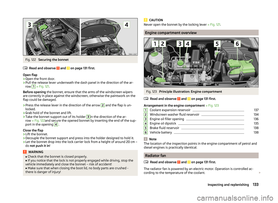
Fig. 122
Securing the bonnet
Read and observe
and on page 131 first.
Open flap
›
Open the front door.
›
Pull the release lever underneath the dash panel in the direction of the ar-
row
1
» Fig. 121 .
Before opening the bonnet, ensure that the arms of the windscreen wipers
are correctly in place against the windscreen, otherwise the paintwork on the
flap could be damaged.
›
Press the release lever in the direction of the arrow
2
and the flap is un-
locked.
›
Grab hold of the bonnet and lift.
›
Take the bonnet support out of its holder
3
in the direction of the ar-
row » Fig. 122 and secure the opened bonnet by inserting the end of the sup-
port in the opening
4
.
Close the flap
›
Lift the bonnet.
›
Decouple the bonnet support and press into the holder designed to hold it.
›
Let the bonnet drop into the lock carrier lock from a height of around 20 cm –
do not push it in !
WARNING■
Check that the bonnet is closed properly.■If you notice that the lock is not properly engaged while driving, stop the
vehicle immediately and close the bonnet – risk of accident!■
Make sure that when closing the boot lid, no body parts are crushed -
there is danger of injury!
CAUTIONNever open the bonnet by the locking lever » Fig. 121.
Engine compartment overview
Fig. 123
Principle illustration: Engine compartment
Read and observe
and on page 131 first.
Arrangement in the engine compartment » Fig. 123
Coolant expansion reservoir
137
Windscreen washer fluid reservoir
134
Engine oil filler opening
136
Engine oil dipstick
135
Brake fluid reservoir
138
Vehicle battery
138
Note
The location of the inspection points in the engine compartment of petrol and
diesel engines is practically identical.
Radiator fan
Read and observe
and on page 131 first.
The radiator fan is powered by an electric motor. Operation is controlled ac-
cording to the temperature of the coolant.
123456133Inspecting and replenishing
Page 136 of 193
WARNINGAfter switching off the ignition, the fan may intermittently continue to op-
erate for approx. 10 minutes.
Windscreen washer system
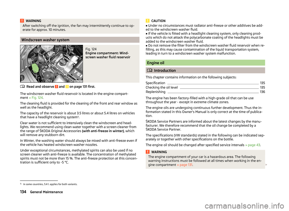
Fig. 124
Engine compartment: Wind-
screen washer fluid reservoir
Read and observe and on page 131 first.
The windscreen washer fluid reservoir is located in the engine compart-
ment » Fig. 124 .
The cleaning fluid is provided for the cleaning of the front and rear window as
well as the headlight.
The capacity of the reservoir is about 3.5 litres or about 5.4 litres on vehicles
that have a headlight cleaning system 1)
.
Clear water is not sufficient to intensively clean the windscreen and head-
lights. We recommend using clean water together with a screen cleaner from
the range of ŠKODA Original Accessories (with anti-freeze in winter), which
will remove any stubborn dirt.
In Winter, the washing water should always be mixed with anti-freeze even if
the vehicle has heated windscreen washer nozzles.
Under exceptional circumstances, methylated spirits can also be used if no
screen cleaner with anti-freeze is available. The concentration of methylated
spirits must not be more than 15 %. The anti-freeze protection at this concen-
tration is sufficient only to -5 °C.
CAUTION■ Under no circumstances must radiator anti-freeze or other additives be add-
ed to the windscreen washer fluid.■
If the vehicle is fitted with a headlight cleaning system, only cleaning prod-
ucts which do not attack the polycarbonate coating of the headlights must be
added to the windscreen washer fluid.
■
Do not remove the filter from the windscreen washer fluid reservoir when re-
filling, as this may cause contamination of the liquid transportation system,
leading in turn to a windscreen washer system malfunction.
Engine oil
Introduction
This chapter contains information on the following subjects:
Specification
135
Checking the oil level
135
Replenishing
136
The engine has been factory-filled with a high-grade oil that can be use
throughout the year - except in extreme climate zones.
The engine oils are undergoing continuous further development. Thus the in- formation stated in this Owner's Manual is only correct at the time of publica-
tion.
ŠKODA Service Partners are informed about the latest changes by the manu-
facturer. We therefore recommend that the oil change be completed by a
ŠKODA Service Partner.
The specifications (VW standards) stated in the following can be indicated sep-
arately or together with other specifications on the bottle.
The engine oil should be changed after specified service intervals » page 43.
WARNINGThe engine compartment of your car is a hazardous area. The following
warning instructions must be followed at all times when working in the en-
gine compartment » page 131. 1)
In some countries, 5.4 l. applies for both variants.
134General Maintenance
Page 137 of 193

CAUTIONDo not pour any additives into the engine oil – risk of serious damage to the
engine parts!
Note
■ Before a long drive we recommend that you purchase and carry with you en-
gine oil which complies with the specification for your vehicle.■
We recommend that you use oils from ŠKODA Original Accessories.
■
If your skin has come into contact with oil, it must be washed thoroughly.
Specification
Read and observe
and on page 134 first.
Vehicles with variable service intervals
Petrol enginesSpecification1.2 litres/55 kWVW 503 00, VW 504 001.2 l/63 kW TSIVW 504 001.2 l/77 kW TSIVW 504 001.4 l/90 kW TSIVW 503 00, VW 504 00Diesel engine a)Specification1.6 l/66, 77 kW TDI CRVW 507 00a)
Engine oil VW 505 01 can optionally be used in diesel engines
without a DPF.
Vehicles with fixed service intervals
Petrol enginesSpecification1.2 litres/55 kWVW 501 01, VW 502 001.2 l/63 kW TSIVW 502 001.2 l/77 kW TSIVW 502 001.4 l/90 kW TSIVW 501 01, VW 502 001.6 litres/77 kWVW 501 01, VW 502 00
If the oils specified above are not available, oils according to ACEA A2 or
ACEA A3 can be used once for refilling.
Diesel engine a)Specification1.6 l/66, 77 kW TDI CRVW 507 00a)
Engine oil VW 505 01 can optionally be used in diesel engines
without a DPF.
If the oils specified above are not available, oils according to ACEA B3 or
ACEA B4 can be used once for refilling.
CAUTION
Only the above-mentioned oils can be used on vehicles with flexible service in-
tervals. We recommend always refilling with oil of the same specification since
this will maintain the properties of the oil. In exceptional cases, a maximum of
0.5 l of specification VW 502 00 (only for petrol engines) or specification
VW 505 01 (only for diesel engines) engine oil can be used to refill once. Other
engine oils must not be used - risk of engine damage!
Checking the oil level
Fig. 125
Principle illustration: Dipstick
Read and observe
and on page 134 first.
The dipstick indicates the engine oil level .
Dipstick » Fig. 125
The oil level must be within this range.
The oil can be checked and topped up, if the following conditions are satisfied. The vehicle is standing on a horizontal surface.
The engine operating temperature is reached.
The engine is turned off.
The bonnet is open.
Checking the level
›
Wait a few minutes until the engine oil flows back into the oil trough.
›
Pull out the dipstick.
›
Wipe the dipstick with a clean cloth and insert it again to the stop.
A135Inspecting and replenishing
Page 138 of 193

›Pull the dipstick out again and check the oil level.
The engine consumes a little oil. The oil consumption may be as much as 0.5 l/
1 000 km depending on your style of driving and the conditions under which
you operate your vehicle. Consumption may be slightly higher than this during
the first 5 000 km.
The oil level must be checked at regular intervals.
In case of low oil level, the display of the instrument cluster shows a check
mark
as well as the relevant notification » page 31. Check the oil level using
the dipstick as soon as possible. Add oil accordingly.
CAUTION
■ The oil level must never be above the range A» Fig. 125 - risk of damage to
the motor as well as the exhaust system!■
Do not continue your journey if for some reason it is not possible to top up
the engine oil!
Switch off the engine and seek assistance from a specialist
garage.
■
If the oil level is above level
A
» Fig. 125 ,
do not continue to drive! Switch
off the engine and seek assistance from a specialist garage.
Replenishing
Read and observe
and on page 134 first.
›
Unscrew the cap of the engine oil filler opening » Fig. 123 on page 133 .
›
Replenish the oil in portions of 0.5 litres in accordance with the correct speci-
fications » page 135 .
›
Check the oil level » page 135.
›
Screw the lid of the engine oil filler closed carefully.
›
Pull the dipstick out as far as the stop.
Coolant
Introduction
This chapter contains information on the following subjects:
Checking the coolant level
137
Replenishing
137
The coolant provides cooling for the motor.
It consists of water and coolant additive with additives that protect the cooling
system against corrosion and prevents furring.
The coolant additive content in the coolant must be at least 40%.
The coolant additive may be increased to a maximum of 60%.
The correct mixing ratio of water and coolant additive is to be checked if nec-
essary by a specialist garage or is to be restored if necessary.
The description of the coolant is shown in the coolant expansion reser-
voir » Fig. 126 on page 137 .WARNINGThe engine compartment of your car is a hazardous area. The following
warning instructions must be followed at all times when working in the en- gine compartment » page 131.■
The coolant is harmful to health.
■
Avoid contact with the coolant.
■
Coolant vapours are harmful to health.
■
Never open the end cover of the coolant expansion reservoir while the
engine is still warm. The cooling system is pressurised!
■
When opening the end cover of the coolant expansion reservoir, cover it
with a cloth to protect your face, hands and arms from hot steam or hot
coolant.
■
If any coolant splashes into your eyes, immediately rinse out your eyes
with clear water and contact a doctor as soon as possible.
■
Always keep the coolant in the original container, safe from people who
are not completely independent, especially children - there is a danger of
poisoning!
■
If coolant is swallowed, consult a doctor immediately.
■
Never spill operating fluids over the hot engine - risk of fire.
CAUTION
■ Do not continue your journey if for some reason it is not possible to fill with
coolant under the current circumstances! Switch off the engine and seek as-
sistance from a specialist garage.■
The concentration of coolant additive in the coolant must never be under
40%.
■
Over 60% of coolant additive in the coolant reduces the antifreeze protec-
tion and cooling effect.
■
A coolant additive that does not comply with the correct specification can
significantly reduce the corrosion protection of the cooling system.
136General Maintenance
Page 139 of 193
■Any faults resulting from corrosion may cause a loss of coolant and can con-
sequently result in major engine damage!■
Do not fill the coolant above the mark
A
. » Fig. 126 on page 137
■
If an error occurs, leading to the engine overheating, the help of a professio-
nal garage is to be sought - there is a risk of serious engine damage occurring.
■
Additional headlights and other attached components in front of the air inlet
impair the cooling efficiency of the coolant.
■
Never cover the radiator - there is a risk of the engine overheating.
Checking the coolant level
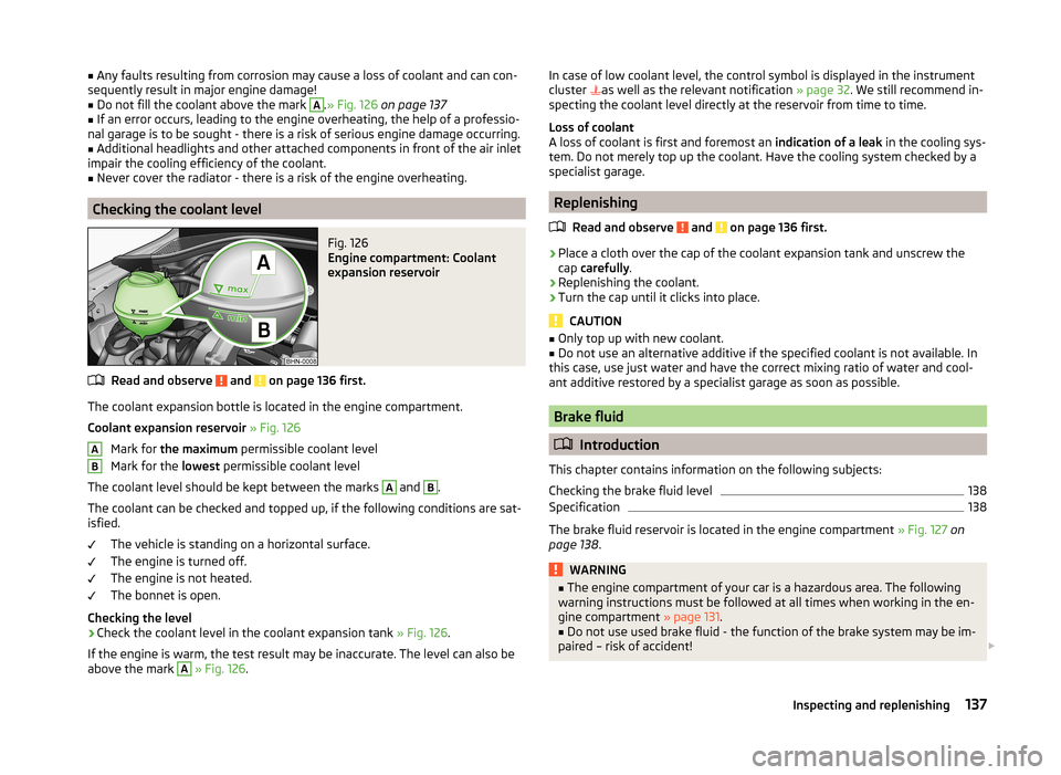
Fig. 126
Engine compartment: Coolant
expansion reservoir
Read and observe and on page 136 first.
The coolant expansion bottle is located in the engine compartment.
Coolant expansion reservoir » Fig. 126
Mark for the maximum permissible coolant level
Mark for the lowest permissible coolant level
The coolant level should be kept between the marks
A
and
B
.
The coolant can be checked and topped up, if the following conditions are sat-
isfied.
The vehicle is standing on a horizontal surface.
The engine is turned off.
The engine is not heated.
The bonnet is open.
Checking the level
›
Check the coolant level in the coolant expansion tank » Fig. 126.
If the engine is warm, the test result may be inaccurate. The level can also be
above the mark
A
» Fig. 126 .
ABIn case of low coolant level, the control symbol is displayed in the instrument
cluster as well as the relevant notification » page 32. We still recommend in-
specting the coolant level directly at the reservoir from time to time.
Loss of coolant
A loss of coolant is first and foremost an indication of a leak in the cooling sys-
tem. Do not merely top up the coolant. Have the cooling system checked by a
specialist garage.
Replenishing
Read and observe
and on page 136 first.
›
Place a cloth over the cap of the coolant expansion tank and unscrew the
cap carefully .
›
Replenishing the coolant.
›
Turn the cap until it clicks into place.
CAUTION
■
Only top up with new coolant.■Do not use an alternative additive if the specified coolant is not available. In
this case, use just water and have the correct mixing ratio of water and cool-
ant additive restored by a specialist garage as soon as possible.
Brake fluid
Introduction
This chapter contains information on the following subjects:
Checking the brake fluid level
138
Specification
138
The brake fluid reservoir is located in the engine compartment » Fig. 127 on
page 138 .
WARNING■
The engine compartment of your car is a hazardous area. The following
warning instructions must be followed at all times when working in the en-
gine compartment » page 131.■
Do not use used brake fluid - the function of the brake system may be im-
paired – risk of accident!
137Inspecting and replenishing
Page 140 of 193

CAUTION■Do not continue your journey if the fluid level has dropped below the “MIN”
marking » Fig. 127 on page 138 , do not continue to drive - risk of accidents!
Seek help from a specialist garage.■
Brake fluid damages the paintwork of the vehicle.
Note
■ The brake fluid is changed as part of a compulsory inspection service.■We recommend using brake fluids from the ŠKODA Original Accessories
range.
Checking the brake fluid level
Fig. 127
Engine compartment: Brake fluid
reservoir
Read and observe and on page 137 first.
The fluid can be checked if the following conditions are met.
The vehicle is standing on a horizontal surface.
The engine is turned off.
The bonnet is open.
Checking the level
›
Check the level of brake fluid in the reservoir » Fig. 127.
The level must be between the “MIN” and “MAX” markings.
A slight drop in the fluid level results when driving due to normal wear-and-
tear and automatic adjustment of the brake pads.
There may be an indication of a leak in the brake system, however, if the fluid
level drops significantly within a short time or if it drops below the “MIN” mark-
ing.
Too low brake fluid level is indicated by the warning light lighting up in the
instrument cluster as well as the relevant notification being dis-
played » page 31 ,
Brake system .
Specification
Read and observe
and on page 137 first.
The brake fluid must comply with the following standards or specifications:› VW 50114;
› FMVSS 116 DOT4.
Vehicle battery
Introduction
This chapter contains information on the following subjects:
Opening the cover
139
Checking the battery electrolyte level
140
Charging
140
Replacing
141
Disconnecting and reconnecting
141
Automatic load deactivation
141
The vehicle battery represents a power source for the motor to start and for
the supply of electrical consumers in the car.
Warning symbols on the vehicle battery
SymbolMeaningAlways wear eye protection!Battery acid is severely caustic. Always wear gloves and eye pro-
tection!Keep fire, sparks, open flames and lit cigarettes well clear of the
vehicle battery!When charging the vehicle battery, a highly explosive gas mixture
is produced!Keep children away from the vehicle battery! 138General Maintenance
Page 142 of 193

Checking the battery electrolyte levelFig. 129
Vehicle battery: Electrolyte level
indicator
Read and observe and on page 139 first.
On vehicles with a vehicle battery fitted with a colour indicator, » Fig. 129the
colouring of the display can indicate the acidic level.
Air bubbles can influence the colour of the indicator. For this reason carefully knock on the indicator before carrying out the check.
› Black colour – electrolyte level is correct.
› Colourless or light yellow colour – electrolyte level too low, the battery must
be replaced.
Vehicles with a START-STOP system are fitted with a battery control unit for
checking the energy level for the recurring engine start.
We recommend that you have the acid level checked regularly by a specialist garage, especially in the following cases.
› High external temperatures.
› Longer day trips.
› After each charge.
Winter time
The vehicle battery only has a proportion of the starting power in lower tem-
peratures. A discharged vehicle battery may already freeze at temperatures
just below 0 °C .
We therefore recommend that you have the battery checked and, if necessary,
recharged by a specialist garage before the start of the winter.
Note■ The battery acid level is also checked regularly by a specialist garage as part
of the inspection service.■
For technical reasons, on vehicles with the description “AGM”, the electrolyte
level cannot be checked.
Charging
Read and observe
and on page 139 first.
A properly charged vehicle battery is essential for reliably starting the engine.
A charging operation can be performed if the following conditions are satis-
fied.
The engine is turned off.
The ignition is switched off.
All consumers are turned off.
The bonnet is open.
“Fast charging” with high currents
›
Disconnect both battery cables (first of all “negative”, then “positive”).
›
Attach the terminal clamps of the charger to the battery terminals (red =
“positive”, black = “negative”).
›
Plug the mains cable of the charger into the power socket and switch on the
device.
›
After charging has been successful: Switch off the charger and remove the
mains cable from the power socket.
›
Only then disconnect the charger's terminal clamps.
›
Reconnect the cables to the battery (first “positive”, then “negative”).
Charging with low voltages
It is not necessary to disconnect the cables from the battery if you recharge
the vehicle battery, for example from a mini-charger.
Refer to the instructions of the charger manufacturer .
A charging current of 0.1 multiple of the total vehicle battery capacity (or low-
er) must be used until full charging is achieved.
The vent plugs of the vehicle battery should not be opened for charging.
140General Maintenance
Page 143 of 193
WARNING■When you charge a battery, hydrogen is released, and a highly explosive
gas mixture is also produced. An explosion can be caused through sparkling
over during unclamping or loosening of the cable plug while the ignition is
on.■
Creating a bridge between the poles on the battery (e.g. with metal ob-
jects - cables) creates a short circuit - risk of damage to the battery, explo-
sion and burning of the battery, jets of acid spurting out.
■
Avoid creating sparks when working with cables and electrical devices.
Strong sparking represents a risk of injury.
■
Before carrying out any work on the electrical system, switch off the en-
gine, the ignition and all electrical consumers and disconnect the negative
terminal (-).
■
“Quick-charging” the vehicle battery is dangerous and requires a special
charger and specialist knowledge.
■
We therefore recommend that vehicle batteries be “rapidly charged” by a
specialist garage.
CAUTION
On vehicles with the START-STOP system, the pole terminal of the charger
must not be connected directly to the negative terminal of the vehicle battery,
but only to the engine earth » page 158, Jump-starting in vehicles with the
START-STOP system .
Replacing
Read and observe
and on page 139 first.
The new vehicle battery must have the same capacity, voltage, current and
size as the original battery. Suitable vehicle battery types can be purchased
from a specialist garage.
We recommend having the battery replaced by a specialist garage, where the
new vehicle battery will be installed properly and the original battery will be
disposed of in accordance with national regulations.
Disconnecting and reconnecting
Read and observe
and on page 139 first.
Disconnecting
›
Switch off the ignition.
›First, disconnect the negative terminal (-) first, then the positive (+) terminal
of the battery.
Connecting›
First, connect the positive (+) first, then the negative (-) battery terminal.
After disconnecting and re-connecting the vehicle battery, the following func-
tions or devices are partially or completely inoperative.
Function / deviceCommissioningRadio and/or navigation systemEnter code number » User radio
manual and/or » navigation
system user manualTime settings» page 29
CAUTION
■ Disconnect the vehicle battery only with the ignition turned off - there is a
risk of damaging the electrical system of the vehicle.■
Under no circumstances must the battery cables be connected incorrectly –
risk of a cable fire.
Note
■ After disconnecting and re-connecting the vehicle battery, we recommend
having the vehicle checked by a specialist to ensure that the full functionality
of all electrical systems is guaranteed.■
The data of the multi-function display will be reset.
Automatic load deactivation
Read and observe
and on page 139 first.
The vehicle voltage control unit automatically prevents the battery from dis-
charging when the battery is put under high levels of strain. This manifests it-
self by the following.
› The idling speed is raised to allow the generator to deliver more electricity to
the electrical system.
› Where necessary, large convenience consumers such as seat heaters and
rear window heaters have their power limited or are shut off completely in
the event of an emergency.
141Inspecting and replenishing
Page 144 of 193
CAUTION■Despite such intervention by the vehicle electric system management, the
vehicle battery may be drained. For example, when the ignition is switched on
a long time with the engine turned off or the side or parking lights are turned
on during longer parking.■
Consumers that are supplied via a 12-V power socket can cause the vehicle
battery to discharge when the ignition is switched off.
Note
Driving comfort is not impaired by consumers being deactivated. The driver is
often not aware of it having taken place.Wheels
Tyres and wheel rims
Introduction
This chapter contains information on the following subjects:
Service life of tyres
143
New tyres
144
Unidirectional tyres
145WARNINGThe national legal regulations must be observed for the use of tyres.WARNINGInstructions for the use of tyres■For the first 500 km, new tyres do not yet provide optimum grip, and ap-
propriate care should therefore be taken when driving – risk of accident!■
Only use radial tyres of the same type, size (rolling circumference) and
tread pattern on all four wheels.
■
For reasons of driving safety, do not replace tyres individually.
■
Never exceed the maximum permissible load bearing capacity of moun-
ted tyres.
■
Never exceed the maximum permissible speed for the mounted tyres.
■
An incorrect wheel alignment at the front or rear impairs handling.
■
Unusual vibrations or pulling of the vehicle to one side could be a sign of
tyre damage. If there is any suspicion that a wheel is damaged, immediately
reduce your speed and stop! If no external damage is evident, drive slowly
and carefully to the nearest specialist garage to have the vehicle checked.
■
Only use tyres or wheel rims that have been approved by ŠKODA for your
model of vehicle. Failure to observe this instruction will adversely affect the
road safety of your vehicle.
WARNINGInformation regarding tyre damage or wear■Never use tyres if you do not know anything about the condition and age.■
Never drive with damaged tyres.
■
Immediately replace damaged wheel rims or tyres.
142General Maintenance
Page 158 of 193

Inflation hose with plug
Air compressor
Button for releasing the tyre pressure
12 volt cable connector
Tyre inflation hose
Tyre inflation pressure indicator
ON and OFF switch
Tyre inflater bottle with sealing agent
Replacement valve core
The valve remover 2
has a slot at its lower end which fits into the valve core.
Preparations for using the breakdown kit
Read and observe
on page 155 first.
Always change a wheel on a level surface as far as possible.
The following preparatory work must be carried out before using the break-
down kit.
›
Have all of the occupants get out of the vehicle. While changing a tyre, the
occupants of the vehicle should not stand on the road (they should instead
remain behind a crash barrier).
›
Switch off the engine.
›
Move the gear shift lever into Neutral or move the selector lever for the au-
tomatic gearbox into position P.
›
Firmly apply the handbrake.
›
Check that you can carry out the repairs with the breakdown kit » page 155.
›
Uncouple any trailers.
›
Remove the breakdown kit from the boot.
›
Stick the sticker
1
» Fig. 143 on page 155 on the dashboard in the driver's
field of view.
›
Do not remove the foreign body, e.g. screw or nail, from the tyre.
›
Unscrew the valve cap.
›
Use the valve remover
2
to unscrew the valve core and place it on a clean
surface (rag, paper, etc.).
34567891011Sealing and inflating the tyre
Read and observe
on page 155 first.
Sealing
›
Forcefully shake the tyre inflater bottle
10
» Fig. 143 on page 155 back and
forth several times.
›
Firmly screw the inflation hose
3
onto the tyre inflater bottle
10
in a clock-
wise direction. The film on the cap is pierced automatically.
›
Remove the plug from the inflation hose
3
and plug the open end fully onto
the tyre valve.
›
Hold the bottle
10
with the bottom facing upwards and fill all of the sealing
agent from the tyre inflater bottle into the tyre.
›
Remove the empty tyre inflater bottle from the valve.
›
Screw the valve core back into the tyre valve using the valve remover
2
.
Inflating
›
Screw the tyre inflation hose
7
» Fig. 143 on page 155 of the air compressor
firmly onto the tyre valve.
›
Start the engine and run it in idle.
›
Plug the connector
6
into 12 Volt socket » page 71, 12-Volt power outlet .
›
Switch on the air compressor with the ON and OFF switch
9
.
›
Allow the air compressor to run until a pressure of 2.0-2.5 bar is achieved.
Maximum run time of 8 minutes »
›
Switch off the air compressor.
›
If you cannot reach an air pressure of 2.0–2.5 bar, unscrew the tyre inflation
hose
7
from the tyre valve.
›
Drive the vehicle 10 metres forwards or backwards to allow the sealing agent
to “distribute” in the tyre.
›
Firmly screw the tyre inflation hose
7
back onto the tyre valve and repeat
the inflation process.
›
If you cannot reach the required tyre inflation pressure here either, this
means the tyre has sustained too much damage. You cannot seal with tyre with the breakdown kit »
.
›
Switch off the air compressor.
›
Remove the tyre inflation hose
7
from the tyre valve.
Once a tyre inflation pressure of 2.0–2.5 bar is achieved, continue the journey
at a maximum speed of 80 km/h (50 mph).
Check the tyre inflation pressure after driving for 10 minutes » page 157.
156Do-it-yourself