key SKODA RAPID SPACEBACK 2013 1.G Owner's Guide
[x] Cancel search | Manufacturer: SKODA, Model Year: 2013, Model line: RAPID SPACEBACK, Model: SKODA RAPID SPACEBACK 2013 1.GPages: 193, PDF Size: 14.8 MB
Page 87 of 193

Air outlet ventsFig. 90
Air outlet vents
Read and observe
and on page 84 first.
Warmed, not warmed fresh or cooled air will flow out of the opened air outlet
vents according to the setting of the control and the outside atmospheric con-
ditions.
The direction of airflow can be adjusted using the air outlet vents 3 and
4 » Fig. 90 and the outlets can also be opened and closed individually.
Changing the air flow direction
›
To change the height of the air flow, turn the horizontal fins upward or
downward using the movable adjuster
A
» Fig. 90 .
›
To adjust the lateral direction of the air flow, turn the vertical fins with the
movable adjuster
A
to the left or to the right.
Open/close
›
Turn the regulator
B
» Fig. 90 upwards or downwards.
An overview of the available settings for adjusting the direction of the air
outlet.Set the direction of the air outletActive air outlet vents1, 2 , 41, 2 , 4 , 54 , 53 , 4
Note
Do not cover the air outlet vents with objects of any kind.
Air distribution control
Read and observe
and on page 84 first.
Recirculated air mode mostly prevents polluted air outside the vehicle from
getting into the vehicle, for example when driving through a tunnel or when
standing in a traffic jam.
In recirculated air mode air is sucked out of the interior of the vehicle and then
fed back into the interior.
Heating and air conditioning (manual air conditioning)
To turn the recirculation mode on or off, press the Symbol key
.
The air recirculation mode is automatically turned off by turning the air distri-
bution control
C
to position
» Fig. 91 on page 86 or » Fig. 92 on page 86 .
Recirculated air mode can be switched on again from this setting by repeatedly
pressing the symbol button .
Climatronic (automatic air conditioning)
To switch on press the Symbol key
. The symbol
(pos.
7
» Fig. 93 on
page 87 ) appears in the display.
To switch off press the symbol key
again. The
symbol in the display
goes out.
85Heating and air conditioning
Page 89 of 193

Set the direction of the air outlet » page 85
›
Air flow to the windows
›
Air flow to the upper body
›
Air flow in the footwell
›
Airflow over the windows and into the footwell
Switch recirculation on/off » page 85
Switch the cooling system on/off
Note
■ The warning light in the button lights up after activation, even if not all of
the conditions for the function of the cooling system have been met. By light-
ing up of the warning light in the button, the operational readiness of the cool-
ing system is signalled.■
During operation of the air conditioning, an increase in engine idle speed may
occur under certain circumstances in order to ensure sufficient heating com-
fort.
Climatronic (automatic air conditioning)
Fig. 93
Controls the Climatronic
Read and observe
and on page 84 first.
The Climatronic in automatic mode ensures the best-possible setting of the
temperature of the outflowing air, the blower stage and air distribution.
The system also takes sunlight into account, which eliminates the need to al-
ter the settings manually afterwards.
Individual functions can be set off or on by turning the knob or pressing the
respective button. When switched on, the display shows the corresponding
icon appears.
CFunctions of the various controls and display » Fig. 93
Setting temperature ›
Lower temperature
›
Increase temperature
Selected temperature
Degrees Celsius or Fahrenheit
Automatic operation of the air conditioning system
Intensive windshield defroster switched on
Direction of air flow
Recirculated air mode activated
Cooling system activated
Set blower speed
Set the temperature (turn to the left: Reduce fan speed, turn to the right:
Increase blower speed)
Interior temperature sensor Switching automatic mode on Switching the intensive windshield defroster on/off (when this function
is switched on, the warning light illuminates in the button)
Air flow to the windows
Air flow to the upper body
Air flow in the footwell
Switch recirculation on/off » page 85
Switch the cooling system on/off
After the cooling system is switched off, only the ventilation function remains active, whereby the lowest temperature that can be reached is the outside
temperature.
Setting temperature
The set temperature value appears in the display (pos. 2
» Fig. 93 ).
To switch between degrees Celsius and degrees Fahrenheit , the keys
and are to be pressed and held simultaneously.
The information appears in the display in the desired temperature measuring
unit (pos.
3
» Fig. 93 ).
The interior temperature can be set between +18 °C and +29 ℃. The interior
temperature is regulated automatically within this range.
If you select the temperature below +18 ℃, “LO” appears in the display.
123456789101187Heating and air conditioning
Page 94 of 193
›If the hands-free system announces (as standard
SKODA_BT) on the display
of the mobile phone, enter the PIN 1)
within 30 seconds and wait, until the
connection is established 2)
.›
To finish pairing in the MAXI DOT display, confirm the creation of the new
user profile.
If there is no free space available to create a new user profile, delete an exist- ing user profile.
During the connecting procedure, no other mobile phone may be connected
with the hands-free system.
Up to four mobile phones can be paired with the hands-free system, whereby
only one mobile phone can communicate with the hands-free system.
The visibility of the hands-free system is automatically switched off 3 minutes
after the ignition is switched on and is also deactivated when the mobile
phone has connected to the hands-free system.
Restoring the visibility of the hands-free system
If you have not managed to connect your mobile phone with the hands-free
system within 3 minutes of switching on the ignition, the visibility of the
hands-free system can be re-established for 3 minutes in one of the following
ways.
› By turning the ignition off and on.
› By turning voice control off and on.
› In the MAXI DOT display under menu item
Bluetooth - Visibility .
Creating a connection with an already paired mobile phone
After switching on the ignition, the connection is automatically established for
the already paired mobile phone 2)
. Check on your mobile phone if the automatic
connection has been established.
Disconnecting the connection
The connection to a connected mobile phone can be ended in the following
ways.
› By withdrawing the ignition key.
› By disconnecting the hands-free system in the mobile phone.
› By disconnecting from the user in the MAXI DOT display under the menu item
Bluetooth - User .
Solving connection problems
If the hands-free system reports No paired phone found, check the operating
status of the mobile phone.
› Is the mobile phone switched on?
› Is the PIN code entered?
› Is Bluetooth ®
active?
› Is the visibility of the mobile phone active?
› Has the mobile phone already been paired with the hands-free system?
Telephone operation in the MAXI DOT display
Read and observe
on page 89 first.
The following menu items can be selected from the Phone menu.
› Phone book
› Dial number 3)
› Call register
› Voice mailbox
› Bluetooth 3)
› Settings 4)
› Back
Phone book
The Phone book menu item lists the contacts downloaded from the telephone
memory and the mobile phone SIM card.
1)
Depending on the Bluetooth®
version on the mobile phone, an automatically generated 6-digit PIN (SSP)
is either displayed, or the PIN 1234 has to be entered manually.
2)
Some mobile phones have a menu, in which the authorisation for establishing a Bluetooth ®
connection
is completed by inputting a PIN number. If the authorisation input is required, it must always be per-
formed when re-establishing the Bluetooth connection.
3)
On vehicles fitted with the Amundsen+ navigation system, this function can be accessed via the naviga-
tion system menu; refer to the » operating instructions for the Amundsen+ navigation system .
4)
This function is not available in vehicles fitted with the Amundsen+ navigation system.
92Using the system
Page 99 of 193
Driving
Starting-off and Driving
Starting and turning off the engine
Introduction
This chapter contains information on the following subjects:
Electronic immobilizer
97
Lock/unlock steering lock
97
Switch on the ignition and start the engine
98
Switching off the engine
98
With the key in the ignition, the ignition can be switched on and off and the
engine can be started / stopped.
WARNING■ While driving with the engine stopped, the ignition must always be
switched on » page 98, Switch on the ignition and start the engine .
■ With the ignition off, the steering may lock » page 97 - danger of an
accident!■
Do not withdraw the ignition key from the ignition lock until the vehicle
has come to a stop » page 100, Parking . Otherwise, the steering could be
blocked – risk of accident!
■
Never leave the key in the vehicle when you exit the vehicle. Unauthor-
ized persons, such as children, for example, could lock the car, turn on the
ignition or start the engine - there is a danger of injury and accidents!
■
Never leave the vehicle unattended with the engine running - there is
risk of accident, damage or theft!
■
Never switch off the engine before the vehicle is stationary – risk of acci-
dent!
WARNING■ Never (e.g. in garages) run the engine in a closed place - there is the dan-
ger of poisoning and death!■
Do not leave any items (e.g. cloths or tools) in the engine compartment.
This presents a fire hazard and the risk of engine damage.
■
Never cover the engine with additional insulation material (e.g. with a
cover) – risk of fire!
CAUTION■ Only start the engine when the engine and the vehicle are stationary - there
is a danger of starter and engine damage!■
Do not tow start the engine – there is a risk of damaging the engine and the
catalytic converter! The battery from another vehicle can be used as a jump-
start aid » page 157 .
Note
Do not warm up the engine while the vehicle is stationary. If possible, start
your journey as soon as the engine has started. Through this, the engine rea-
ches its operating temperature faster.
Electronic immobilizer
Read and observe
and on page 97 first.
The electronic immobilizer makes a possible attempted theft or unauthorized
use of your vehicle more difficult.
An electronic chip is integrated in the head of the key. The immobiliser is deac-
tivated with the aid of this chip when the key is inserted in the ignition lock.
The electronic immobiliser is automatically activated when the ignition key is
withdrawn from the lock.
The engine will not start if a non-authorized ignition key is used.
The following message is shown in the information cluster display. Immobilizer active.
IMMOBILIZER
Lock/unlock steering lock
Read and observe
and on page 97 first.
The steering lock (steering lock) deters any attempted theft of your vehicle.
Locking
›
Withdraw the ignition key.
›
Turn the steering wheel to the left or right until the steering lock clicks into
place.
Unlocking
›
Insert the key into the ignition lock.
›
Switch on the ignition » page 98.
97Starting-off and Driving
Page 100 of 193
The vehicle is unlocked.
If the ignition switch cannot be turned on, then turn the steering wheel back
and forth slightly and thereby unlock the steering lock.
Switch on the ignition and start the engine
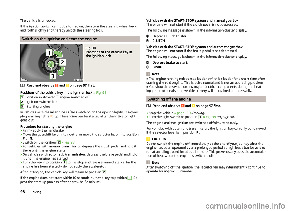
Fig. 98
Positions of the vehicle key in
the ignition lock
Read and observe and on page 97 first.
Positions of the vehicle key in the ignition lock » Fig. 98
Ignition switched off, engine switched off
Ignition switched on
Starting engine
In vehicles with diesel engines after switching on the ignition lights, the glow
plug warning lights up. The engine can be started after the indicator light
goes out.
Procedure for starting the engine
›
Firmly apply the handbrake.
›
Move the gearshift lever into neutral or move the selector lever into position
P or N.
›
Switch on the ignition
2
» Fig. 98 .
›
For vehicles with manual transmission depress the clutch pedal and hold it
there until the engine starts.
›
On vehicles with automatic transmission, depress the brake pedal and hold
it until the engine has started.
›
Turn the key into position
3
to the stop and release immediately after the
engine has been started – do not apply the accelerator.
After letting go, the vehicle key will return to position
2
.
If the engine does not start within 10 seconds, turn the key to position
1
. Re-
peat the start-up process after approx. half a minute.
123Vehicles with the START-STOP system and manual gearbox
The engine will not start if the clutch pedal is not depressed.
The following message is shown in the information cluster display. Depress clutch to start.
CLUTCH
Vehicles with the START-STOP system and automatic gearbox
The engine will not start if the brake pedal is not depressed.
The following message is shown in the information cluster display. Depress brake to start.
BRAKE
Note
■ The engine running noises may louder at first be louder for a short time after
starting the cold engine. This is quite normal and is not an operating problem.■
You should not switch on any major electrical components during the heat-
ing period otherwise the vehicle battery will be drained unnecessarily.
Switching off the engine
Read and observe
and on page 97 first.
›
Stop the vehicle » page 100, Parking .
›
Turn the light switch to position
1
» Fig. 98 on page 98 .
The engine and the ignition are switched off simultaneously.
For vehicles with automatic transmission, the ignition key can only be removed
if the selector lever is in position P .
CAUTION
Do not switch the engine off immediately at the end of your journey after the
engine has been operated over a prolonged period at high loads but leave it to
run at an idling speed for about 1 minute. This prevents any possible accumula-
tion of heat when the engine is switched off.
Note
After switching off the ignition, the radiator fan may intermittently continue to
operate for approx. 10 minutes.98Driving
Page 104 of 193
CAUTION■If the selector lever is moved to mode N while driving, the accelerator pedal
must be released and you will need to wait until the engine has reached its
idling speed before moving the selector lever to a forward driving mode again.■
When the outdoor temperature is below -10 ° C, the selector lever, when
starting, must always be in P mode.
■
When stopping on a slope, never try to keep the vehicle in position by using
the accelerator pedal – this may lead to gear damage.
Note
After the ignition is switched off, the ignition key can only be withdrawn if the
selector lever is in the position P.
Modes and use of selector lever
Fig. 101
Selector lever/display
Fig. 102
Shift lock button
Read and observe and on page 101 first.
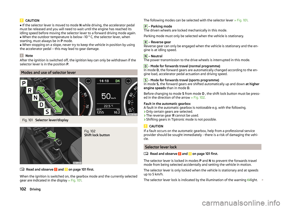
When the ignition is switched on, the gearbox mode and the currently selected
gear are indicated in the display » Fig. 101.
The following modes can be selected with the selector lever » Fig. 101.P
– Parking mode
The driven wheels are locked mechanically in this mode.
Parking mode must only be selected when the vehicle is stationary.
R
– Reverse gear
Reverse gear can only be engaged when the vehicle is stationary and the en-
gine is at idling speed.
N
– Neutral
The power transmission to the drive wheels is interrupted in this mode.
D
- Mode for forwards travel (normal programme)
In mode D, the forward gears are automatically changed according to the en-
gine load, accelerator pedal actuation and driving speed.
S
- Mode for forwards travel (sports programme)
In mode S, the forward gears are shifted automatically up and down at higher
engine speeds than in mode D.
Before changing to mode S from mode D , the shift lock button must be press-
ed in the direction of the arrow » Fig. 102.
Fault in the automatic gearbox
A fault in the automatic gearbox is noticeable e.g. with the following.
› Only certain gears are selected.
› The reverse gear
R cannot be used.
› Shifting gears in Tiptronic mode is not possible.
CAUTION
If a fault occurs on the automatic gearbox, help from a professional service
provider should be sought immediately - there is a risk of damaging the vehi-
cle.
Selector lever lock
Read and observe
and on page 101 first.
The selector lever is locked in modes P and N to prevent the forwards travel
mode from being selected accidentally and setting the vehicle in motion.
The selector lever is only locked when the vehicle is stationary and at speeds
up to 5 km/h.
The selector lever lock is indicated by the illumination of the warning light.
102Driving
Page 108 of 193
Assist systems
Braking and stabilisation systems
Introduction
This chapter contains information on the following subjects:
Electronic Stability Control (ESC)
106
Anti-lock Braking System (ABS)
106
Traction Control System (TCS)
106
Electronic Differential Lock (EDL)
107
Hydraulic Brake Assist (HBA)
107
Hill Hold Control (HHC)
107
This chapter deals with the functions of the braking and stabilisation systems,
with the error indicator referred to in chapter » page 30, Indicator lights .
The braking and stabilisation systems are automatically activated each time
the ignition is switched on.
WARNING■ A lack of fuel can cause irregular engine running or cause the engine to
shut down. The brake assist systems would then fail to function – risk of
accident!■
The increased safety provided by the brake assist systems must not
tempt you to take safety risks – risk of accident!
■
Adjust the speed and driving style to the current visibility, weather, road
and traffic conditions.
Electronic Stability Control (ESC)
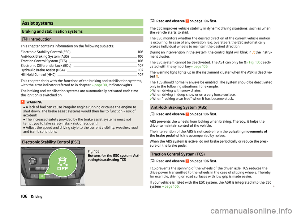
Fig. 105
Buttons for the ESC system: Acti-
vating/deactivating TCS
Read and observe on page 106 first.
The ESC improves vehicle stability in dynamic driving situations, such as when the vehicle starts to skid.
The ESC monitors whether the desired direction of the current vehicle motion
is occurring. In case of any deviation (e.g. oversteer), the ESC automatically
brakes individual wheels to maintain the desired direction.
During an intervention in the system, the control light will blink in
the instru-
ment cluster.
The ESC system cannot be deactivated. The AST can only be
» Fig. 105 deacti-
vated with the symbol key » page 106.
The warning light lights up in the instrument cluster when the ASR is deactiva- ted .
The TCS should normally always be enabled. The system should be deactivated
only in the following situations, for example.
› When driving with snow chains.
› When driving in deep snow or on a very loose surface.
› When “rocking a car free” when it has become stuck.
Anti-lock Braking System (ABS)
Read and observe
on page 106 first.
ABS prevents the wheels from locking when braking. Thereby, it helps the
driver to maintain control of the vehicle.
The intervention of the ABS is noticeable from the pulsating movements of
the brake pedal which is accompanied by noises.
When the ABS system is active, do not brake periodically or reduce the pres-
sure on the brake pedal.
Traction Control System (TCS)
Read and observe
on page 106 first.
TCS prevents the spinning of the wheels of the driven axle. TCS reduces thedrive power transmitted to the wheels in the case of slipping wheels. Thereby,
for example, driving on road surfaces with low grip is made easier.
If your vehicle is fitted with the ESC system, the ASR is integrated into the ESC
system » page 106 .
106Driving
Page 114 of 193

Hitch and trailer
Hitch
Introduction
This chapter contains information on the following subjects:
Description
112
Adjusting the ready position
113
Fitting the ball head
113
Check proper fitting
114
Removing the ball head
115
Use and care
115
If your vehicle has already been factory-fitted with a towing device or is fitted
with a towing device from ŠKODA Original Accessories, then it meets all of the
technical requirements and national legal regulations for towing a trailer.
Your vehicle is fitted with a 13-pin power socket for the electrical connection
between the vehicle and trailer. If the trailer that is to be towed has a 7-pin
connector , you can use a suitable adapter from ŠKODA Original Accessories.
The maximum trailer drawbar load is 50 kg.
WARNING■
Check that the tow bar is seated correctly and is secured in the mounting
recess before the start of every journey.■
Do not use the tow bar if it is not correctly inserted and secured in the
mounting recess.
■
Do not use the towing device if it is damaged or if there are parts missing.
■
Do not modify or adapt the towing device in any way.
■
Never release the tow bar while the trailer is still coupled.
CAUTION
Take care when handling the tow bar so as to avoid damaging the paintwork
on the bumper.
Note
Tow the vehicle by means of the detachable ball rod » page 160.DescriptionFig. 110
Carrier for the towing device / tow bar
Read and observe
and on page 112 first.
The tow bar can be removed and is located in the spare wheel compartment or
in a compartment for the spare wheel in the boot » page 150.
Support for the towing device and tow bar » Fig. 110
13-pin power socket
Safety eyelet
Mounting recess
Cap
Protective cap
Ball head
Locking ball
Centring
Green marking on the hand wheel
Hand wheel
Key
Lock cap
Red marking on the hand wheel
White marking on ball head
Note
On the bottom of the key is a code number. If you lose a key, please contact a
specialist garage which will be able to use this code number to provide you
with a new one.1234567891011121314112Driving
Page 115 of 193

Adjusting the ready positionFig. 111
Setting the ready position
Fig. 112
Ready position
Read and observe
and on page 112 first.
Always adjust the ball head in the ready position before fitting.
›
Turn the key
A
in direction of the arrow
1
to the stop » Fig. 111.
›
Pull the hand wheel
B
in the direction of the arrow
2
and turn in the direc-
tion of the arrow
3
to the stop.
The hand wheel remains locked in this position.
Correctly adjusted standby position » Fig. 112
The key
C
is in the unlocked position - the arrow on the key points to the
“padlock open” icon . The key cannot be removed.
The locking balls
D
can be pushed fully into the tow bar.
The red marking E on the hand wheel points to the white marking on the
ball bar.
There is a clear gap of approx. 4 mm F
between the hand wheel and the
tow bar.
The ball bar is thus set ready for installation.
WARNINGIf the tow bar cannot be correctly placed in the ready position, then it must
not be used.
CAUTION
When in the ready position, the key cannot be removed from the hand wheel
lock.
Fitting the ball head
Fig. 113
Insert the ball bar / lock the lock and remove the key
113Hitch and trailer
Page 116 of 193
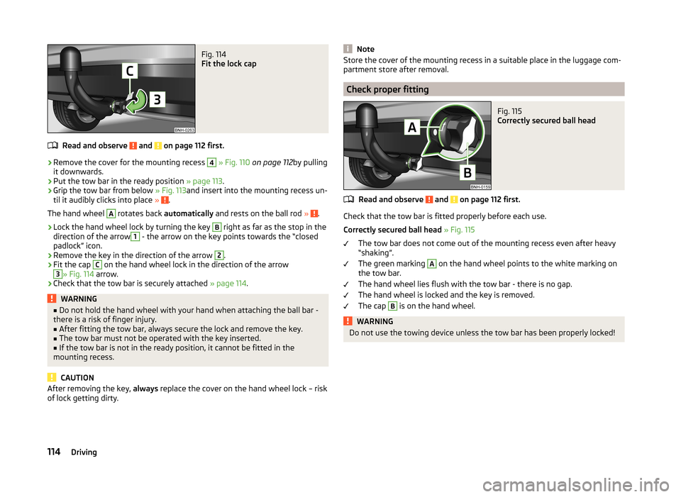
Fig. 114
Fit the lock cap
Read and observe and on page 112 first.
›
Remove the cover for the mounting recess
4
» Fig. 110 on page 112 by pulling
it downwards.
›
Put the tow bar in the ready position » page 113.
›
Grip the tow bar from below » Fig. 113and insert into the mounting recess un-
til it audibly clicks into place » .
The hand wheel
A
rotates back automatically and rests on the ball rod » .
›
Lock the hand wheel lock by turning the key
B
right as far as the stop in the
direction of the arrow
1
- the arrow on the key points towards the “closed
padlock” icon.
›
Remove the key in the direction of the arrow
2
.
›
Fit the cap
C
on the hand wheel lock in the direction of the arrow
3
» Fig. 114 arrow.
›
Check that the tow bar is securely attached » page 114.
WARNING■
Do not hold the hand wheel with your hand when attaching the ball bar -
there is a risk of finger injury.■
After fitting the tow bar, always secure the lock and remove the key.
■
The tow bar must not be operated with the key inserted.
■
If the tow bar is not in the ready position, it cannot be fitted in the
mounting recess.
CAUTION
After removing the key, always replace the cover on the hand wheel lock – risk
of lock getting dirty.NoteStore the cover of the mounting recess in a suitable place in the luggage com-
partment store after removal.
Check proper fitting
Fig. 115
Correctly secured ball head
Read and observe and on page 112 first.
Check that the tow bar is fitted properly before each use.
Correctly secured ball head » Fig. 115
The tow bar does not come out of the mounting recess even after heavy
“shaking”.
The green marking
A
on the hand wheel points to the white marking on
the tow bar.
The hand wheel lies flush with the tow bar - there is no gap.
The hand wheel is locked and the key is removed.
The cap
B
is on the hand wheel.
WARNINGDo not use the towing device unless the tow bar has been properly locked!114Driving