buttons SKODA RAPID SPACEBACK 2013 1.G Owner's Manual
[x] Cancel search | Manufacturer: SKODA, Model Year: 2013, Model line: RAPID SPACEBACK, Model: SKODA RAPID SPACEBACK 2013 1.GPages: 193, PDF Size: 14.8 MB
Page 27 of 193
Using the system
Cockpit
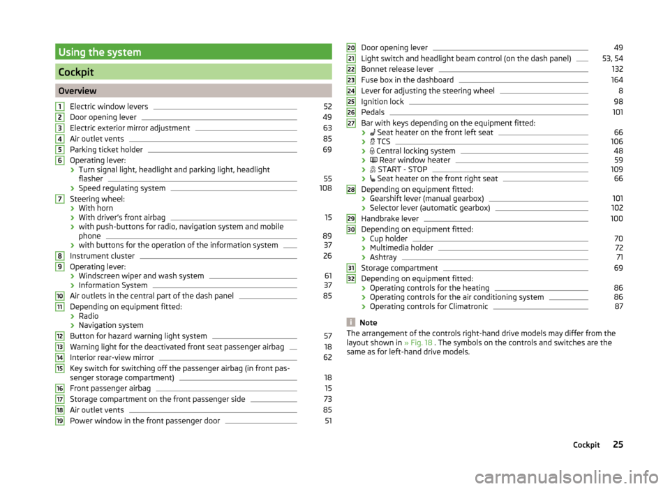
OverviewElectric window levers
52
Door opening lever
49
Electric exterior mirror adjustment
63
Air outlet vents
85
Parking ticket holder
69
Operating lever:
› Turn signal light, headlight and parking light, headlight
flasher
55
› Speed regulating system
108
Steering wheel:
› With horn
› With driver’s front airbag
15
›with push-buttons for radio, navigation system and mobile
phone
89
› with buttons for the operation of the information system
37
Instrument cluster
26
Operating lever:
› Windscreen wiper and wash system
61
›Information System
37
Air outlets in the central part of the dash panel
85
Depending on equipment fitted:
› Radio
› Navigation system
Button for hazard warning light system
57
Warning light for the deactivated front seat passenger airbag
18
Interior rear-view mirror
62
Key switch for switching off the passenger airbag (in front pas-
senger storage compartment)
18
Front passenger airbag
15
Storage compartment on the front passenger side
73
Air outlet vents
85
Power window in the front passenger door
5112345678910111213141516171819Door opening lever49
Light switch and headlight beam control (on the dash panel)
53, 54
Bonnet release lever
132
Fuse box in the dashboard
164
Lever for adjusting the steering wheel
8
Ignition lock
98
Pedals
101
Bar with keys depending on the equipment fitted:
›
Seat heater on the front left seat
66
›
TCS
106
›
Central locking system
48
›
Rear window heater
59
›
START - STOP
109
›
Seat heater on the front right seat
66
Depending on equipment fitted:
› Gearshift lever (manual gearbox)
101
›Selector lever (automatic gearbox)
102
Handbrake lever
100
Depending on equipment fitted:
› Cup holder
70
›Multimedia holder
72
›Ashtray
71
Storage compartment
69
Depending on equipment fitted:
› Operating controls for the heating
86
›Operating controls for the air conditioning system
86
›Operating controls for Climatronic
87
Note
The arrangement of the controls right-hand drive models may differ from the
layout shown in » Fig. 18 . The symbols on the controls and switches are the
same as for left-hand drive models.2021222324252627282930313225Cockpit
Page 31 of 193
Reset counter for distance travelled (trip)›Press and hold button 6 » Fig. 19 on page 26 .
Odometer
The odometer indicates the total distance which the vehicle has been driven.
Note
If the second speed display is enabled on vehicles with a segment display, this
speed will be shown instead of the odometer.
Read and observe on page 26 first.
Use buttons
5
and
6
to set the time » Fig. 19 on page 26 .
The choice to change the display (hours or minutes).
The change of the displayed value.
In vehicles equipped with the MAXI DOT display, it is also possible to set the
Time in the Time menu » page 42.
Display of the second speed
Read and observe
on page 26 first.
The display can show the current speed in mph 1)
.
This feature is provided for driving in countries with different speed units.
MAXI DOT display.
The display of the second speed can be set in the Alt. speed dis. menu
item » page 42 , Settings .
Segment display
›
Press key
5
» Fig. 19 on page 26 repeatedly until the odometer display
flashes » page 28 .
›
Press the
6
key while the display flashes.
The second speed is displayed instead of the odometer.
The display of the second speed can be disabled in the same way.
56Auto Check Control
Read and observe
on page 26 first.
Vehicle condition
Certain functions and vehicle systems are checked continuously when the igni-
tion is switched on.
Some error messages and other information are displayed in the MAXI DOT
display. The messages are displayed simultaneously with the icons in the MAXI
DOT display or with the warning lights in the instrument cluster » page 30,
Indicator lights .
The menu item Vehicle status is shown in the main menu of the MAXI DOT
display whenever at least one fault message exists. After selecting this menu,
the first of the error messages is displayed.
If there are several error messages, the display will show 1/3, for example, be-
low the message. This indicates that the first of a total of three error messag-
es is being displayed.
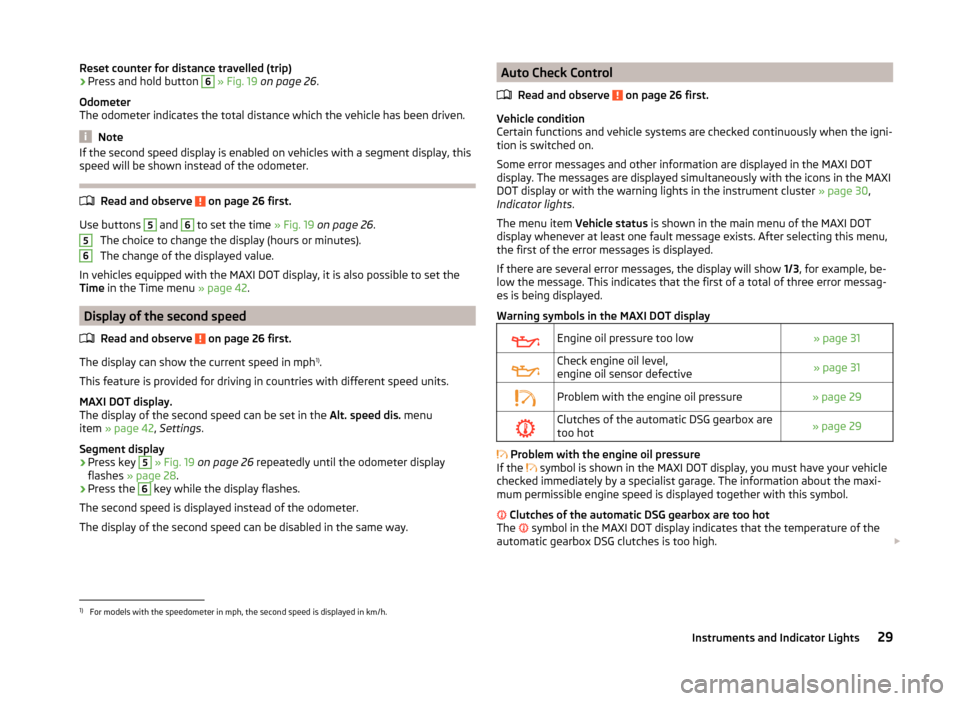
Warning symbols in the MAXI DOT display
Engine oil pressure too low» page 31Check engine oil level,
engine oil sensor defective» page 31Problem with the engine oil pressure» page 29Clutches of the automatic DSG gearbox are
too hot» page 29
Problem with the engine oil pressure
If the symbol is shown in the MAXI DOT display, you must have your vehicle
checked immediately by a specialist garage. The information about the maxi-
mum permissible engine speed is displayed together with this symbol.
Clutches of the automatic DSG gearbox are too hot
The symbol in the MAXI DOT display indicates that the temperature of the
automatic gearbox DSG clutches is too high.
1)
For models with the speedometer in mph, the second speed is displayed in km/h.
29Instruments and Indicator Lights
Page 39 of 193

Information system
Driver information system
Introduction
This chapter contains information on the following subjects:
Using the information system
37
Display a low temperature
38
Gear recommendation
38
Door, boot or engine compartment warning
39
The information system provides the driver with alerts and messages about in-
dividual vehicle systems.
This information and advice is shown in the instrument cluster display or indi-
cated by the illumination of the corresponding indicator light in the instrument
cluster.
The information system provides the following information and instructions
(depending on vehicle equipment).
› Data relating to the multi-function display (MFD)
» page 39.
› Data relating to the Maxi DOT display
» page 42.
› Service interval display
» page 43.
› Auto Check Control
» page 29.
› Selector lever positions for an automatic gearbox
» page 102.
WARNINGConcentrate fully at all times on your driving! As the driver, you are fully re-
sponsible for the operation of your vehicle.Using the information systemFig. 24
Buttons/dial: on the operating lever / on the multifunction steer-
ing wheel
Read and observe
on page 37 first.
Some functions of the information system can be operated using the buttons
on the multifunction steering wheel » Fig. 24.
Description of the operation
Button / wheel
» Fig. 2 4
ActionOperation
ABriefly press at the topor below for a longer timeSelect data / set data valuesPress top
or below for a longer timeDisplay main menu of the
MAXI DOT display » page 42BPress brieflyView information / confirm specificationCPress brieflyTo go up one level in the menu of the
MAXI DOT display » page 42Press and hold buttonDisplay main menu of the
MAXI DOT display » page 42DTurn upwards or down-
wardsSelect data / set data valuesPress brieflyView information / confirm specification37Information system
Page 50 of 193

NoteIndividual settings can be carried out in a specialist workshop.
Locking/unlocking the vehicle from the inside
Fig. 30
Central locking button
Read and observe and on page 45 first.
If the vehicle has not been locked from outside, the » Fig. 30 button can be
used to unlock or lock the vehicle.
Unlocking/locking » Fig. 30
If the icon in the button
is lit, the vehicle is locked.
The central locking system also operates if the ignition is switched off.
The following applies if your vehicle has been locked using the central locking button.
› Opening the doors and the boot lid from the outside is not possible.
› The doors can be unlocked and opened from the inside by a single pull on the
opening lever of the respective door.
› In the event of an accident in which the airbags are deployed, the locked
doors are automatically unlocked in order to enable rescuers to gain access
to the vehicle.
WARNING■ Doors locked from the inside make it difficult for rescuers to get into the
vehicle in an emergency – risk to life!■
If the Safelock system is switched on » page 47, the door opening levers
and the central locking buttons do not operate.
CAUTION
If at least one door has been opened, the vehicle cannot be locked.Child safety lockFig. 31
Back door: left/right
Read and observe
and on page 45 first.
The child safety lock prevents the rear door from being opened from the in-
side. The door can only be opened from the outside.
Switching the cooling system on and off » Fig. 31
Switching on
Switching off
You can switch the child safety lock on and off using the vehicle key.
48Using the system
Page 54 of 193

Note■When driving always use the existing heating, air conditioning and ventila-
tion system for ventilating the interior of the vehicle. If the windows are
opened, dust as well as other dirt can get into the vehicle and in addition the wind noise is more at certain speeds.■
The window lift mechanism is equipped with protection against overheating.
Repeated opening and closing of the window can cause this mechanism to
overheat. If this happens, it will not be possible to operate the window for a
short time. You will be able to operate the window again as soon as the over-
heating protection has cooled down.
Opening/closing the windows
Fig. 35
Buttons on the driver's door/in the rear doors
Read and observe
and on page 51 first.
All windows can be operated from the driver's seat.
Buttons for window levers » Fig. 35
Driver's door
Passenger door
Right rear door
Left rear door
Safety push-button
Opening
›
Lightly press the appropriate button down and hold it until the window has
moved into the desired position. Releasing the button causes the window to
stop immediately.
ABCDSThe driver's window can be completely opened automatically by briefly press-
ing the button as far as the stop. Renewed pressing of the button causes the
window to stop immediately.
Closing›
Pull gently on the top edge of the corresponding button and hold until the
window has moved into the desired position. Releasing the button causes
the window to stop immediately.
Safety push-button
The buttons for power windows in the rear doors can be deactivated by press-
ing the safety switch
S
» Fig. 35 . The buttons for the electrical power win-
dows at the rear doors are activated again by pressing the safety push-button
S
again.
If the buttons for the rear doors are deactivated, the warning light in the
safety switch
S
lights up.
Force limit
Read and observe
and on page 51 first.
The electrical power windows are fitted with a force limiter.
If there is an obstacle, the closing process is stopped and the window goes
down by several centimetres.
If the obstacle prevents the window from being closed during the next 10 sec-
onds, the closing process is interrupted once again and the window goes down
by several centimetres.
If you attempt to close the window again within 10 seconds of the window be-
ing moved down for the second time, even though the obstacle was not yet
been removed, the closing process is only stopped. During this time it is not
possible to automatically close the window. The force limiter is still switched
on.
The force limiter is only switched off if you attempt to close the window again
within the next 10 seconds - the window will now close with full force!
If you wait longer than 10 seconds, the force limiter is switched on again.
52Using the system
Page 68 of 193
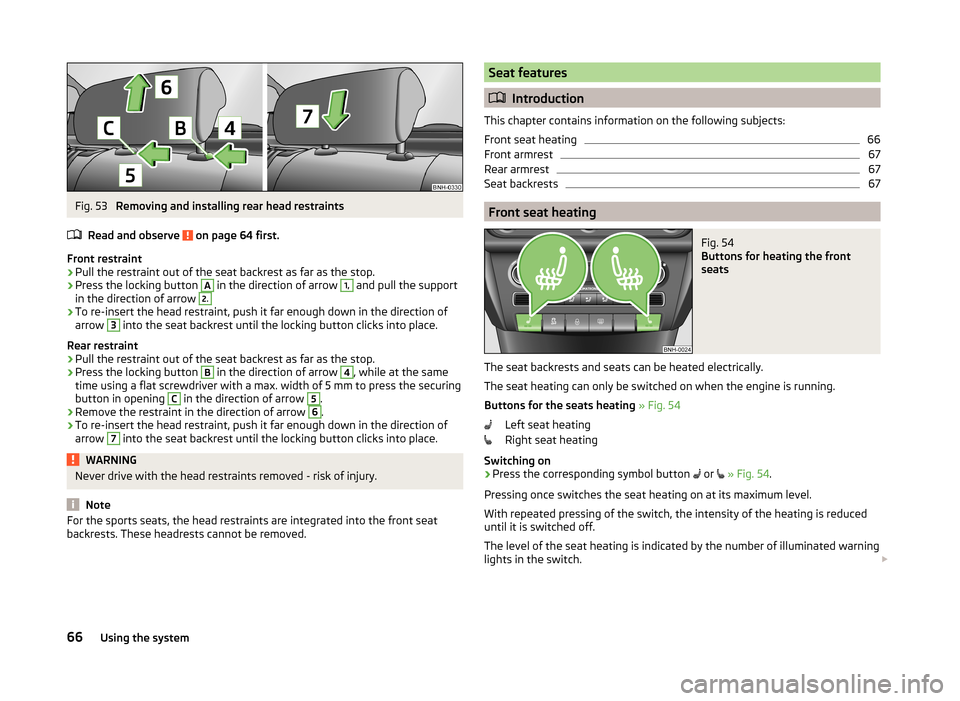
Fig. 53
Removing and installing rear head restraints
Read and observe
on page 64 first.
Front restraint
›
Pull the restraint out of the seat backrest as far as the stop.
›
Press the locking button
A
in the direction of arrow
1,
and pull the support
in the direction of arrow
2.›
To re-insert the head restraint, push it far enough down in the direction of
arrow
3
into the seat backrest until the locking button clicks into place.
Rear restraint
›
Pull the restraint out of the seat backrest as far as the stop.
›
Press the locking button
B
in the direction of arrow
4
, while at the same
time using a flat screwdriver with a max. width of 5 mm to press the securing button in opening
C
in the direction of arrow
5
.
›
Remove the restraint in the direction of arrow
6
.
›
To re-insert the head restraint, push it far enough down in the direction of
arrow
7
into the seat backrest until the locking button clicks into place.
WARNINGNever drive with the head restraints removed - risk of injury.
Note
For the sports seats, the head restraints are integrated into the front seat
backrests. These headrests cannot be removed.Seat features
Introduction
This chapter contains information on the following subjects:
Front seat heating
66
Front armrest
67
Rear armrest
67
Seat backrests
67
Front seat heating
Fig. 54
Buttons for heating the front
seats
The seat backrests and seats can be heated electrically.
The seat heating can only be switched on when the engine is running.
Buttons for the seats heating » Fig. 54
Left seat heating
Right seat heating
Switching on
›
Press the corresponding symbol button or
» Fig. 54 .
Pressing once switches the seat heating on at its maximum level.
With repeated pressing of the switch, the intensity of the heating is reduced
until it is switched off.
The level of the seat heating is indicated by the number of illuminated warning
lights in the switch.
66Using the system
Page 90 of 193

If you select a temperature higher than +29 ℃, “HI” appears in the display.
At both end positions, Climatronic runs at maximum cooling/heating output
and the temperature is automatically not regulated.
Controlling blower
The Climatronic system controls the blower stages automatically in line with the interior temperature. However, the blower level can be manually adjusted
to suit your particular needs.
If the blower speed is reduced to a minimum, Climatronic is switched off.
The blower speed set is indicated by displaying the corresponding number of
segments (pos. 9
» Fig. 93 ) in the display.
Automatic mode
The automatic mode is used in order to maintain a constant temperature and
to demist the windows in the interior of the car.
To switch on press the
button. The display shows
(pos.
4
» Fig. 93 ).
Automatic mode can be switched off by pressing one of the buttons for the air
distribution or by increasing/decreasing the blower speed. The temperature is
nevertheless regulated.
WARNING■ Do not switch off the Climatronic system for longer than necessary.■Switch on the Climatronic system as soon as the windows mist up.
Note
■Do not stick anything on or cover the interior temperature sensor11 » Fig. 93 ; it could have an unfavourable effect on the Climatronic system.■
During operation of the Climatronic, an increase in engine idle speed can oc-
cur under certain circumstances in order to ensure adequate heating comfort.
■
If the windscreen mists up, press the symbol button
. Press the
but-
ton once the windscreen has demisted.
Efficient handling of the cooling system
Read and observe
and on page 84 first.
The air conditioning system compressor uses power from the engine when in
cooling mode, which will affect the fuel consumption.
It recommended to open the windows or the doors of a vehicle for which the
interior has been strongly heated through the effect of direct sunlight in order
to allow the heated air to escape.
The cooling system should not be on if the windows are open.
For the sake of the environment
Pollutant emissions are also reduced when fuel is saved » page 104.
malfunctions
Read and observe
and on page 84 first.
If the cooling system does not operate at outside temperatures higher than +5
°C, there is a problem in the system. The reasons for this may be.
› One of the fuses has blown. Check the fuse and replace if necessa-
ry » page 163 .
› The cooling system has switched off automatically for a short time because
the coolant temperature of the engine is too hot » page 27.
If you are not able to resolve the operational problem yourself, or if the cooler
output has reduced, switch off the cooling system and seek assistance from a
specialist garage.
88Using the system
Page 92 of 193
Internal PhonebookRead and observe
on page 89 first.
An internal phonebook is part of the hands-free system. This phone phone-book can be used depending on the type of mobile phone.
After the first connection of the telephone, the system begins to load the
phone book from the phone and the SIM card into the memory of the control
unit.
Each time the telephone has established a new connection with the hands-
free system, an update of the relevant phone book is performed. The updating
can take a few minutes. During this time the phone book, which was stored af-
ter the last update was completed, is available. Newly stored telephone num-
bers are only shown after the updating has ended.
The update is interrupted if a telephone event (e.g. incoming or outgoing call,
voice control dialogue) occurs during the updating procedure. After the tele-
phone event has ended, the updating starts anew.
The internal phonebook provides 2,500 free memory locations. Each contact
can contain up to 4 numbers.
If the number of contacts loaded exceeds 2,500, the phone book is not com-
plete.
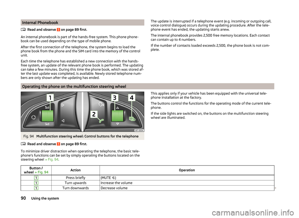
Operating the phone on the multifunction steering wheel
Fig. 94
Multifunction steering wheel: Control buttons for the telephone
Read and observe
on page 89 first.
To minimize driver distraction when operating the telephone, the basic tele-
phone's functions can be set by simply operating the buttons located on the
steering wheel » Fig. 94.
This applies only if your vehicle has been equipped with the universal tele-
phone installation at the factory.
The buttons control the functions for the operating mode of the current tele-
phone.
If the side lights are switched on, the buttons on the multifunction steering wheel are illuminated.Button /
wheel » Fig. 94ActionOperation1Press briefly(MUTE )1Turn upwardsIncrease the volume1Turn downwardsDecrease volume 90Using the system
Page 97 of 193
Music playback via Bluetooth®
The universal telephone pre-installation GSM II makes it possible to play back
music via Bluetooth ®
from the devices such as MP3 player, mobile phone or
notebook.
To ensure that music can be played via Bluetooth ®
, you must first pair the de-
vice with the hands-free system in the Phone - Bluetooth - Media player
menu.The music playback process is performed on the connected device.
The universal telephone pre-installation GSM II ensures that the music played back via the hands-free system can be controlled with the remote con-
trol » page 94 , Voice commands .
Note
The device being connected must support the Bluetooth ®
A2DP profile; refer
to the operating instructions for the relevant device being connected.
Operating the radio and navigation system on the multifunction steering wheel
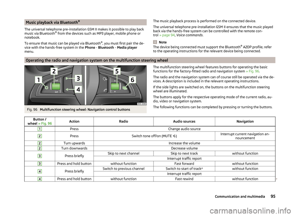
Fig. 96
Multifunction steering wheel: Navigation control buttons
The multifunction steering wheel features buttons for operating the basic
functions for the factory-fitted radio and navigation system » Fig. 96.
The radio and the navigation system can of course still be operated via the de- vices. A description is included in the relevant operating instructions.
If the side lights are switched on, the buttons on the multifunction steering wheel are illuminated.
The buttons apply for the respective operating mode of the current radio, au-
dio, video or navigation system.
The following functions can be completed by pressing or turning the buttons.Button /
wheel » Fig. 96ActionRadioAudio sourcesNavigation1PressChange audio source2PressSwitch tone off/on (MUTE )Interrupt current navigation an-
nouncement2Turn upwardsIncrease the volume2Turn downwardsDecrease volume3Press brieflySkip to next channelSkip to next trackwithout functionInterrupt traffic report3Press and hold buttonwithout functionFast forwardwithout function4Press brieflySwitch to previous channelSwitch to start of track a)without functionInterrupt traffic report4Press and hold buttonwithout functionFast rewindwithout function
95Communication and multimedia
Page 108 of 193
Assist systems
Braking and stabilisation systems
Introduction
This chapter contains information on the following subjects:
Electronic Stability Control (ESC)
106
Anti-lock Braking System (ABS)
106
Traction Control System (TCS)
106
Electronic Differential Lock (EDL)
107
Hydraulic Brake Assist (HBA)
107
Hill Hold Control (HHC)
107
This chapter deals with the functions of the braking and stabilisation systems,
with the error indicator referred to in chapter » page 30, Indicator lights .
The braking and stabilisation systems are automatically activated each time
the ignition is switched on.
WARNING■ A lack of fuel can cause irregular engine running or cause the engine to
shut down. The brake assist systems would then fail to function – risk of
accident!■
The increased safety provided by the brake assist systems must not
tempt you to take safety risks – risk of accident!
■
Adjust the speed and driving style to the current visibility, weather, road
and traffic conditions.
Electronic Stability Control (ESC)
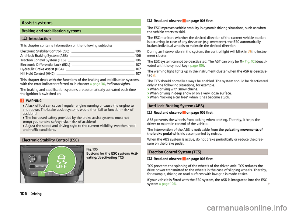
Fig. 105
Buttons for the ESC system: Acti-
vating/deactivating TCS
Read and observe on page 106 first.
The ESC improves vehicle stability in dynamic driving situations, such as when the vehicle starts to skid.
The ESC monitors whether the desired direction of the current vehicle motion
is occurring. In case of any deviation (e.g. oversteer), the ESC automatically
brakes individual wheels to maintain the desired direction.
During an intervention in the system, the control light will blink in
the instru-
ment cluster.
The ESC system cannot be deactivated. The AST can only be
» Fig. 105 deacti-
vated with the symbol key » page 106.
The warning light lights up in the instrument cluster when the ASR is deactiva- ted .
The TCS should normally always be enabled. The system should be deactivated
only in the following situations, for example.
› When driving with snow chains.
› When driving in deep snow or on a very loose surface.
› When “rocking a car free” when it has become stuck.
Anti-lock Braking System (ABS)
Read and observe
on page 106 first.
ABS prevents the wheels from locking when braking. Thereby, it helps the
driver to maintain control of the vehicle.
The intervention of the ABS is noticeable from the pulsating movements of
the brake pedal which is accompanied by noises.
When the ABS system is active, do not brake periodically or reduce the pres-
sure on the brake pedal.
Traction Control System (TCS)
Read and observe
on page 106 first.
TCS prevents the spinning of the wheels of the driven axle. TCS reduces thedrive power transmitted to the wheels in the case of slipping wheels. Thereby,
for example, driving on road surfaces with low grip is made easier.
If your vehicle is fitted with the ESC system, the ASR is integrated into the ESC
system » page 106 .
106Driving