ECU SKODA RAPID SPACEBACK 2014 1.G User Guide
[x] Cancel search | Manufacturer: SKODA, Model Year: 2014, Model line: RAPID SPACEBACK, Model: SKODA RAPID SPACEBACK 2014 1.GPages: 204, PDF Size: 27.11 MB
Page 73 of 204
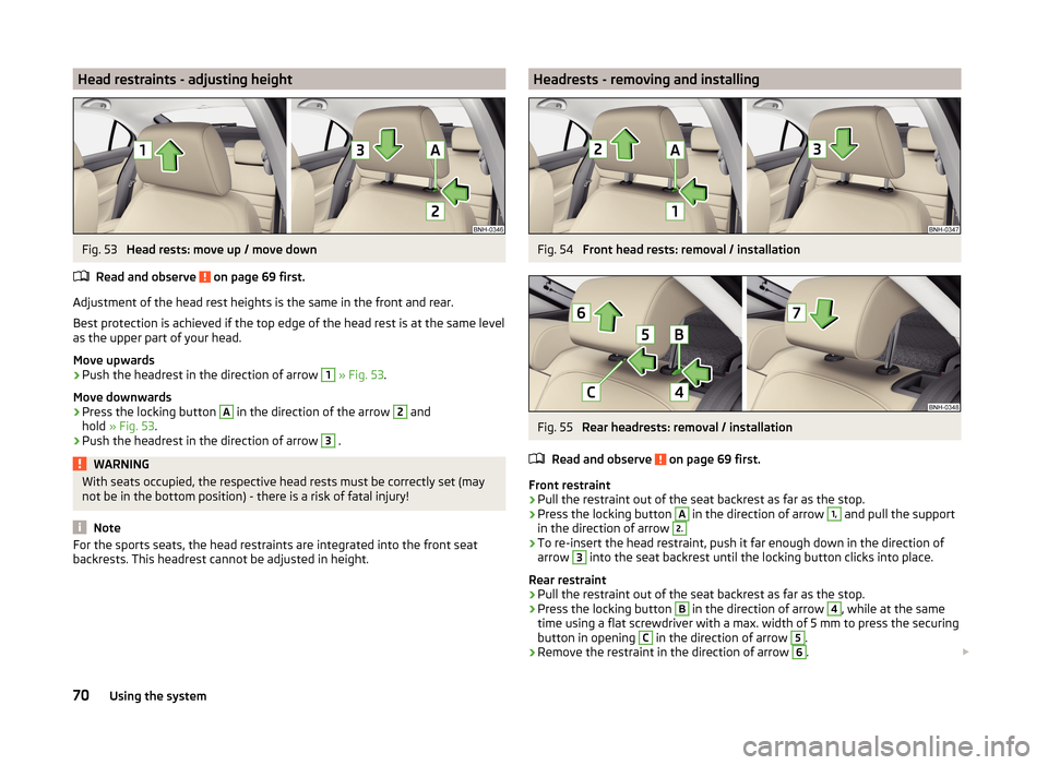
Head restraints - adjusting heightFig. 53
Head rests: move up / move down
Read and observe
on page 69 first.
Adjustment of the head rest heights is the same in the front and rear.
Best protection is achieved if the top edge of the head rest is at the same level as the upper part of your head.
Move upwards
›
Push the headrest in the direction of arrow
1
» Fig. 53 .
Move downwards
›
Press the locking button
A
in the direction of the arrow
2
and
hold » Fig. 53 .
›
Push the headrest in the direction of arrow
3
.
WARNINGWith seats occupied, the respective head rests must be correctly set (may
not be in the bottom position) - there is a risk of fatal injury!
Note
For the sports seats, the head restraints are integrated into the front seat
backrests. This headrest cannot be adjusted in height.Headrests - removing and installingFig. 54
Front head rests: removal / installation
Fig. 55
Rear headrests: removal / installation
Read and observe
on page 69 first.
Front restraint
›
Pull the restraint out of the seat backrest as far as the stop.
›
Press the locking button
A
in the direction of arrow
1,
and pull the support
in the direction of arrow
2.›
To re-insert the head restraint, push it far enough down in the direction of
arrow
3
into the seat backrest until the locking button clicks into place.
Rear restraint
›
Pull the restraint out of the seat backrest as far as the stop.
›
Press the locking button
B
in the direction of arrow
4
, while at the same
time using a flat screwdriver with a max. width of 5 mm to press the securing button in opening
C
in the direction of arrow
5
.
›
Remove the restraint in the direction of arrow
6
.
70Using the system
Page 74 of 204
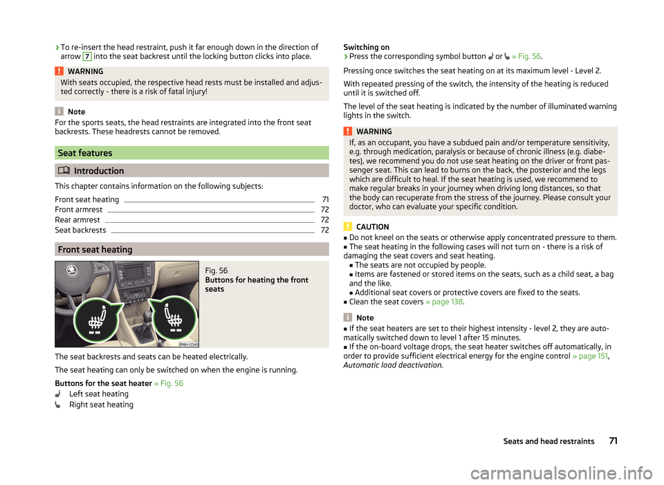
›To re-insert the head restraint, push it far enough down in the direction of
arrow 7 into the seat backrest until the locking button clicks into place.WARNINGWith seats occupied, the respective head rests must be installed and adjus- ted correctly - there is a risk of fatal injury!
Note
For the sports seats, the head restraints are integrated into the front seat
backrests. These headrests cannot be removed.
Seat features
Introduction
This chapter contains information on the following subjects:
Front seat heating
71
Front armrest
72
Rear armrest
72
Seat backrests
72
Front seat heating
Fig. 56
Buttons for heating the front
seats
The seat backrests and seats can be heated electrically.
The seat heating can only be switched on when the engine is running.
Buttons for the seat heater » Fig. 56
Left seat heating
Right seat heating
Switching on›Press the corresponding symbol button or » Fig. 56 .
Pressing once switches the seat heating on at its maximum level - Level 2.
With repeated pressing of the switch, the intensity of the heating is reduced
until it is switched off.
The level of the seat heating is indicated by the number of illuminated warning
lights in the switch.WARNINGIf, as an occupant, you have a subdued pain and/or temperature sensitivity,
e.g. through medication, paralysis or because of chronic illness (e.g. diabe-
tes), we recommend you do not use seat heating on the driver or front pas-
senger seat. This can lead to burns on the back, the posterior and the legs
which are difficult to heal. If the seat heating is used, we recommend to
make regular breaks in your journey when driving long distances, so that
the body can recuperate from the stress of the journey. Please consult your
doctor, who can evaluate your specific condition.
CAUTION
■ Do not kneel on the seats or otherwise apply concentrated pressure to them.■The seat heating in the following cases will not turn on - there is a risk of
damaging the seat covers and seat heating. ■The seats are not occupied by people.
■ Items are fastened or stored items on the seats, such as a child seat, a bag
and the like.
■ Additional seat covers or protective covers are fixed to the seats.■
Clean the seat covers » page 138.
Note
■
If the seat heaters are set to their highest intensity - level 2, they are auto-
matically switched down to level 1 after 15 minutes.■
If the on-board voltage drops, the seat heater switches off automatically, in
order to provide sufficient electrical energy for the engine control » page 151,
Automatic load deactivation .
71Seats and head restraints
Page 76 of 204
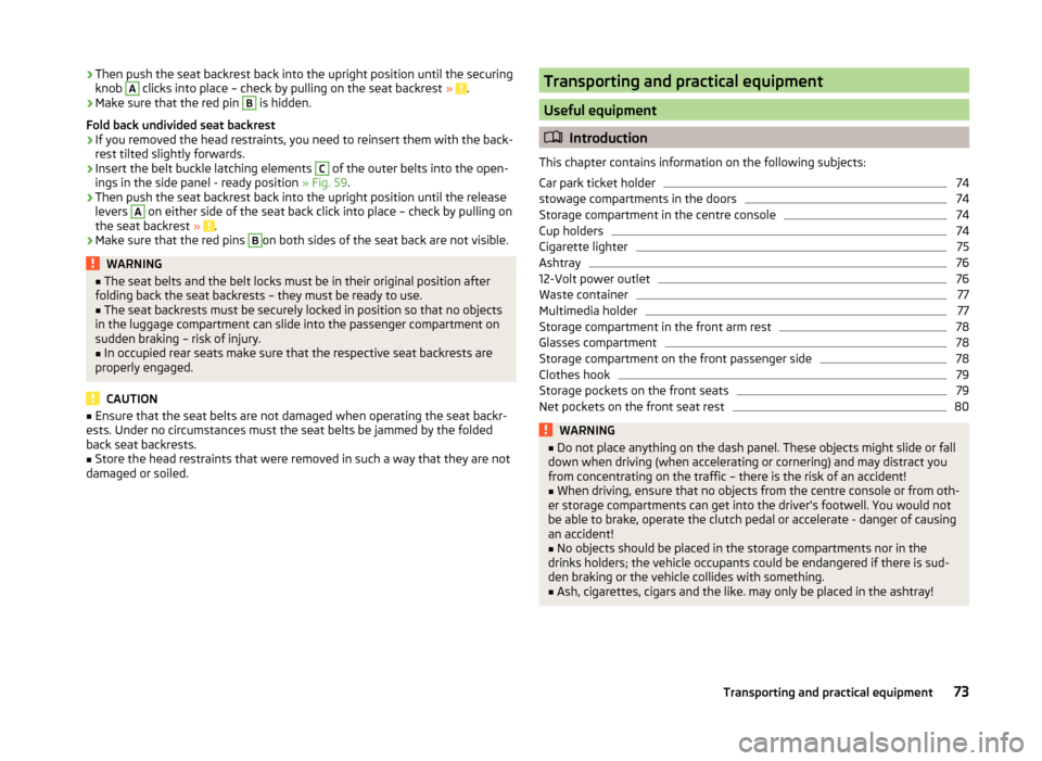
›Then push the seat backrest back into the upright position until the securing
knob A clicks into place – check by pulling on the seat backrest » .›
Make sure that the red pin
B
is hidden.
Fold back undivided seat backrest
›
If you removed the head restraints, you need to reinsert them with the back-
rest tilted slightly forwards.
›
Insert the belt buckle latching elements
C
of the outer belts into the open-
ings in the side panel - ready position » Fig. 59.
›
Then push the seat backrest back into the upright position until the release
levers
A
on either side of the seat back click into place – check by pulling on
the seat backrest » .
›
Make sure that the red pins
B
on both sides of the seat back are not visible.
WARNING■
The seat belts and the belt locks must be in their original position after
folding back the seat backrests – they must be ready to use.■
The seat backrests must be securely locked in position so that no objects
in the luggage compartment can slide into the passenger compartment on
sudden braking – risk of injury.
■
In occupied rear seats make sure that the respective seat backrests are
properly engaged.
CAUTION
■ Ensure that the seat belts are not damaged when operating the seat backr-
ests. Under no circumstances must the seat belts be jammed by the folded
back seat backrests.■
Store the head restraints that were removed in such a way that they are not
damaged or soiled.
Transporting and practical equipment
Useful equipment
Introduction
This chapter contains information on the following subjects:
Car park ticket holder
74
stowage compartments in the doors
74
Storage compartment in the centre console
74
Cup holders
74
Cigarette lighter
75
Ashtray
76
12-Volt power outlet
76
Waste container
77
Multimedia holder
77
Storage compartment in the front arm rest
78
Glasses compartment
78
Storage compartment on the front passenger side
78
Clothes hook
79
Storage pockets on the front seats
79
Net pockets on the front seat rest
80WARNING■ Do not place anything on the dash panel. These objects might slide or fall
down when driving (when accelerating or cornering) and may distract you
from concentrating on the traffic – there is the risk of an accident!■
When driving, ensure that no objects from the centre console or from oth-
er storage compartments can get into the driver's footwell. You would not
be able to brake, operate the clutch pedal or accelerate - danger of causing
an accident!
■
No objects should be placed in the storage compartments nor in the
drinks holders; the vehicle occupants could be endangered if there is sud-
den braking or the vehicle collides with something.
■
Ash, cigarettes, cigars and the like. may only be placed in the ashtray!
73Transporting and practical equipment
Page 83 of 204
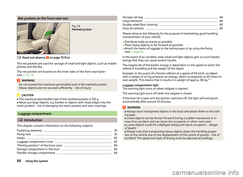
Net pockets on the front seat restFig. 74
Meshed pocket
Read and observe on page 73 first.
The net pockets are used for storage of small and light objects, such as mobile
phones and the like.
The net pockets are located on the inner sides of the front seat backr-
ests » Fig. 74 .
WARNINGDo not exceed the maximum permissible load of the meshed pockets.
Heavy objects are not secured sufficiently – risk of injury!
CAUTION
■ The maximum permissible load of the meshed pockets is 150 g.■Never put large objects, e.g. bottles or objects with sharp edges into the
mesh pockets - risk of damaging the mesh pockets and seat coverings.
Luggage compartment
Introduction
This chapter contains information on the following subjects:
Fastening elements
81
Fixing nets
81
Hooks
82
Luggage compartment cover
82
“Parking position” of the boot cover
83
Storage compartment in the boot
83
Flexible storage compartment
84Storage net bag84Cargo elements84
Double-sided floor covering
85
Class N1 vehicles
85
Please observe the following for the purpose of maintaining good handling
characteristics of your vehicle:
›
Distribute loads as evenly as possible.
›
Place heavy objects as far forward as possible.
›
Attach the items of luggage to the lashing eyes or by using the fixing
nets » page 81 .
In the event of an accident, even small and light objects gain so much kinetic
energy that they can cause severe injuries.
The magnitude of the kinetic energy is dependent on the speed at which the
vehicle is travelling and the weight of the object.
Example: In the event of a frontal collision at a speed of 50 km/h, an object
with a weight of 4.5 kg produces an energy, which corresponds to 20 times its
own weight. This means that it results in a weight of approx. 90 kg “ ”.
Luggage compartment light
The warning light turns on when tailgate is opened.
The warning light turns off when the tailgate is closed.
If the boot lid is open and the ignition switched off, the light will extinguish
automatically after around 10 minutes.
WARNING■ Always store transported objects in the boot and attach them to the lash-
ing eyes.■
Loose objects can be thrown forward during a sudden manoeuvre or in
case of an accident and can injure the occupants or other road users.
■
Loose objects could hit a deployed airbag and injure occupants – danger
of death!
■
Please note that transporting heavy objects alters the handling proper-
ties of the vehicle due to the displacement of the centre of gravity – risk of
accident! The speed and style of driving must be adjusted accordingly.
80Using the system
Page 85 of 204

Fig. 77
Fastening vertical pocket
Read and observe and on page 80 first.
Fastening examples for nets » Fig. 76
Horizontal pocket
Floor net
Vertical pocket
WARNINGDo not exceed the maximum permissible load of the fixing nets. Heavy ob-
jects are not secured sufficiently – risk of injury!
CAUTION
■ The maximum permissible load of the fixing nets is 1.5 kg.■Do not place any sharp objects in the nets – risk of net damage.
Hooks
Fig. 78
Hooks
Read and observe and on page 80 first.
The hook is used to affix small items of luggage such as bags.
The hooks are located on both sides of the luggage compartment » Fig. 78.
ABCCAUTIONThe maximum permissible load of the hook is 7.5 kg.
Luggage compartment cover
Fig. 79
Removing the boot cover
Read and observe
and on page 80 first.
The boot cover can be removed if you want to transport bulky goods.
Removing
›
Unhook the retaining straps
A
from the flap in the direction of arrow
1
» Fig. 79 .
›
Hold the cover in the upper position and press the bottom of the cover in the
area of the pin
C
.
›
Remove the cover in the direction of the arrow
2
.
The dismantled luggage compartment cover can be stowed away behind the
rear seat backrest in the so called “parking position” » page 83.
Installing
›
Place the cover on the contact surfaces of the side trim panel.
›
Position the mounts on the cover
B
onto the side trim panel via pins
C
» Fig. 79 .
›
Press on the upper side of the cover so that the mounts fully interlock into
the pins.
›
Insert the retaining bands
A
opposite to the direction of arrow
1
on the
boot lid.
82Using the system
Page 87 of 204

CAUTION■The storage compartments are designed for storing small objects of up to
1.5 kg. in weight in total.■
When using the storage compartment, take care not to damage it or the lug-
gage compartment lining.
Flexible storage compartment
Fig. 82
Flexible storage compartment
Read and observe and on page 80 first.
The flexible storage compartment can be installed on the right-hand side of the boot » Fig. 82.
Installing
›
Place both ends of the storage compartment into the openings on the right
side panel of the luggage compartment.
›
Push the storage compartment down to lock it.
Removing
›
Grasp the storage compartment on the two upper corners.
›
Remove the storage compartment by pulling upwards and then towards you.
CAUTION
The storage compartment is designed for storing small objects with a maxi-
mum total weight of 8 kg.
Note
The flexible storage compartment cannot be installed on vehicles with the var-
iable loading floor » page 85.Storage net bagFig. 83
Meshed pocket for storage
Read and observe and on page 80 first.
The meshed pocket for storage is located on the right-hand side of the
boot » Fig. 83 .
CAUTION
The meshed pocket for storage is designed for storing small objects of up to
1.5 kg. in weight in total.
Cargo elements
Fig. 84
Removing cargo elements / example on how to mount the load by
means of the cargo element
Read and observe
and on page 80 first.
The Cargo elements can be used for mounting and securing of the load from
slipping in the boot.
The Cargo elements can be stored under the floor in the boot.
84Using the system
Page 88 of 204

Secure load›Remove the cargo elements in direction of arrow » Fig. 84 - .›
Secure the cargo element with Velcro on the floor covering of the luggage
compartment » Fig. 84 -
.
CAUTION
The cargo elements are designed for attaching loads with a maximum gross
weight of 8 kg.
Double-sided floor covering
Read and observe
and on page 80 first.
You can fit a double-sided floor covering in the luggage compartment.
One side of the double-sided floor covering is made of fabric, the other side is
washable (easy to maintain).
The washable side is used to transport wet or dirty items.
Note
For easier turning of the covering, use the loop attached.
Class N1 vehicles
Read and observe
and on page 80 first.
In class N1 vehicles that are not fitted with a protective grille, a lashing set that
complies with the EN 12195 standard (1 - 4) must be used for fastening the
load.
Proper functioning of the electrical installation is essential for safe vehicle op-
eration. It is important to ensure that the electrical installation is not damaged
during the adjustment process or when the storage area is being loaded and
unloaded.
Variable loading floor in the luggage compartment (Estate)
Introduction
This chapter contains information on the following subjects:
Setting in the upper position
85
Setting in the lower position
86
Removing/inserting
86Folding up/down87“Parking position”87
The variable loading floor can be set to the upper or lower position.
For easier handling of the spare tire, for example, the variable loading floor can be set to two positions » page 87, Folding up/down and » page 87 , “Park-
ing position” .
CAUTION
The maximum permissible load of the variable loading floor is 75 kg. For the
transport of heavy loads, adjust the variable loading floor to the lower position
or remove it from the vehicle.
Setting in the upper position
Fig. 85
Set the variable loading floor to the upper position
Read and observe
on page 85 first.
The variable loading floor in the lower position can be set to the upper position as follows.
›
Grasp the variable loading floor at handle
A
» Fig. 85 .
85Transporting and practical equipment
Page 91 of 204
Roof rack
Introduction
This chapter contains information on the following subjects:
fixing points for base support
88
Roof load
88WARNING■ The transported items on the roof rack must be securely attached – risk
of accident!■
Always secure the load with appropriate and undamaged lashing straps
or tensioning straps.
■
Distribute the load evenly over the roof rack system.
■
When transporting heavy objects or objects which take up a large area on
the roof rack system, handling of the car may change as a result of the dis-
placement of the centre of gravity. The style of driving and speed must
therefore be adapted to the current circumstances.
■
Avoid abrupt and sudden driving/braking manoeuvres.
■
The permissible roof load, permissible axle loads and permissible total ve-
hicle weight must not be exceeded under any circumstance – risk of acci-
dent!
CAUTION
■ Only roof racks from the ŠKODA Original Accessories range should be used.■When dealing with roof rack systems, the installation instructions supplied
with the roof luggage rack system must be observed.■
On models fitted with a power sliding/tilting roof, ensure that the extended
sliding/tilting roof does not hit any items of luggage transported on the roof.
■
Ensure that the boot lid does not hit the roof load when opened.
■
The height of the vehicle changes after mounting a roof luggage rack system
and the load that is secured to it. Compare the vehicle height with available
clearances, such as underpasses and garage doors.
■
Always remove the roof luggage rack system before entering an automated
car wash.
■
Ensure the roof aerial is not impaired by the secured load.
For the sake of the environment
The increased aerodynamic drag results in a higher fuel consumption.fixing points for base supportFig. 90
Attachment points
Read and observe
and on page 88 first.
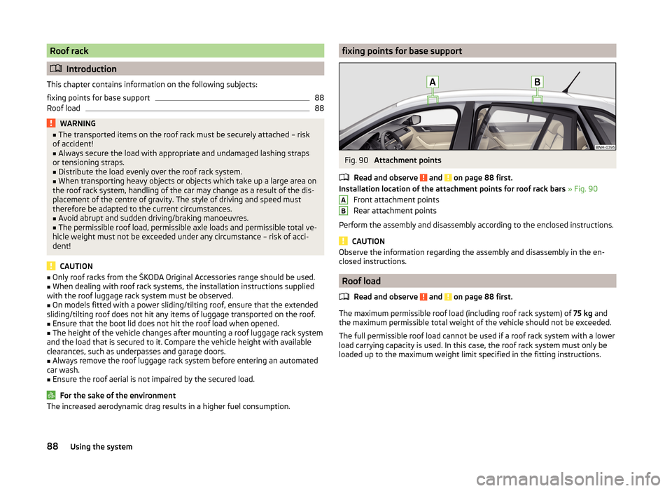
Installation location of the attachment points for roof rack bars » Fig. 90
Front attachment points
Rear attachment points
Perform the assembly and disassembly according to the enclosed instructions.
CAUTION
Observe the information regarding the assembly and disassembly in the en-
closed instructions.
Roof load
Read and observe
and on page 88 first.
The maximum permissible roof load (including roof rack system) of 75 kg and
the maximum permissible total weight of the vehicle should not be exceeded.
The full permissible roof load cannot be used if a roof rack system with a lower
load carrying capacity is used. In this case, the roof rack system must only be
loaded up to the maximum weight limit specified in the fitting instructions.
AB88Using the system
Page 106 of 204

This website contains information about the vehicle, the Wi-Fi connection and
SmartGate.
In the Configuration area the Wi-Fi connection settings can be adjusted.
Save the setting changes
The setting changes are only applied after performing the following steps.
› The changes are saved by pressing the “Save” button.
› SmartGate is restarted by pressing the “Reboot ”button.
Password Management
Read and observe
on page 102 first.
Password management can be done in the connected device on the Smart-
Gate website » page 102, Smart Gate website .
The changes are applied after saving and restarting SmartGate » page 103,
Save the setting changes .
Change password
›
Enter a new password in the Configuration area in menu option WPA / WPA2 key.
The password must be 8-17 characters without diacritics or special characters
(for example, -, /, etc.).
Connection option without entering a password
›
In the Configuration area set the value Open in the menu item Security .
Forgot password
If you have forgotten your password, SmartGate must be reset to factory set-
tings in a specialized workshop.
103Communication and multimedia
Page 110 of 204
Low brake fluid level
An insufficient level of brake fluid may result in problems in the brake system.
The level of the brake fluid is monitored electronically » page 35,
Brake sys-
tem .
Brake booster
The brake booster increases the pressure generated with the brake pedal. The
brake booster only operates when the engine is running.WARNINGOnly apply the brakes for the purpose of drying and cleaning the brake
discs if the traffic conditions permit this. Do not place any other road users
in jeopardy.
Handbrake
Fig. 100
Handbrake
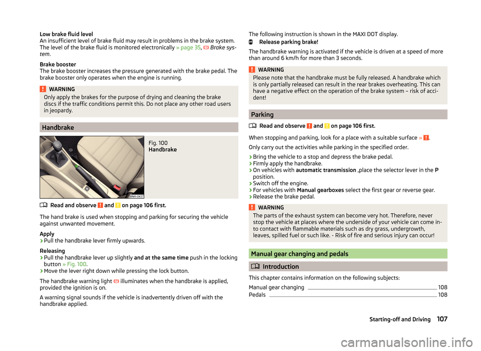
Read and observe and on page 106 first.
The hand brake is used when stopping and parking for securing the vehicle
against unwanted movement.
Apply
›
Pull the handbrake lever firmly upwards.
Releasing
›
Pull the handbrake lever up slightly and at the same time push in the locking
button » Fig. 100 .
›
Move the lever right down while pressing the lock button.
The handbrake warning light
illuminates when the handbrake is applied,
provided the ignition is on.
A warning signal sounds if the vehicle is inadvertently driven off with the
handbrake applied.
The following instruction is shown in the MAXI DOT display.
Release parking brake!
The handbrake warning is activated if the vehicle is driven at a speed of more
than around 6 km/h for more than 3 seconds.WARNINGPlease note that the handbrake must be fully released. A handbrake which
is only partially released can result in the rear brakes overheating. This can
have a negative effect on the operation of the brake system – risk of acci-
dent!
Parking
Read and observe
and on page 106 first.
When stopping and parking, look for a place with a suitable surface » .
Only carry out the activities while parking in the specified order.
›
Bring the vehicle to a stop and depress the brake pedal.
›
Firmly apply the handbrake.
›
On vehicles with automatic transmission ,place the selector lever in the P
position.
›
Switch off the engine.
›
For vehicles with Manual gearboxes select the first gear or reverse gear.
›
Release the brake pedal.
WARNINGThe parts of the exhaust system can become very hot. Therefore, never
stop the vehicle at places where the underside of your vehicle can come in-
to contact with flammable materials such as dry grass, undergrowth,
leaves, spilled fuel or such like. - Risk of fire and serious injury can occur!
Manual gear changing and pedals
Introduction
This chapter contains information on the following subjects:
Manual gear changing
108
Pedals
108107Starting-off and Driving