engine SKODA RAPID SPACEBACK 2014 1.G Owner's Guide
[x] Cancel search | Manufacturer: SKODA, Model Year: 2014, Model line: RAPID SPACEBACK, Model: SKODA RAPID SPACEBACK 2014 1.GPages: 204, PDF Size: 27.11 MB
Page 68 of 204
Note■If the on-board voltage drops, the heater switches off automatically, in order
to provide sufficient electrical energy for the engine control » page 151, Auto-
matic load deactivation .■
If the light is flashing inside the button the heater is off due to low battery.
Front sun visors
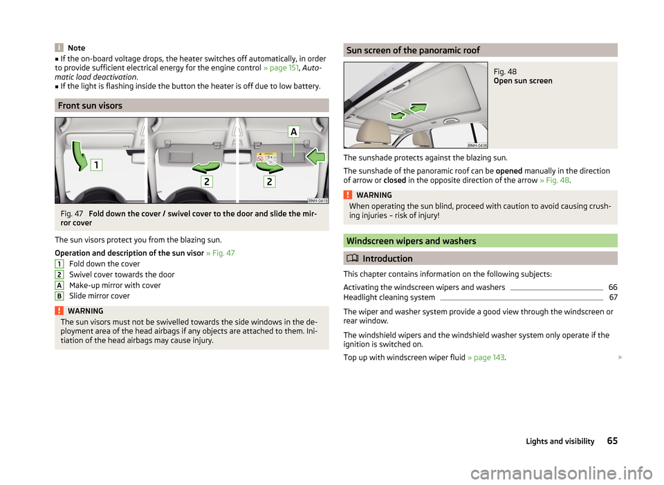
Fig. 47
Fold down the cover / swivel cover to the door and slide the mir-
ror cover
The sun visors protect you from the blazing sun.
Operation and description of the sun visor » Fig. 47
Fold down the cover
Swivel cover towards the door
Make-up mirror with cover
Slide mirror cover
WARNINGThe sun visors must not be swivelled towards the side windows in the de-
ployment area of the head airbags if any objects are attached to them. Ini-
tiation of the head airbags may cause injury.12ABSun screen of the panoramic roofFig. 48
Open sun screen
The sunshade protects against the blazing sun.
The sunshade of the panoramic roof can be opened manually in the direction
of arrow or closed in the opposite direction of the arrow » Fig. 48.
WARNINGWhen operating the sun blind, proceed with caution to avoid causing crush-
ing injuries – risk of injury!
Windscreen wipers and washers
Introduction
This chapter contains information on the following subjects:
Activating the windscreen wipers and washers
66
Headlight cleaning system
67
The wiper and washer system provide a good view through the windscreen or
rear window.
The windshield wipers and the windshield washer system only operate if the
ignition is switched on.
Top up with windscreen wiper fluid » page 143.
65Lights and visibility
Page 71 of 204
Do not attach external navigation devices on to the windscreen or in the vicini-
ty of the automatic dimming interior mirror » .WARNINGThe illuminated display of an external navigation unit can lead to opera-
tional faults to the automatic dimming interior mirror – risk of accident.WARNINGThe mirrors with automatic dimming contain an electrolyte liquid which can
escape if mirror glass is broken.■
The leaking electrolytic fluid can irritate the skin, eyes and breath appara-
tus. Immediately seek out fresh air and leave the vehicle. If this is not pos-
sible, at least open the window.
■
If you swallow electrolytic fluid, seek medical assistance immediately.
■
If your eyes or skin come into contact with the electrolytic fluid, immedi-
ately wash the affected area for a few minutes long with a lot of water.
Then consult a doctor immediately.
CAUTION
Automatic mirror dimming operates only properly if the light striking the sen-
sors is not affected by other objects.
Exterior mirror
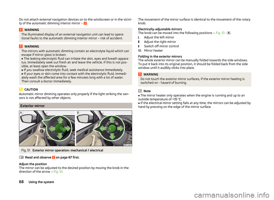
Fig. 51
Exterior mirror operation: mechanical / electrical
Read and observe
on page 67 first.
Adjust the position
The mirror can be adjusted to the desired position by moving the knob in the
direction of the arrow » Fig. 51.
The movement of the mirror surface is identical to the movement of the rotary
knob.
Electrically-adjustable mirrors
The knob can be moved into the following positions » Fig. 51 -
.
Adjust the left mirror
Adjust the right mirror
Switch off mirror control
Mirror heater
Folding in the exterior mirrors
The whole exterior mirror can be manually folded towards the side windows.
To put it back into its original position, it should be folded back from the side
window until it audibly clicks into place.WARNINGDo not touch the exterior mirror surfaces, if the exterior mirror heating is
switched on - hazard of burning.
Note
■ The mirror heater only operates when the engine is running and up to an
outside temperature of +35 ℃.■
If the electrical mirror setting fails at any time, the mirrors can be adjusted by
hand by pressing on the edge of the mirror surface.
68Using the system
Page 74 of 204
›To re-insert the head restraint, push it far enough down in the direction of
arrow 7 into the seat backrest until the locking button clicks into place.WARNINGWith seats occupied, the respective head rests must be installed and adjus- ted correctly - there is a risk of fatal injury!
Note
For the sports seats, the head restraints are integrated into the front seat
backrests. These headrests cannot be removed.
Seat features
Introduction
This chapter contains information on the following subjects:
Front seat heating
71
Front armrest
72
Rear armrest
72
Seat backrests
72
Front seat heating
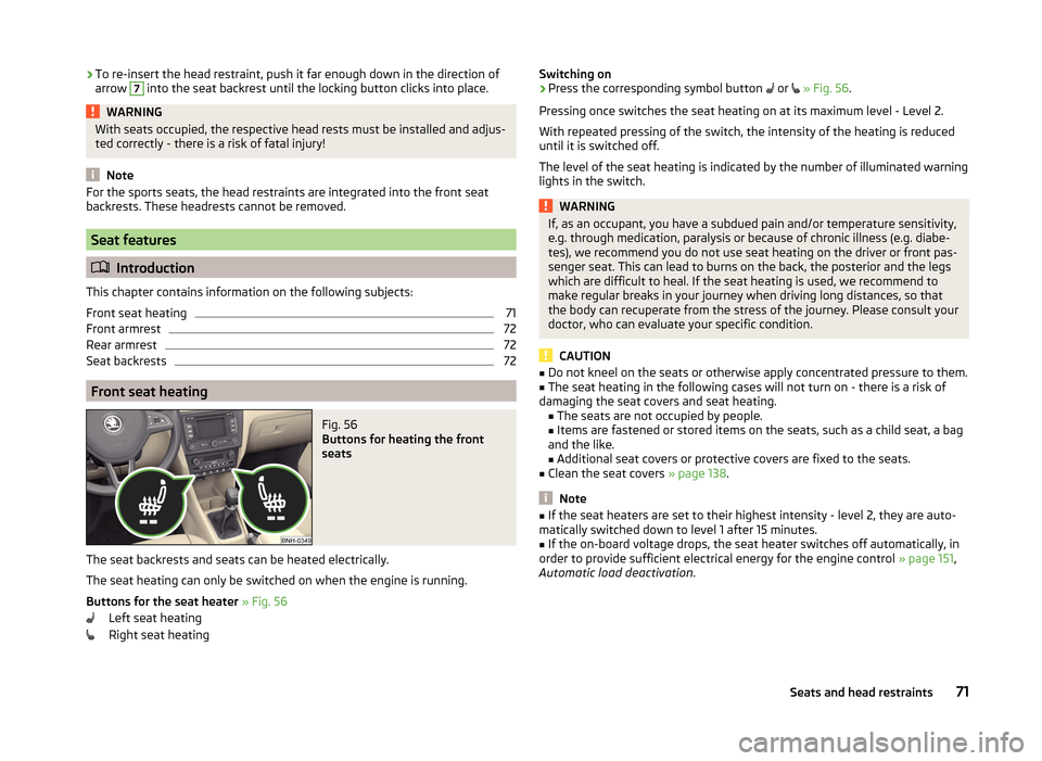
Fig. 56
Buttons for heating the front
seats
The seat backrests and seats can be heated electrically.
The seat heating can only be switched on when the engine is running.
Buttons for the seat heater » Fig. 56
Left seat heating
Right seat heating
Switching on›Press the corresponding symbol button or » Fig. 56 .
Pressing once switches the seat heating on at its maximum level - Level 2.
With repeated pressing of the switch, the intensity of the heating is reduced
until it is switched off.
The level of the seat heating is indicated by the number of illuminated warning
lights in the switch.WARNINGIf, as an occupant, you have a subdued pain and/or temperature sensitivity,
e.g. through medication, paralysis or because of chronic illness (e.g. diabe-
tes), we recommend you do not use seat heating on the driver or front pas-
senger seat. This can lead to burns on the back, the posterior and the legs
which are difficult to heal. If the seat heating is used, we recommend to
make regular breaks in your journey when driving long distances, so that
the body can recuperate from the stress of the journey. Please consult your
doctor, who can evaluate your specific condition.
CAUTION
■ Do not kneel on the seats or otherwise apply concentrated pressure to them.■The seat heating in the following cases will not turn on - there is a risk of
damaging the seat covers and seat heating. ■The seats are not occupied by people.
■ Items are fastened or stored items on the seats, such as a child seat, a bag
and the like.
■ Additional seat covers or protective covers are fixed to the seats.■
Clean the seat covers » page 138.
Note
■
If the seat heaters are set to their highest intensity - level 2, they are auto-
matically switched down to level 1 after 15 minutes.■
If the on-board voltage drops, the seat heater switches off automatically, in
order to provide sufficient electrical energy for the engine control » page 151,
Automatic load deactivation .
71Seats and head restraints
Page 79 of 204

AshtrayFig. 66
Remove front / rear ashtray
Read and observe
on page 73 first.
The ashtray can be used for discarding ash, cigarettes, cigars and the like » .
Removing
›
Pull out the ashtray in the direction of the arrow » Fig. 66.
Fitting
›
Push-in the ashtray against the direction of the arrow » Fig. 66.
WARNINGNever place flammable objects in the ashtray – risk of fire!
CAUTION
When removing, do not hold the ashtray at the cover – risk of breakage.
12-Volt power outlet
Fig. 67
12-Volt power socket
Read and observe on page 73 first.
Use
›
Remove the socket cover or the cigarette lighter » Fig. 67.
›
Connect the plug for the electrical appliance to the socket.
The socket also operates if the ignition is switched off . »
WARNING■
Improper use of the power sockets and the electrical accessories can
cause fires, burns and other serious injuries. Therefore, when leaving the
vehicle, never leave people who are not completely independent, such as
children, unattended in the vehicle.■
If the connected electric device becomes too hot, switch it off and discon-
nect it from the power supply immediately.
CAUTION
■ The power socket can only be used for connecting approved electrical acces-
sories with a total power uptake of up to 120 watt.■
Never exceed the maximum power consumption, otherwise the vehicle's
electrical system can be damaged.
■
Connecting appliances when the engine is not running will drain the battery
of the vehicle!
■
Only use matching plugs to avoid damaging the power socket.
■
Only use accessories that have been tested for electromagnetic compatibility
in accordance with the applicable directives.
■
Switch off the devices connected to the power sockets before you switch
the ignition on or off and before starting the engine, to avoid damage from
voltage fluctuations.
■
Observe the operating instructions for the connected devices!
76Using the system
Page 92 of 204
Heating and air conditioning
Heating, ventilation, cooling
Introduction
This chapter contains information on the following subjects:
Air outlet vents
90
Air distribution control
90
Heating
91
Air conditioning (manual air conditioning)
91
Climatronic (automatic air conditioning)
92
Efficient handling of the cooling system
93
malfunctions
93
The heating and air conditioning ventilate and heat the vehicle interior. The air
conditioning system also cools and dehumidifies the vehicle interior.
The heating effect is dependent upon the coolant temperature, thus full heat
output only occurs when the engine has reached its operating temperature.
The cooling system only operates if the following conditions are met. The cooling system is switched on.
The engine is running.
The outside temperature is above approx. +2 °C.
The blower is switched on.
If the cooling system is switched on, the temperature and air humidity drops in
the vehicle. The cooling system prevents the windows from misting up during
winter months.
It is possible to briefly activate re-circulated air mode to enhance the cooling
effect » page 90 .
WARNING■
For your own safety and that of other road users, ensure that all the win-
dows are free of ice, snow and misting.■
The blower should always be on to prevent the windows from misting up.
WARNING (Continued)■ Under certain circumstances, air at a temperature of about 5 °C can flow
out of the vents when the cooling system is switched on.■
To reduce health risks (e.g. common colds), the following instructions for
the use of the cooling system are to be observed. ■The difference between the indoor temperature and the outdoor air
temperature should not be greater than about 5 ° C.
■ The cooling system is to be turned off about 10 minutes before the end
of the journey.
■ Once a year, a disinfection of the air conditioner or the Climatronic is to
be carried out by a specialist company.
CAUTION
■ The air inlet in front of the windscreen must be free from ice, snow or leaves,
for example, to ensure that the heating and cooling system works properly.■
After switching on the cooling Condensation from the evaporator of the air
conditioning may drip down and form a puddle below the vehicle. This is not a
leak!
■
If the coolant temperature is too high, the cooling system is switched off to
ensure that the engine cools down.
Note
The used air streams out through the vents in the luggage compartment.89Heating and air conditioning
Page 95 of 204
Setting the direction of the air outlet » page 90
›
Air flow to the windows
›
Air flow to the upper body
›
Air flow in the footwell
›
Airflow over the windows and into the footwell
Switch recirculation on/off » page 90
Switch the cooling system on/off
Note
■ The warning light in the button illuminates after activation, even if not all
of the conditions for the function of the cooling system have been met. By
lighting up of the warning light in the button, the operational readiness of the
cooling system is signalled.■
During operation of the air conditioning, an increase in engine idle speed may
occur under certain circumstances in order to ensure sufficient heating com-
fort.
Climatronic (automatic air conditioning)
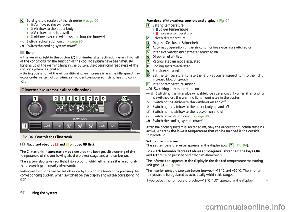
Fig. 94
Controls the Climatronic
Read and observe
and on page 89 first.
The Climatronic in automatic mode ensures the best-possible setting of the
temperature of the outflowing air, the blower stage and air distribution.
The system also takes sunlight into account, which eliminates the need to al-
ter the settings manually afterwards.
Individual functions can be set off or on by turning the knob or by pressing the
corresponding button. When switched on the display shows the corresponding
icon.
CFunctions of the various controls and display » Fig. 94
Setting temperature ›
Lower temperature
›
Increase temperature
Selected temperature
Degrees Celsius or Fahrenheit
Automatic operation of the air conditioning system is switched on
Intensive windshield defroster switched on
Direction of air flow
Recirculated air mode activated
Cooling system activated
Set blower speed
Set the temperature (turn to the left: Reduce fan speed, turn to the right:
Increase blower speed)
Interior temperature sensor Switching automatic mode on Switching the intensive windshield defroster on/off - when this function
is switched on, the warning light illuminates in the button
Switching the airflow to the windows on and off
Switching the airflow to the upper body on and off
Switching the airflow to the footwell on and off
Switch recirculation on/off » page 90
Switch the cooling system on/off
After the cooling system is switched off, only the ventilation function remains
active, whereby the lowest temperature that can be reached is the outside
temperature.
Setting temperature
The set temperature value appears in the display (pos. 2
» Fig. 94 ).
To switch between degrees Celsius and degrees Fahrenheit , the keys
and are to be pressed and held simultaneously.
The information appears in the display in the desired temperature measuring
unit (pos.
3
» Fig. 94 ).
The interior temperature can be set between +18 °C and +29 ℃. The interior
temperature is regulated automatically within this range.
If you select the temperature below +18 ℃, “LO” appears in the display.
123456789101192Using the system
Page 96 of 204
If you select a temperature higher than +29 ℃, “HI” appears in the display.
At both end positions, Climatronic runs at maximum cooling/heating output
and the temperature is automatically not regulated.
Controlling blower
The Climatronic system controls the blower stages automatically in line with the interior temperature. However, the blower level can be manually adjusted
to suit your particular needs.
If the blower speed is reduced to a minimum, Climatronic is switched off.
The blower speed set is indicated by displaying the corresponding number of
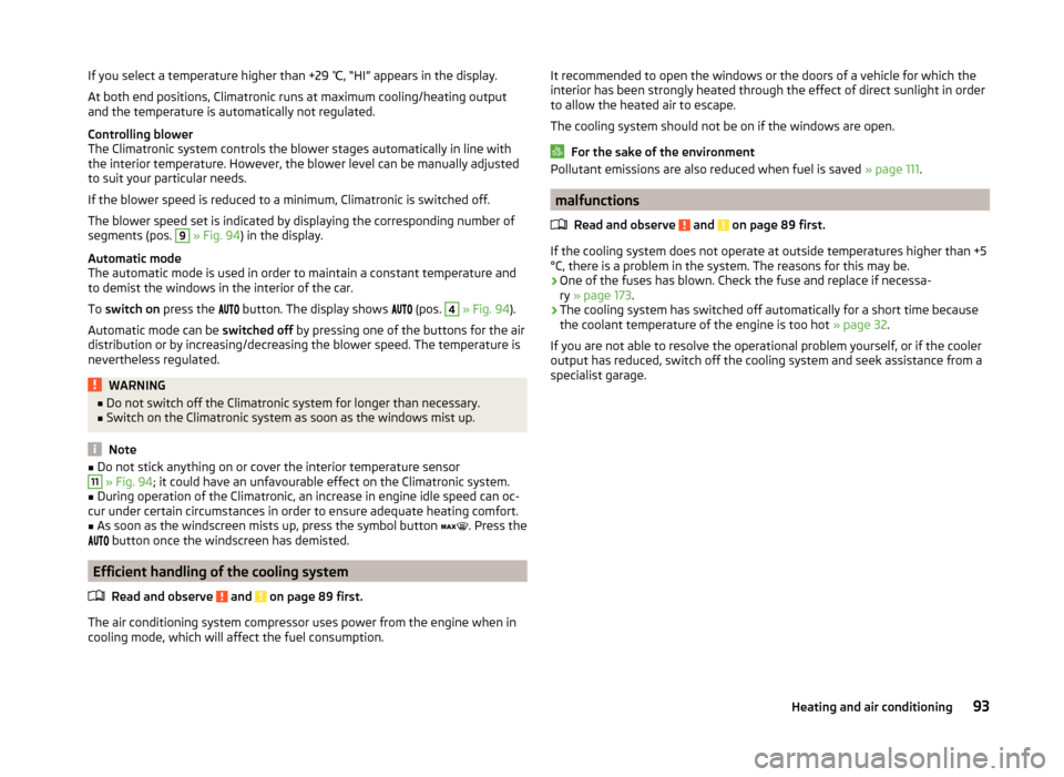
segments (pos. 9
» Fig. 94 ) in the display.
Automatic mode
The automatic mode is used in order to maintain a constant temperature and
to demist the windows in the interior of the car.
To switch on press the
button. The display shows
(pos.
4
» Fig. 94 ).
Automatic mode can be switched off by pressing one of the buttons for the air
distribution or by increasing/decreasing the blower speed. The temperature is
nevertheless regulated.
WARNING■ Do not switch off the Climatronic system for longer than necessary.■Switch on the Climatronic system as soon as the windows mist up.
Note
■Do not stick anything on or cover the interior temperature sensor11 » Fig. 94 ; it could have an unfavourable effect on the Climatronic system.■
During operation of the Climatronic, an increase in engine idle speed can oc-
cur under certain circumstances in order to ensure adequate heating comfort.
■
As soon as the windscreen mists up, press the symbol button
. Press the
button once the windscreen has demisted.
Efficient handling of the cooling system
Read and observe
and on page 89 first.
The air conditioning system compressor uses power from the engine when in
cooling mode, which will affect the fuel consumption.
It recommended to open the windows or the doors of a vehicle for which the
interior has been strongly heated through the effect of direct sunlight in order
to allow the heated air to escape.
The cooling system should not be on if the windows are open.
For the sake of the environment
Pollutant emissions are also reduced when fuel is saved » page 111.
malfunctions
Read and observe
and on page 89 first.
If the cooling system does not operate at outside temperatures higher than +5
°C, there is a problem in the system. The reasons for this may be.
› One of the fuses has blown. Check the fuse and replace if necessa-
ry » page 173 .
› The cooling system has switched off automatically for a short time because
the coolant temperature of the engine is too hot » page 32.
If you are not able to resolve the operational problem yourself, or if the cooler
output has reduced, switch off the cooling system and seek assistance from a
specialist garage.
93Heating and air conditioning
Page 105 of 204

The ŠKODA applications installed in a connected communications device (e.g.
phone, tablet, notebook) 1)
offer the possibility to further process the received
data.
Available applications and further information can be found on the ŠKODA
website..WARNING■ The national legal regulations for using mobile communication devices in
a vehicle must be observed.■
Do not fit the equipment or mounts to be connected onto airbag covers
or within the immediate deployment range of the airbags.
■
Never leave a connected device in the deployment area of an airbag, on a
seat, on the dash panel or any another area, from which it can be thrown
during a sudden braking manoeuvre, an accident or a collision - there is a
risk of injury.
Note
The Wi-Fi range is limited to the interior of the vehicle.
Connection with SmartGate
Read and observe
on page 102 first.
For a successful connection the following conditions must be met. Wi-Fi is turned on in the device to be connected.
The ignition is switched on.
Connect
›
Can enable the connected device to search for available Wi-Fi networks (see
operating instructions for the connected device).
›
In the found networks menu, select the connection to the
“SmartGate_ ... ”network 2)
.
›
Enter the password (the password is pre-set at the factory to the complete
Vehicle Identification Number - enter capital letters).
Disconnecting the connection
The connection to SmartGate can be ended in the following ways.
› By disconnecting the connected device from SmartGate.›By turning off the Wi-Fi in the connected device.›
By switching off the ignition and removing the key for more than 5 s (for ve-
hicles with starter button - by turning off the engine and opening the driver's
door).
Automatic connection
The connection to SmartGate is automatically restored under the following
conditions.
Wi-Fi is turned on in the device to be connected.
The ignition is switched on.
The device to be connected stores the password required for the connec-
tion check.
Connection problems
If the connection fails, check the following points.
› Are the conditions for a successful connection fulfilled?
› Is Smart Gate available in the list of available Wi-Fi networks?
› Has the password required for the connection check been entered?
› Is the password is required for the connection check correct?
› Is the device to be connected still connected to another Wi-Fi network?
If the above items are ok but the connection still fails, contact a ŠKODA part-
ner.
Note
Up to four devices can be connected to SmartGate at a time.
Smart Gate website
Read and observe
on page 102 first.
There is a special website for the SmartGate system.
The following address must be entered in the web browser of the connected device.
HTTP://192.168.123.1
1)
The applications support communication devices with the Android operating system version 4.0.x and
later and iOS 7.xx and higher.
2)
The last six symbols of the VIN vehicle identification number of your vehicle are displayed at position ....
102Using the system
Page 107 of 204
Driving
Starting-off and Driving
Starting and turning off the engine
Introduction
This chapter contains information on the following subjects:
Electronic immobilizer
104
Lock/unlock steering lock
104
Ignition on / off and start the engine
105
Switching off the engine
105
With the key in the ignition, the ignition can be switched on and off and the
engine can be started / stopped.
WARNING■ While driving with the engine stopped, the ignition must always be
switched on » page 105, Ignition on / off and start the engine .
■ With the ignition off, the steering may lock » page 104 - danger of an
accident!■
Do not withdraw the ignition key from the ignition lock until the vehicle
has come to a stop » page 107, Parking . Otherwise, the steering could be
blocked – risk of accident!
■
Never leave the key in the vehicle when you exit the vehicle. Unauthor-
ized persons, such as children, for example, could lock the car, turn on the
ignition or start the engine - there is a danger of injury, accidents and dam-
age!
■
Never leave the vehicle unattended with the engine running - there is
risk of accident, damage or theft!
■
Never switch off the engine before the vehicle is stationary – risk of acci-
dent!
WARNING■ Never (e.g. in garages) run the engine in a closed place - there is the dan-
ger of poisoning and death!■
Do not leave any items (e.g. cloths or tools) in the engine compartment.
This presents a fire hazard and the risk of engine damage.
■
Never cover the engine with additional insulation material (e.g. with a
cover) – risk of fire!
CAUTION
■ Only start the engine when the engine and the vehicle are stationary - there
is a danger of starter and engine damage!■
Do not push-start the engine – there is a risk of damaging the engine and
the catalytic converter. The battery from another vehicle can be used as a
jump-start aid » page 166.
Note
Do not warm up the engine while the vehicle is stationary. If possible, start
your journey as soon as the engine has started. Through this, the engine rea-
ches its operating temperature faster.
Electronic immobilizer
Read and observe
and on page 104 first.
The electronic immobilizer makes a possible attempted theft or unauthorizeduse of your vehicle more difficult.
An electronic chip is integrated in the head of the key. The immobiliser is deac-
tivated with the aid of this chip when the key is inserted in the ignition lock.
The electronic immobiliser is automatically activated when the ignition key is
withdrawn from the lock.
The engine will not start if a non-authorized ignition key is used.
The following message is shown in the information cluster display. Immobilizer active.
IMMOBILIZER
Lock/unlock steering lock
Read and observe
and on page 104 first.
The steering lock (steering lock) deters any attempted theft of your vehicle.
104Driving
Page 108 of 204

Locking›Withdraw the ignition key.›
Turn the steering wheel to the left or right until the steering lock clicks into
place.
Unlocking
›
Insert the key into the ignition lock.
›
Switch on the ignition » page 105.
The steering lock is unlocked.
If the ignition switch cannot be turned on, then turn the steering wheel back and forth slightly and thereby unlock the steering lock.
Ignition on / off and start the engine
Fig. 99
Positions of the vehicle key in the ignition lock
Read and observe and on page 104 first.
Positions of the vehicle key in the ignition lock » Fig. 99
Ignition switched off, engine switched off
Ignition switched on
Starting engine
Switching ignition on/off
›
Turn key to position
2
.
The ignition is switched on.
›
Turn key to position
1
.
The ignition is switched off.
Procedure for starting the engine
›
Firmly apply the handbrake.
›
For vehicles with manual transmission , shift gear stick to neutral, depress
the clutch pedal and hold it there until the engine starts.
123› On vehicles with
automatic transmission , place the selector lever in position
P or N and depress the brake pedal until the engine starts.›
Turn the key into position
3
to the stop and release immediately after the
engine has been started – do not apply the accelerator.
After letting go, the vehicle key will return to position
2
.
For vehicles with diesel engines the glow plug warning light
goes on during
starting. The engine can be started after the indicator light goes out.
If the engine does not start within 10 seconds, turn the key to position
1
. Re-
peat the start-up process after approx. half a minute.
Vehicles with the START-STOP system and manual gearbox
The engine will not start if the clutch pedal is not depressed.
The following message is shown in the information cluster display. Depress clutch to start.
CLUTCH
Vehicles with the START-STOP system and automatic gearbox
The engine will not start if the brake pedal is not depressed.
The following message is shown in the information cluster display. Depress brake to start.
BRAKE
Note
■ The engine running noises may louder at first be louder for a short time after
starting the cold engine. This is quite normal and is not an operating problem.■
You should not switch on any major electrical components during the heat-
ing period otherwise the vehicle battery will be drained unnecessarily.
Switching off the engine
Read and observe
and on page 104 first.
›
Stop the vehicle » page 107, Parking .
›
Turn key to position
1
» Fig. 99 on page 105 .
The engine and the ignition are switched off simultaneously.
For vehicles with automatic transmission, the ignition key can only be removed if the selector lever is in position P .
105Starting-off and Driving