light SKODA RAPID SPACEBACK 2014 1.G Workshop Manual
[x] Cancel search | Manufacturer: SKODA, Model Year: 2014, Model line: RAPID SPACEBACK, Model: SKODA RAPID SPACEBACK 2014 1.GPages: 204, PDF Size: 27.11 MB
Page 95 of 204
Setting the direction of the air outlet » page 90
›
Air flow to the windows
›
Air flow to the upper body
›
Air flow in the footwell
›
Airflow over the windows and into the footwell
Switch recirculation on/off » page 90
Switch the cooling system on/off
Note
■ The warning light in the button illuminates after activation, even if not all
of the conditions for the function of the cooling system have been met. By
lighting up of the warning light in the button, the operational readiness of the
cooling system is signalled.■
During operation of the air conditioning, an increase in engine idle speed may
occur under certain circumstances in order to ensure sufficient heating com-
fort.
Climatronic (automatic air conditioning)
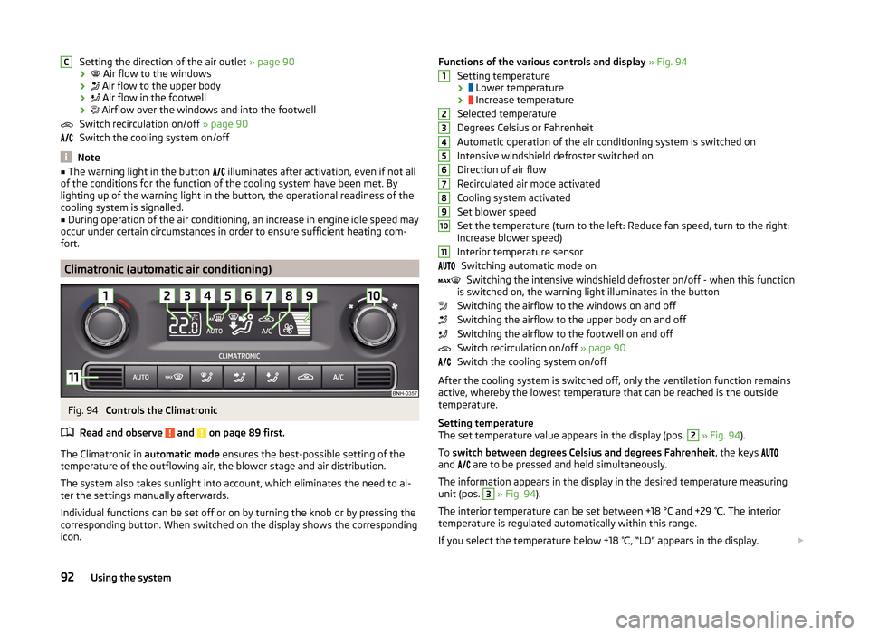
Fig. 94
Controls the Climatronic
Read and observe
and on page 89 first.
The Climatronic in automatic mode ensures the best-possible setting of the
temperature of the outflowing air, the blower stage and air distribution.
The system also takes sunlight into account, which eliminates the need to al-
ter the settings manually afterwards.
Individual functions can be set off or on by turning the knob or by pressing the
corresponding button. When switched on the display shows the corresponding
icon.
CFunctions of the various controls and display » Fig. 94
Setting temperature ›
Lower temperature
›
Increase temperature
Selected temperature
Degrees Celsius or Fahrenheit
Automatic operation of the air conditioning system is switched on
Intensive windshield defroster switched on
Direction of air flow
Recirculated air mode activated
Cooling system activated
Set blower speed
Set the temperature (turn to the left: Reduce fan speed, turn to the right:
Increase blower speed)
Interior temperature sensor Switching automatic mode on Switching the intensive windshield defroster on/off - when this function
is switched on, the warning light illuminates in the button
Switching the airflow to the windows on and off
Switching the airflow to the upper body on and off
Switching the airflow to the footwell on and off
Switch recirculation on/off » page 90
Switch the cooling system on/off
After the cooling system is switched off, only the ventilation function remains
active, whereby the lowest temperature that can be reached is the outside
temperature.
Setting temperature
The set temperature value appears in the display (pos. 2
» Fig. 94 ).
To switch between degrees Celsius and degrees Fahrenheit , the keys
and are to be pressed and held simultaneously.
The information appears in the display in the desired temperature measuring
unit (pos.
3
» Fig. 94 ).
The interior temperature can be set between +18 °C and +29 ℃. The interior
temperature is regulated automatically within this range.
If you select the temperature below +18 ℃, “LO” appears in the display.
123456789101192Using the system
Page 96 of 204
If you select a temperature higher than +29 ℃, “HI” appears in the display.
At both end positions, Climatronic runs at maximum cooling/heating output
and the temperature is automatically not regulated.
Controlling blower
The Climatronic system controls the blower stages automatically in line with the interior temperature. However, the blower level can be manually adjusted
to suit your particular needs.
If the blower speed is reduced to a minimum, Climatronic is switched off.
The blower speed set is indicated by displaying the corresponding number of
segments (pos. 9
» Fig. 94 ) in the display.
Automatic mode
The automatic mode is used in order to maintain a constant temperature and
to demist the windows in the interior of the car.
To switch on press the
button. The display shows
(pos.
4
» Fig. 94 ).
Automatic mode can be switched off by pressing one of the buttons for the air
distribution or by increasing/decreasing the blower speed. The temperature is
nevertheless regulated.
WARNING■ Do not switch off the Climatronic system for longer than necessary.■Switch on the Climatronic system as soon as the windows mist up.
Note
■Do not stick anything on or cover the interior temperature sensor11 » Fig. 94 ; it could have an unfavourable effect on the Climatronic system.■
During operation of the Climatronic, an increase in engine idle speed can oc-
cur under certain circumstances in order to ensure adequate heating comfort.
■
As soon as the windscreen mists up, press the symbol button
. Press the
button once the windscreen has demisted.
Efficient handling of the cooling system
Read and observe
and on page 89 first.
The air conditioning system compressor uses power from the engine when in
cooling mode, which will affect the fuel consumption.
It recommended to open the windows or the doors of a vehicle for which the
interior has been strongly heated through the effect of direct sunlight in order
to allow the heated air to escape.
The cooling system should not be on if the windows are open.
For the sake of the environment
Pollutant emissions are also reduced when fuel is saved » page 111.
malfunctions
Read and observe
and on page 89 first.
If the cooling system does not operate at outside temperatures higher than +5
°C, there is a problem in the system. The reasons for this may be.
› One of the fuses has blown. Check the fuse and replace if necessa-
ry » page 173 .
› The cooling system has switched off automatically for a short time because
the coolant temperature of the engine is too hot » page 32.
If you are not able to resolve the operational problem yourself, or if the cooler
output has reduced, switch off the cooling system and seek assistance from a
specialist garage.
93Heating and air conditioning
Page 98 of 204

Internal PhonebookRead and observe
on page 94 first.
An internal phonebook is part of the hands-free system. This phone phone-
book can be used depending on the type of mobile phone.
After the first connection of the telephone, the system begins to load the
phone book from the phone and the SIM card into the memory of the control
unit.
Each time the telephone has established a new connection with the hands-
free system, an update of the relevant phone book is performed. The updating
can take a few minutes. During this time the phone book, which was stored af-
ter the last update was completed, is available. Newly stored telephone num-
bers are only shown after the updating has ended.
The update is interrupted if a telephone event (e.g. incoming or outgoing call,
voice control dialogue) occurs during the updating procedure. After the tele-
phone event has ended, the updating starts anew.
The internal phonebook provides 2,500 free memory locations. Each contact
can contain up to 4 numbers.
If the number of contacts loaded exceeds 2,500, the phone book is not com-
plete.
Operating the phone on the multifunction steering wheel
Fig. 95
Multifunction steering wheel: Control buttons for the telephone
Read and observe
on page 94 first.
To minimize driver distraction when operating the telephone, the basic tele-
phone's functions can be set by simply operating the buttons located on the
steering wheel » Fig. 95.
This applies only if your vehicle has been equipped with the universal tele-
phone installation at the factory.
The buttons control the functions for the operating mode of the current tele-
phone.
If the side lights are switched on, the buttons on the multifunction steering
wheel are illuminated.Button / adjust- ment
wheel » Fig. 95ActionOperation
1Press briefly(MUTE )1Turn upwardsIncrease volume 95Communication and multimedia
Page 103 of 204
Music playback via Bluetooth®
The universal telephone pre-installation GSM II makes it possible to play back
music via Bluetooth ®
from the devices such as MP3 player, mobile phone or
notebook.
To ensure that music can be played via Bluetooth ®
, you must first pair the de-
vice with the hands-free system in the Phone - Bluetooth - Media player
menu.The music playback process is performed on the connected device.
The universal telephone pre-installation GSM II ensures that the music played back via the hands-free system can be controlled with the remote con-
trol » page 99 , Voice commands .
Note
The device being connected must support the Bluetooth ®
A2DP profile; refer
to the operating instructions for the relevant device being connected.
Operating the radio and navigation system on the multifunction steering wheel
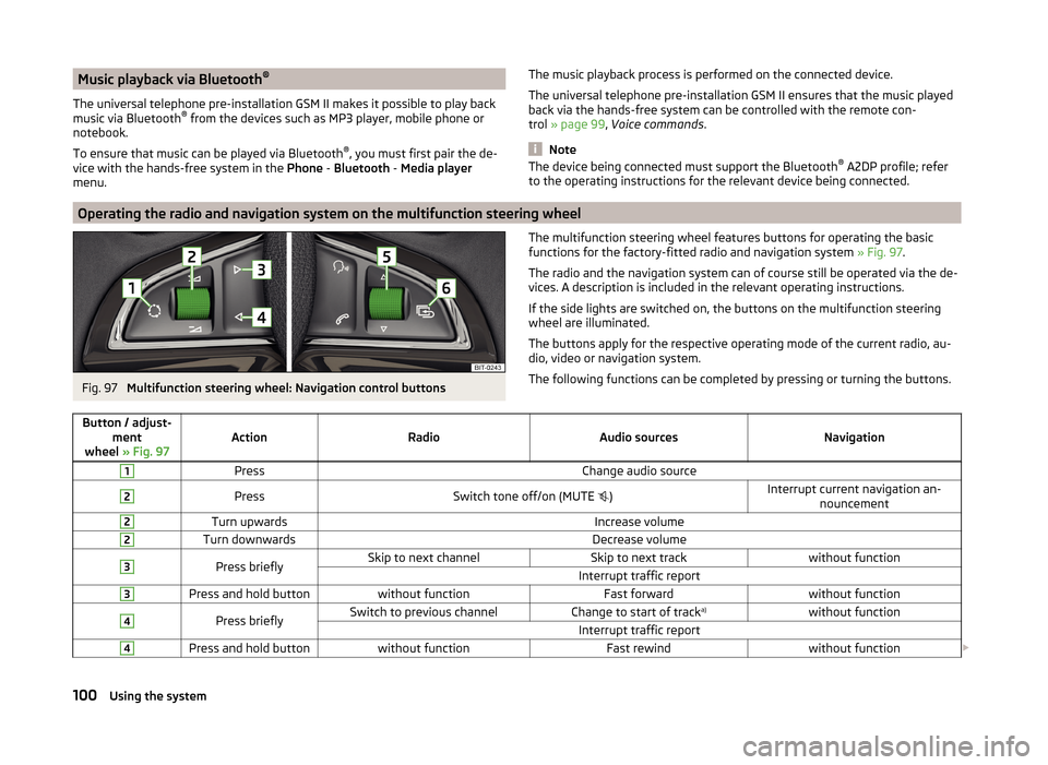
Fig. 97
Multifunction steering wheel: Navigation control buttons
The multifunction steering wheel features buttons for operating the basic
functions for the factory-fitted radio and navigation system » Fig. 97.
The radio and the navigation system can of course still be operated via the de-
vices. A description is included in the relevant operating instructions.
If the side lights are switched on, the buttons on the multifunction steering wheel are illuminated.
The buttons apply for the respective operating mode of the current radio, au-
dio, video or navigation system.
The following functions can be completed by pressing or turning the buttons.Button / adjust- ment
wheel » Fig. 97ActionRadioAudio sourcesNavigation
1PressChange audio source2PressSwitch tone off/on (MUTE )Interrupt current navigation an-
nouncement2Turn upwardsIncrease volume2Turn downwardsDecrease volume3Press brieflySkip to next channelSkip to next trackwithout functionInterrupt traffic report3Press and hold buttonwithout functionFast forwardwithout function4Press brieflySwitch to previous channelChange to start of track a)without functionInterrupt traffic report4Press and hold buttonwithout functionFast rewindwithout function
100Using the system
Page 108 of 204

Locking›Withdraw the ignition key.›
Turn the steering wheel to the left or right until the steering lock clicks into
place.
Unlocking
›
Insert the key into the ignition lock.
›
Switch on the ignition » page 105.
The steering lock is unlocked.
If the ignition switch cannot be turned on, then turn the steering wheel back and forth slightly and thereby unlock the steering lock.
Ignition on / off and start the engine
Fig. 99
Positions of the vehicle key in the ignition lock
Read and observe and on page 104 first.
Positions of the vehicle key in the ignition lock » Fig. 99
Ignition switched off, engine switched off
Ignition switched on
Starting engine
Switching ignition on/off
›
Turn key to position
2
.
The ignition is switched on.
›
Turn key to position
1
.
The ignition is switched off.
Procedure for starting the engine
›
Firmly apply the handbrake.
›
For vehicles with manual transmission , shift gear stick to neutral, depress
the clutch pedal and hold it there until the engine starts.
123› On vehicles with
automatic transmission , place the selector lever in position
P or N and depress the brake pedal until the engine starts.›
Turn the key into position
3
to the stop and release immediately after the
engine has been started – do not apply the accelerator.
After letting go, the vehicle key will return to position
2
.
For vehicles with diesel engines the glow plug warning light
goes on during
starting. The engine can be started after the indicator light goes out.
If the engine does not start within 10 seconds, turn the key to position
1
. Re-
peat the start-up process after approx. half a minute.
Vehicles with the START-STOP system and manual gearbox
The engine will not start if the clutch pedal is not depressed.
The following message is shown in the information cluster display. Depress clutch to start.
CLUTCH
Vehicles with the START-STOP system and automatic gearbox
The engine will not start if the brake pedal is not depressed.
The following message is shown in the information cluster display. Depress brake to start.
BRAKE
Note
■ The engine running noises may louder at first be louder for a short time after
starting the cold engine. This is quite normal and is not an operating problem.■
You should not switch on any major electrical components during the heat-
ing period otherwise the vehicle battery will be drained unnecessarily.
Switching off the engine
Read and observe
and on page 104 first.
›
Stop the vehicle » page 107, Parking .
›
Turn key to position
1
» Fig. 99 on page 105 .
The engine and the ignition are switched off simultaneously.
For vehicles with automatic transmission, the ignition key can only be removed if the selector lever is in position P .
105Starting-off and Driving
Page 109 of 204
CAUTIONDo not switch the engine off immediately at the end of your journey after the
engine has been operated over a prolonged period at high loads but leave it to
run at an idling speed for about 1 minute. This prevents any possible accumula-
tion of heat when the engine is switched off.
Note
After switching off the ignition, the radiator fan may intermittently continue to
operate for approx. 10 minutes.
Brakes and parking
Introduction
This chapter contains information on the following subjects:
Information on braking
106
Handbrake
107
Parking
107WARNING■ Greater physical effort is required for braking when the engine is switch-
ed off – risk of accident!■
The clutch pedal must be actuated when braking on a vehicle with man-
ual transmission, when the vehicle is in gear and at low revs. Otherwise,
the functionality of the brake system may be impaired – risk of accident!
■
When leaving the vehicle, never leave persons who might, for example,
release the handbrake or take the vehicle out of gear unattended in the ve-
hicle. The vehicle could then start to move – risk of accident!
■
Observe the recommendations on the new brake pads » page 111, New
brake pads .
CAUTION
Never let the brakes slip with light pressure on the pedal if braking is not nec-
essary. This causes the brakes to overheat and can also result in a longer brak-
ing distance and excessive wear.Information on braking
Read and observe
and on page 106 first.
Wear-and-tear
The wear of the brake pads is dependent on the operating conditions and driv-
ing style.
The brake pads wear more quickly if a lot of journeys are completed in towns
and over short distances or if a very sporty style of driving is adopted.
Under these severe conditions , the thickness of the brake pads must also be
checked by a specialist garage between service intervals.
Wet roads or road salt
The performance of the brakes can be delayed as the brake discs and brake
pads may be moist or have a coating of ice or layer of salt on them in winter.
The brakes are cleaned and dried by applying the brakes several times »
.
Corrosion
Corrosion on the brake discs and dirt on the bake pads occur if the vehicle has
been parked for a long period and if you do not make much use of the braking
system. The brakes are cleaned by applying the brakes several times »
.
Long or steep slopes
Before travelling a long distance with a steep gradient, reduce speed and shift
into the next lowest gear. As a result, the braking effect of the engine will be
used, reducing the load on the brakes. Any additional braking should be com-
pleted intermittently, not continuously.
Emergency brake display
If the brakes are applied in full and the control unit for the braking system con-
siders the situation to be dangerous for the following traffic, the brake light
flashes automatically.
After the speed was reduced below around 10 km/h or the vehicle was stop-
ped, the brake light stops flashing and the hazard warning light system
switches on. The hazard warning light system is switched off automatically af- ter accelerating or driving off again.
Faults in the brake surface
If it is found that the braking distance has suddenly become longer and that
the brake pedal can be depressed further, the brake system may be faulty.
Visit a specialist garage immediately and adjust your style of driving appropri-
ately, as you will not know the exact extent of the damage.
106Driving
Page 110 of 204
Low brake fluid level
An insufficient level of brake fluid may result in problems in the brake system.
The level of the brake fluid is monitored electronically » page 35,
Brake sys-
tem .
Brake booster
The brake booster increases the pressure generated with the brake pedal. The
brake booster only operates when the engine is running.WARNINGOnly apply the brakes for the purpose of drying and cleaning the brake
discs if the traffic conditions permit this. Do not place any other road users
in jeopardy.
Handbrake
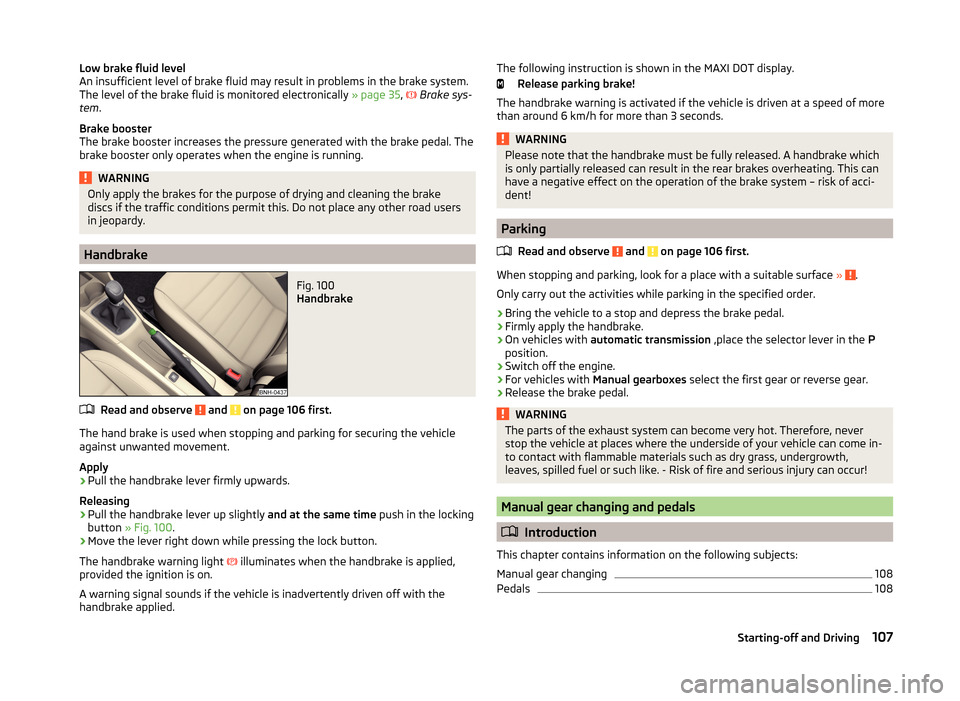
Fig. 100
Handbrake
Read and observe and on page 106 first.
The hand brake is used when stopping and parking for securing the vehicle
against unwanted movement.
Apply
›
Pull the handbrake lever firmly upwards.
Releasing
›
Pull the handbrake lever up slightly and at the same time push in the locking
button » Fig. 100 .
›
Move the lever right down while pressing the lock button.
The handbrake warning light
illuminates when the handbrake is applied,
provided the ignition is on.
A warning signal sounds if the vehicle is inadvertently driven off with the
handbrake applied.
The following instruction is shown in the MAXI DOT display.
Release parking brake!
The handbrake warning is activated if the vehicle is driven at a speed of more
than around 6 km/h for more than 3 seconds.WARNINGPlease note that the handbrake must be fully released. A handbrake which
is only partially released can result in the rear brakes overheating. This can
have a negative effect on the operation of the brake system – risk of acci-
dent!
Parking
Read and observe
and on page 106 first.
When stopping and parking, look for a place with a suitable surface » .
Only carry out the activities while parking in the specified order.
›
Bring the vehicle to a stop and depress the brake pedal.
›
Firmly apply the handbrake.
›
On vehicles with automatic transmission ,place the selector lever in the P
position.
›
Switch off the engine.
›
For vehicles with Manual gearboxes select the first gear or reverse gear.
›
Release the brake pedal.
WARNINGThe parts of the exhaust system can become very hot. Therefore, never
stop the vehicle at places where the underside of your vehicle can come in-
to contact with flammable materials such as dry grass, undergrowth,
leaves, spilled fuel or such like. - Risk of fire and serious injury can occur!
Manual gear changing and pedals
Introduction
This chapter contains information on the following subjects:
Manual gear changing
108
Pedals
108107Starting-off and Driving
Page 111 of 204

Manual gear changingFig. 101
Gear shift pattern of 5 gear or
6 gear manual gearbox
The individual gear positions are shown on the gear shift » Fig. 101.
The gear shift indicator must be observed when changing gear » page 43.
Always depress the clutch pedal all the way down. This prevents uneven wear
on the clutch.
Engaging reverse gear
›
Stop the vehicle.
›
The clutch pedal must be fully depressed.
›
Move the shift lever to the idle position, switch and press down.
›
Move the shift lever fully to the left and then forward into the Rposi-
tion » Fig. 101 .
The reversing lights will come on once the reverse gear is engaged, provided
the ignition is on.
WARNINGNever engage reverse gear when driving – risk of accident!
CAUTION
■ If not in the process of changing gear, do not leave your hand on the gear
shift lever while driving. The pressure from the hand can cause the gear shift
mechanism to wear excessively.■
When stopping on a slope, never try to keep the vehicle in position by using
the clutch and accelerator pedals – this may lead to damage to the clutch
parts.
Pedals
The operation of the pedals must not be hindered under any circumstances!
In the driver's foot well, only a foot mat, which is attached to the two corre-
sponding attachment points, may be used.
Only use factory-supplied foot mats or foot mats from the range of
ŠKODAOriginal Accessories, which are fitted to two the two required attach-
ment points.WARNINGNo objects may be placed in the driver's foot well – risk due to obstruction
or limitation of pedal operation!
Automatic gearbox
Introduction
This chapter contains information on the following subjects:
Modes and use of selector lever
109
Selector lever lock
109
Manual shifting of gears (Tiptronic)
110
Starting-off and driving
110
The automatic transmission performs automatic gear changes.
The modes for the automatic transmission can be adjusted by the driver by
means of the selector lever.
WARNING■ Never accelerate when the mode for moving forward is set with the se-
lector lever - there is a risk of accident!■
Never move the selector lever to mode R or P when driving – risk of acci-
dent!
■
When the vehicle is stationary and the engine is running, the vehicle must
be held in mode D, S or R with the brake pedal. Even when the engine is
idling, the power transmission is never completely interrupted – the vehicle
crawls forward.
■
When leaving the vehicle, the selector lever is always to be put in the P
mode. Otherwise the vehicle could then start to move and potentially cause
an accident.
108Driving
Page 112 of 204
CAUTION■If the selector lever is moved to mode N while driving, the accelerator pedal
must be released and you will need to wait until the engine has reached its
idling speed before moving the selector lever to a forward driving mode again.■
When the outdoor temperature is below -10 ° C, the selector lever, when
starting, must always be in P mode.
■
When stopping on a slope, never try to keep the vehicle in position by using
the accelerator pedal – this may lead to gear damage.
Note
After the ignition is switched off, the ignition key can only be withdrawn if the
selector lever is in the position P.
Modes and use of selector lever
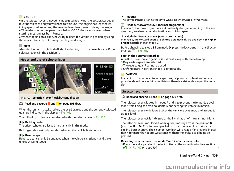
Fig. 102
Selection lever / lock button / display
Read and observe
and on page 108 first.
When the ignition is switched on, the gearbox mode and the currently selected
gear are indicated in the display » Fig. 102.
The following modes can be selected with the selector lever » Fig. 102.
P
– Parking mode
The driven wheels are locked mechanically in this mode.
Parking mode must only be selected when the vehicle is stationary.
R
– Reverse gear
Reverse gear can only be engaged when the vehicle is stationary and the en-
gine is at idling speed.
N – Neutral
The power transmission to the drive wheels is interrupted in this mode.D
- Mode for forwards travel (normal programme)
In mode D, the forward gears are automatically changed according to the en-
gine load, accelerator pedal actuation and driving speed.
S
- Mode for forwards travel (sports programme)
In mode S, the forward gears are shifted automatically up and down at higher
engine speeds than in mode D.
Before changing to mode S from mode D, press the lock button in the direction
of arrow
1
» Fig. 102 .
Fault in the automatic gearbox
A fault in the automatic gearbox is noticeable e.g. with the following.
› Only certain gears are selected.
› The reverse gear
R cannot be used.
› Shifting gears in Tiptronic mode is not possible.
CAUTION
If a fault occurs on the automatic gearbox, help from a professional service
provider should be sought immediately - there is a risk of damaging the vehi-
cle.
Selector lever lock
Read and observe
and on page 108 first.
The selector lever is locked in modes P and N to prevent the forwards travel
mode from being selected accidentally and setting the vehicle in motion.
The selector lever is only locked when the vehicle is stationary and at speeds
up to 5 km/h.
The selector lever lock is indicated by the illumination of the warning light.
The selector lever is not locked when quickly moving across the position N
(e.g. from R to D). This, for example, helps to rock out a vehicle that is stuck,
e.g. in a bank of snow. The selector lever lock will engage if the lever is in posi-
tion N for more than approx. 2 seconds without the brake pedal being de-
pressed.
Releasing selector lever from mode P or N (selector lever lock)
›
Press the brake pedal and the lock button at the same time in the direction
of
1
» Fig. 102 on page 109 .
109Starting-off and Driving
Page 116 of 204
Assist systems
Braking and stabilisation systems
Introduction
This chapter contains information on the following subjects:
Electronic Stability Control (ESC)
113
Anti-lock Braking System (ABS)
113
Traction Control System (TCS)
113
Electronic Differential Lock (EDL)
114
Hydraulic Brake Assist (HBA)
114
Hill Hold Control (HHC)
114
This chapter deals with the functions of the braking and stabilisation systems,
with the error indicator referred to in chapter » page 34, Indicator lights .
The braking and stabilisation systems are automatically activated each time
the ignition is switched on.
WARNING■ A lack of fuel can cause irregular engine running or cause the engine to
shut down. The brake assist systems would then fail to function – risk of
accident!■
The increased safety provided by the brake assist systems must not
tempt you to take safety risks – risk of accident!
■
Adjust the speed and driving style to the current visibility, weather, road
and traffic conditions.
Electronic Stability Control (ESC)
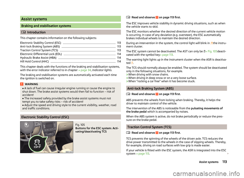
Fig. 105
Buttons for the ESC system: Acti-
vating/deactivating TCS
Read and observe on page 113 first.
The ESC improves vehicle stability in dynamic driving situations, such as when the vehicle starts to skid.
The ESC monitors whether the desired direction of the current vehicle motion
is occurring. In case of any deviation (e.g. oversteer), the ESC automatically
brakes individual wheels to maintain the desired direction.
During an intervention in the system, the control light will blink in
the instru-
ment cluster.
The ESC system cannot be deactivated. The AST can only be
» Fig. 105 deacti-
vated with the symbol key » page 113.
The warning light lights up in the instrument cluster when the ASR is deactiva- ted .
The TCS should normally always be enabled. The system should be deactivated
only in the following situations, for example.
› When driving with snow chains.
› When driving in deep snow or on a very loose surface.
› When “rocking a car free” when it has become stuck.
Anti-lock Braking System (ABS)
Read and observe
on page 113 first.
ABS prevents the wheels from locking when braking. Thereby, it helps the
driver to maintain control of the vehicle.
The intervention of the ABS is noticeable from the pulsating movements of
the brake pedal which is accompanied by noises.
When the ABS system is active, do not brake periodically or reduce the pres-
sure on the brake pedal.
Traction Control System (TCS)
Read and observe
on page 113 first.
TCS prevents the spinning of the wheels of the driven axle. TCS reduces thedrive power transmitted to the wheels in the case of slipping wheels. Thereby,
for example, driving on road surfaces with low grip is made easier.
If your vehicle is fitted with the ESC system, the ASR is integrated into the ESC
system » page 113 .
113Assist systems