brakes SKODA RAPID SPACEBACK 2014 1.G Owner's Manual
[x] Cancel search | Manufacturer: SKODA, Model Year: 2014, Model line: RAPID SPACEBACK, Model: SKODA RAPID SPACEBACK 2014 1.GPages: 204, PDF Size: 27.11 MB
Page 5 of 204
Table of Contents
Board literature4
Notes
5
Structure and more information about the
Operating Instructions
6
Abbreviations
Safety
Passive Safety
8
General information
8
Correct and safe seated position
9
Seat belts
12
Using seat belts
12
Inertia reels and belt tensioners
15
Airbag system
16
Description of the airbag system
16
Airbag overview
17
Deactivating airbags
20
Transporting children safely
22
Child seat
22
Fastening systems
25
Using the system
Cockpit
29
Overview
28
Instruments and Indicator Lights
30
Instrument cluster
30
Indicator lights
34
Information system
41
Driver information system
41
Multifunction display (MFD)
43MAXI DOT display46Service interval display47
Unlocking and opening
49
Unlocking and locking
49
Anti-theft alarm system
53
Luggage compartment lid
54
Power windows
55
Mechanical windows
57
Lights and visibility
58
Lights
58
Interior lighting
63
Visibility
64
Windscreen wipers and washers
65
Rear mirror
67
Seats and head restraints
69
Seats and head restraints
69
Seat features
71
Transporting and practical equipment
73
Useful equipment
73
Luggage compartment
80
Variable loading floor in the luggage
compartment (Estate)
85
Roof rack
88
Heating and air conditioning
89
Heating, ventilation, cooling
89
Communication and multimedia
94
Universal telephone installation GSM II
94
Voice control
98
Multimedia
99
SmartGate
101
Driving
Starting-off and Driving
104
Starting and turning off the engine
104
Brakes and parking
106Manual gear changing and pedals107Automatic gearbox108
Retraction and economical driving
111
Driving through water and driving off made-
up roads
111
Assist systems
113
Braking and stabilisation systems
113
Parking aid
114
Cruise Control System
115
START-STOP
116
Tyre pressure monitoring
119
Hitch and trailer
120
Hitch
120
Trailer
125
General Maintenance
Care and maintenance
128
Service work, adjustments and technical alterations
128
Washing vehicle
131
Cleaning vehicle exterior
132
Interior care
136
Inspecting and replenishing
138
Fuel
138
Engine compartment
141
Engine oil
144
Coolant
146
Brake fluid
147
Vehicle battery
148
Wheels
152
Tyres and wheel rims
152
Manufacturer-approved tyre variants
155
Winter operation
1562Table of Contents
Page 78 of 204

Fig. 64
Cup holder in rear armrest
Read and observe on page 73 first.
Two beverage containers can be placed into the cup holder.
Placement of the cup holders » Fig. 63 and » Fig. 64
In the front centre console
In the rear centre console
In the rear armrest
WARNING■ Do not use any cups or beakers which are made of brittle material (e.g.
glass, porcelain). This could lead to injuries in the event of an accident.■
Never put hot cups in the cup holder. If the vehicle moves, they may spill –
risk of scalding!
■
No objects should be placed in the holders that might endanger the vehi-
cle's occupants if the vehicle brakes suddenly or the vehicle is in collision.
CAUTION
Do not leave open beverage containers in the cup holder during the journey.
There is a risk of spilling e.g. when braking which may cause damage to the
electrical components or seat upholstery.ABCCigarette lighterFig. 65
Cigarette lighter
Read and observe on page 73 first.
Using the system
›
Press in the button in the cigarette lighter » Fig. 65.
›
Wait until the button pops forward.
›
Remove the cigarette lighter immediately and use.
›
Place the cigarette lighter back into the socket.
The cigarette lighter also operates if the ignition is switched off »
.
WARNING■
When leaving the vehicle, never leave persons who are not completely in-
dependent, such as children, unattended in the vehicle. These could oper-
ate the lighter and get burned, start a fire or damage the interior.■
Take care when using the cigarette lighter! Improper usage can cause
burns.
Note
The cigarette lighter socket can also be used as a 12- volt socket for electrical
appliances » page 76, 12-Volt power outlet .75Transporting and practical equipment
Page 109 of 204
CAUTIONDo not switch the engine off immediately at the end of your journey after the
engine has been operated over a prolonged period at high loads but leave it to
run at an idling speed for about 1 minute. This prevents any possible accumula-
tion of heat when the engine is switched off.
Note
After switching off the ignition, the radiator fan may intermittently continue to
operate for approx. 10 minutes.
Brakes and parking
Introduction
This chapter contains information on the following subjects:
Information on braking
106
Handbrake
107
Parking
107WARNING■ Greater physical effort is required for braking when the engine is switch-
ed off – risk of accident!■
The clutch pedal must be actuated when braking on a vehicle with man-
ual transmission, when the vehicle is in gear and at low revs. Otherwise,
the functionality of the brake system may be impaired – risk of accident!
■
When leaving the vehicle, never leave persons who might, for example,
release the handbrake or take the vehicle out of gear unattended in the ve-
hicle. The vehicle could then start to move – risk of accident!
■
Observe the recommendations on the new brake pads » page 111, New
brake pads .
CAUTION
Never let the brakes slip with light pressure on the pedal if braking is not nec-
essary. This causes the brakes to overheat and can also result in a longer brak-
ing distance and excessive wear.Information on braking
Read and observe
and on page 106 first.
Wear-and-tear
The wear of the brake pads is dependent on the operating conditions and driv-
ing style.
The brake pads wear more quickly if a lot of journeys are completed in towns
and over short distances or if a very sporty style of driving is adopted.
Under these severe conditions , the thickness of the brake pads must also be
checked by a specialist garage between service intervals.
Wet roads or road salt
The performance of the brakes can be delayed as the brake discs and brake
pads may be moist or have a coating of ice or layer of salt on them in winter.
The brakes are cleaned and dried by applying the brakes several times »
.
Corrosion
Corrosion on the brake discs and dirt on the bake pads occur if the vehicle has
been parked for a long period and if you do not make much use of the braking
system. The brakes are cleaned by applying the brakes several times »
.
Long or steep slopes
Before travelling a long distance with a steep gradient, reduce speed and shift
into the next lowest gear. As a result, the braking effect of the engine will be
used, reducing the load on the brakes. Any additional braking should be com-
pleted intermittently, not continuously.
Emergency brake display
If the brakes are applied in full and the control unit for the braking system con-
siders the situation to be dangerous for the following traffic, the brake light
flashes automatically.
After the speed was reduced below around 10 km/h or the vehicle was stop-
ped, the brake light stops flashing and the hazard warning light system
switches on. The hazard warning light system is switched off automatically af- ter accelerating or driving off again.
Faults in the brake surface
If it is found that the braking distance has suddenly become longer and that
the brake pedal can be depressed further, the brake system may be faulty.
Visit a specialist garage immediately and adjust your style of driving appropri-
ately, as you will not know the exact extent of the damage.
106Driving
Page 110 of 204
Low brake fluid level
An insufficient level of brake fluid may result in problems in the brake system.
The level of the brake fluid is monitored electronically » page 35,
Brake sys-
tem .
Brake booster
The brake booster increases the pressure generated with the brake pedal. The
brake booster only operates when the engine is running.WARNINGOnly apply the brakes for the purpose of drying and cleaning the brake
discs if the traffic conditions permit this. Do not place any other road users
in jeopardy.
Handbrake
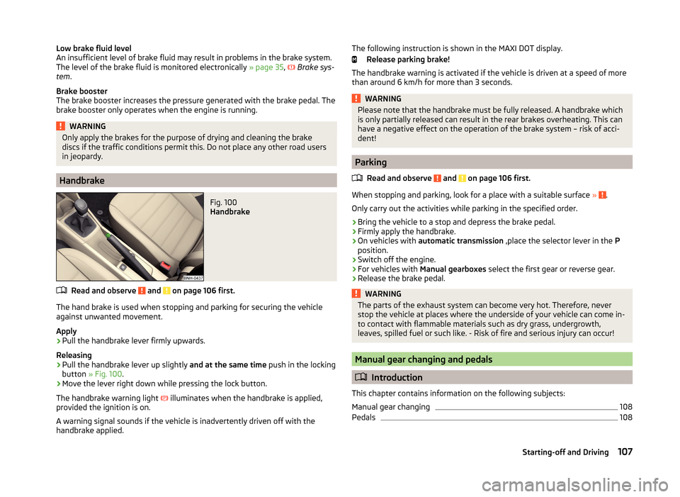
Fig. 100
Handbrake
Read and observe and on page 106 first.
The hand brake is used when stopping and parking for securing the vehicle
against unwanted movement.
Apply
›
Pull the handbrake lever firmly upwards.
Releasing
›
Pull the handbrake lever up slightly and at the same time push in the locking
button » Fig. 100 .
›
Move the lever right down while pressing the lock button.
The handbrake warning light
illuminates when the handbrake is applied,
provided the ignition is on.
A warning signal sounds if the vehicle is inadvertently driven off with the
handbrake applied.
The following instruction is shown in the MAXI DOT display.
Release parking brake!
The handbrake warning is activated if the vehicle is driven at a speed of more
than around 6 km/h for more than 3 seconds.WARNINGPlease note that the handbrake must be fully released. A handbrake which
is only partially released can result in the rear brakes overheating. This can
have a negative effect on the operation of the brake system – risk of acci-
dent!
Parking
Read and observe
and on page 106 first.
When stopping and parking, look for a place with a suitable surface » .
Only carry out the activities while parking in the specified order.
›
Bring the vehicle to a stop and depress the brake pedal.
›
Firmly apply the handbrake.
›
On vehicles with automatic transmission ,place the selector lever in the P
position.
›
Switch off the engine.
›
For vehicles with Manual gearboxes select the first gear or reverse gear.
›
Release the brake pedal.
WARNINGThe parts of the exhaust system can become very hot. Therefore, never
stop the vehicle at places where the underside of your vehicle can come in-
to contact with flammable materials such as dry grass, undergrowth,
leaves, spilled fuel or such like. - Risk of fire and serious injury can occur!
Manual gear changing and pedals
Introduction
This chapter contains information on the following subjects:
Manual gear changing
108
Pedals
108107Starting-off and Driving
Page 113 of 204
Just depress the brake pedal, if you would like to change from the mode N to
D .
Defective selector lever lock
If the selector lever lock is defective or its power supply is interrupted (e.g. dis-
charged vehicle battery, faulty fuse), the selector lever can no longer be moved
out of position P in the normal manner and the vehicle can no longer be driven.
The selector lever must be emergency released » page 171.
Note
If you want to move the selector lever from mode P to mode D or vice versa,
move the selector lever quickly. This prevents modes R or N from being acci-
dentally selected.
Manual shifting of gears (Tiptronic)
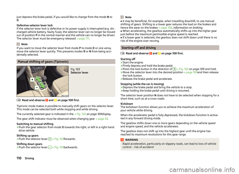
Fig. 103
Selector lever
Read and observe and on page 108 first.
Tiptronic mode makes it possible to manually shift gears on the selector lever.
This mode can be selected both while stopping and while driving.
The currently selected gear is indicated in the » Fig. 102 on page 109 display.
The gear shift indicator must be observed when changing gear » page 43.
Switching to manual shifting
›
Push the gear selector from mode D towards the right, or left in a right-hand
drive vehicle.
Shifting up gears
›
Push the selector lever
+
» Fig. 103 forwards.
Shifting down gears
›
Push the selector lever
-
» Fig. 103 backwards.
Note■
It may be beneficial, for example, when travelling downhill, to use manual
shifting of gears. Shifting to a lower gear reduces the load on the brakes and
hence the wear on the brakes » page 106, Information on braking .■
When accelerating, the gearbox automatically shifts up into the higher gear
just before the maximum permissible engine speed is reached.
■
If a lower gear is selected, the gearbox does not shift down until there is no
risk of the engine over-revving.
Starting-off and driving
Read and observe
and on page 108 first.
Starting off
›
Start the engine.
›
Firmly depress and hold the brake pedal.
›
Press the lock button in the direction of
1
» Fig. 102 on page 109 and hold.
›
Move the selector lever into the desired position » page 109and then release
the lock button.
›
Release the brake pedal and accelerate.
Stopping (while the car is moving)
›
Depress the brake pedal and bring the vehicle to a stop.
›
Keep holding the brake pedal until driving is resumed.
The selector lever position N does not have to be selected when stopping for a
short time, such as at a cross roads.
Kickdown
The kickdown function allows you to achieve the maximum acceleration of
your vehicle while driving.
When the accelerator pedal is fully depressed, the kickdown function is activa-
ted in any forward driving mode.
The gearbox shifts down one or more gears depending on the vehicle speed
and engine speed, and the vehicle accelerates.
The gearbox does not shift up into the highest gear until the engine has
reached its maximum revolutions for this gear range.
WARNINGRapid acceleration, particularly on slippery roads, can lead to loss of vehicle
control – risk of accident!110Driving
Page 116 of 204
Assist systems
Braking and stabilisation systems
Introduction
This chapter contains information on the following subjects:
Electronic Stability Control (ESC)
113
Anti-lock Braking System (ABS)
113
Traction Control System (TCS)
113
Electronic Differential Lock (EDL)
114
Hydraulic Brake Assist (HBA)
114
Hill Hold Control (HHC)
114
This chapter deals with the functions of the braking and stabilisation systems,
with the error indicator referred to in chapter » page 34, Indicator lights .
The braking and stabilisation systems are automatically activated each time
the ignition is switched on.
WARNING■ A lack of fuel can cause irregular engine running or cause the engine to
shut down. The brake assist systems would then fail to function – risk of
accident!■
The increased safety provided by the brake assist systems must not
tempt you to take safety risks – risk of accident!
■
Adjust the speed and driving style to the current visibility, weather, road
and traffic conditions.
Electronic Stability Control (ESC)
Fig. 105
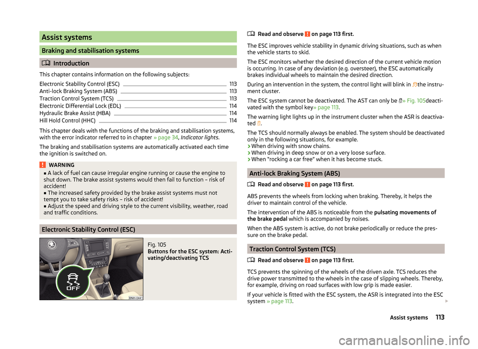
Buttons for the ESC system: Acti-
vating/deactivating TCS
Read and observe on page 113 first.
The ESC improves vehicle stability in dynamic driving situations, such as when the vehicle starts to skid.
The ESC monitors whether the desired direction of the current vehicle motion
is occurring. In case of any deviation (e.g. oversteer), the ESC automatically
brakes individual wheels to maintain the desired direction.
During an intervention in the system, the control light will blink in
the instru-
ment cluster.
The ESC system cannot be deactivated. The AST can only be
» Fig. 105 deacti-
vated with the symbol key » page 113.
The warning light lights up in the instrument cluster when the ASR is deactiva- ted .
The TCS should normally always be enabled. The system should be deactivated
only in the following situations, for example.
› When driving with snow chains.
› When driving in deep snow or on a very loose surface.
› When “rocking a car free” when it has become stuck.
Anti-lock Braking System (ABS)
Read and observe
on page 113 first.
ABS prevents the wheels from locking when braking. Thereby, it helps the
driver to maintain control of the vehicle.
The intervention of the ABS is noticeable from the pulsating movements of
the brake pedal which is accompanied by noises.
When the ABS system is active, do not brake periodically or reduce the pres-
sure on the brake pedal.
Traction Control System (TCS)
Read and observe
on page 113 first.
TCS prevents the spinning of the wheels of the driven axle. TCS reduces thedrive power transmitted to the wheels in the case of slipping wheels. Thereby,
for example, driving on road surfaces with low grip is made easier.
If your vehicle is fitted with the ESC system, the ASR is integrated into the ESC
system » page 113 .
113Assist systems
Page 117 of 204
NoteFor vehicles without stabilization control (ESC), during a TCS intervention the
control indicator blinks in the instrument cluster.
Electronic Differential Lock (EDL)
Read and observe
on page 113 first.
EDL prevents the turning of the respective wheel of the driven axle. EDL
brakes the spinning wheel, if necessary, and transmits the driving force to the
other driving wheel. Driving becomes easier on road surfaces with different
traction under each wheel of the driven axle.
The EDL switches off automatically in order to avoid excessive heat generation
on the brake of the wheel being braked. The vehicle can continue to be driven
and has the same characteristics as a vehicle not fitted with EDL. Once the
brakes have cooled down, there is an automatic re-activation of EDL.
Hydraulic Brake Assist (HBA)
Read and observe
on page 113 first.
The HBA increases the braking effect and helps to reduce the braking dis-
tance.
The HBA is activated by the very quick operation of the brake pedal. In order to
achieve the shortest possible braking distance, the brake pedal must be ap-
plied firmly until the vehicle has come to a standstill.
The HBA function is automatically deactivated when the brake pedal is re-
leased.
Hill Hold Control (HHC)
Read and observe
on page 113 first.
When driving on slopes, HHC allows you to move your foot from the brake ped-al to the accelerator pedal without having to use the handbrake.
The system holds the brake pressure produced by the activation of the brake pedal for approx. 2 seconds after the brake pedal is released.
The brake pressure drops gradually the more you operate the accelerator ped-
al. If the vehicle does not start off within 2 seconds, it starts to roll back.
The HHC is active from a 5% slope if the driver's door is closed. HHC is always
only active on slopes when in forward or reverse start off.
Parking aid
Introduction
This chapter contains information on the following subjects:
Function
115
Activation/deactivation
115
The parking aid (hereinafter referred to only as a system) draws attention via
acoustic signals and an indication in the radio or navigation display when ma-
noeuvring around obstacles in the vicinity of the vehicle.
The system uses ultrasound waves to calculate the distance between the
bumper and an obstacle. The ultrasonic sensors are integrated in the rear
bumper » Fig. 106 on page 115 .
WARNING■
The system only serves as an assistance and does not relieve the driver
of the responsibility for the vehicle operation.■
Moving persons or objects may not be recognised by the system sensors.
■
Under certain circumstances, surfaces of certain objects and types of
clothing cannot reflect the system signals. For this reason, such people or
objects may not be recognised by the system sensors.
■
External noise sources may affect the signals of the system sensors. Un-
der adverse conditions, this may cause objects or people to be not recog-
nised by the system.
■
Before reversing, you should make sure that there are no small obstacles,
such as rocks, thin posts, trailer draw-bars etc. behind your vehicle. Such
obstacles may not be recognised by the system sensors.
CAUTION
■ Keep the system sensors clean, snow-and ice-free and do not cover with any
objects of any kind, otherwise the system functioning may be impaired.■
Under adverse weather conditions (heavy rain, water vapour, very low or
high temperatures etc.), the system function may be limited - “incorrect recog-
nition of obstacle”.
■
Additionally installed accessories such as e.g. bicycle carriers can impair the
system function.
114Driving
Page 129 of 204
Loading a trailer
The vehicle/trailer combination must be balanced. Whereby the maximum per-
missible draw bar load must be utilised. If the draw bar load is too low, it jeop-
ardises the performance of the vehicle/trailer combination.
Distribution of the load
Distribute the load in the trailer in such a way that heavy items are located as
close to the axle as possible. Secure the items from slipping.
The distribution of the weight is very poor if your vehicle is unladen and the
trailer is laden. Maintain a particularly low speed if you cannot avoid driving
with this combination.
Tyre pressure
Correct the tyre inflation pressure on your vehicle for a “full load” » page 153.
Towing capacity and trailer weight
The permissible trailer load must not be exceeded under any circumstan-
ces » page 181 , Technical data .
The details given in the vehicle's technical documentation always take prece-
dence over the details in the Owner's Manual.
The trailer loads specified apply only to altitudes up to 1,000 metres above
mean sea level.
The engine output falls as altitude increases, as does the vehicle's climbing
power. Therefore, for every additional 1,000 m in height (or part), the maximum
permissible towed weight must be reduced by 10%.
The towed weight is made up of the actual weights of the loaded towing vehi-
cle and the loaded trailer.
The trailer and draw bar load information on the type plate of the towing de-
vice is merely a test value for the towing device. The vehicle-specific values
are detailed in the vehicle documents.WARNING■ The maximum permissible axle and drawbar load and the permissible
weight of the trailer must not exceed - this could cause an accident!■
A sliding cargo can significantly adversely affect stability and driving safe-
ty - there is a risk of accident!
Towing a trailer
Driving speed
For safety reasons, do not drive faster than 80 km/h when towing a trailer.
Immediately reduce your speed as soon as even the slightest swaying of the
trailer is detected. Never attempt to stop the trailer from “swaying” by acceler-
ating.
Brakes
Apply the brakes in good time! If the trailer is fitted with a trailer brake, apply
the brakes gently at first, then brake firmly. This will avoid brake jolts resulting
from the trailer wheels locking.
On downhill sections shift down a gear in good time to also use the engine as
a brake.
Engine overheating
If the needle for the coolant temperature gauge moves into the right-hand
area or the red area of the scale, the speed must be reduced immediately.
Stop and switch off the engine if the warning light illuminates or starts to
blink in the instrument cluster.
The following guidelines must be observed » page 36.
The coolant temperature level can be reduced by switching on the heating.WARNING■ Always drive particularly carefully with the trailer.■Adapt your speed to the conditions of the road surface and to the traffic
situation.
CAUTION
If you tow a trailer frequently, you should also have your vehicle inspected be-
tween service intervals.
Anti-theft alarm system
When the vehicle is locked, the alarm is activated when the electrical connec-
tion to the trailer is interrupted.
Always switch off the anti-theft alarm system before a trailer is coupled or un-
coupled » page 53 .
126Driving
Page 133 of 204
ŠKODA Service Partners are liable for any defects of ŠKODA Genuine Accesso-
ries for a period of 2 years after installation or delivery in accordance with the
materials defect liability, unless agreed otherwise in the purchase agreement
or any other agreements. You should keep the approved warranty certificate
and the invoices for these accessories for this period of time, so that the com-
mencement of the term can be verified.
ŠKODA Service Partners also stock a range of suitable car care products and all
parts that are subject to natural wear-and-tear, such as tyres, batteries, bulbs
and wiper blades.
Note
The accessories authorised by the company ŠKODA AUTO a.s. will be offered
by the ŠKODA Partners in all countries where the company ŠKODA AUTO a.s.
has a sales and after-sales service network. This will usually be in the form of a
printed catalogue of ŠKODA Genuine Accessories, in the form of separate prin-
ted brochures or in the form of ŠKODA Genuine Accessories on the ŠKODA
Partner websites.
Spoiler
Read and observe
on page 128 first.
If your new vehicle is fitted with a spoiler on the front bumper in combination
with the spoiler on the luggage compartment lid, then the following instruc-
tions must be adhered to.
› For safety reasons, the vehicle must only be fitted with a spoiler on the front
bumper in combination with the associated spoiler on the luggage compart-
ment lid.
› This kind of spoiler cannot be left on the front bumper either on its own, in
combination with another spoiler not on the luggage compartment lid or in
combination with an unsuitable spoiler on the luggage compartment lid.
› We recommend that you consult the ŠKODA Service Partner for any repairs
to or replacement, addition or removal of spoilers.
WARNING■ If work on your vehicle's spoilers is not carried out properly, this can lead
to operational faults - risk of accident and serious injuries!■
If a front spoiler, full wheel trim, etc. is mounted retrospectively, it must
be ensured that the air supply to the front wheel brakes is not reduced.
The front brakes may overheat, which can have a negative impact on the
functioning of the braking system – risk of accident!
Airbags
Read and observe
on page 128 first.
The system components of the airbag system can be situated in the front
bumper, doors, front seats, roof lining or body.
WARNINGAny work on the airbag system, including the installation and removal of
system components due to other repair work (e.g. removal of the steering
wheel), must only be carried out by a specialist garage.■
Modifications, repairs and technical alterations that have been carried out
unprofessionally can cause damage and operational faults, and can also se-
riously impair the effectiveness of the airbag system – risk of accident and
fatal injury!
■
The airbag system must then be replaced if the airbag has been deployed.
Airbag modules cannot be repaired.
WARNINGInformation on the use of the airbag system■It is prohibited to manipulate individual parts of the airbag system, as this
might result in the airbag being deployed.■
Never install any airbag parts into the vehicle that have been removed
from old cars or have been recycled.
■
Never install damaged airbag parts in the vehicle. The airbags may then
not be deployed properly or even at all in the event of an accident.
■
No modifications of any kind may be made to parts of the airbag system.
WARNING■ A change to the vehicle's wheel suspension, including the use of non-ap-
proved wheels and tyre combinations, can alter the functioning of the air-
bag system - risk of accident and fatal injury!■
Never make any changes to the front bumper or the bodywork.
130General Maintenance
Page 193 of 204
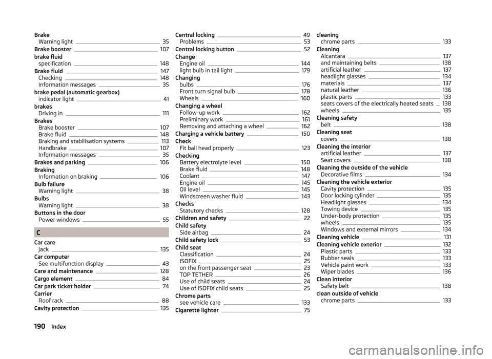
BrakeWarning light35
Brake booster107
brake fluid specification
148
Brake fluid147
Checking148
Information messages35
brake pedal (automatic gearbox) indicator light
41
brakes Driving in
111
Brakes Brake booster
107
Brake fluid148
Braking and stabilisation systems113
Handbrake107
Information messages35
Brakes and parking106
Braking Information on braking
106
Bulb failure Warning light
38
Bulbs Warning light
38
Buttons in the door Power windows
55
C
Car care Jack
135
Car computer See multifunction display
43
Care and maintenance128
Cargo element84
Car park ticket holder74
Carrier Roof rack
88
Cavity protection135
Central locking49
Problems53
Central locking button52
Change Engine oil
144
light bulb in tail light179
Changing bulbs
176
Front turn signal bulb178
Wheels160
Changing a wheel Follow-up work
162
Preliminary work161
Removing and attaching a wheel162
Charging a vehicle battery150
Check Fit ball head properly
123
Checking Battery electrolyte level
150
Brake fluid148
Coolant147
Engine oil145
Oil level145
Windscreen washer fluid143
Checks Statutory checks
128
Children and safety22
Child safety Side airbag
24
Child safety lock53
Child seat Classification
24
ISOFIX25
on the front passenger seat23
TOP TETHER26
Use of child seats24
Use of ISOFIX child seats25
Chrome parts see vehicle care
133
Cigarette lighter75
cleaning chrome parts133
Cleaning Alcantara
137
and maintaining belts138
artificial leather137
headlight glasses134
materials137
natural leather136
plastic parts133
seats covers of the electrically heated seats138
wheels135
Cleaning safety belt
138
Cleaning seat covers
138
Cleaning the interior artificial leather
137
Seat covers138
Cleaning the outside of the vehicle Decorative films
134
Cleaning the vehicle exterior Cavity protection
135
Door locking cylinder135
Headlight glasses134
Towing device135
Under-body protection135
wheels135
Windows and external mirrors134
Cleaning vehicle131
Cleaning vehicle exterior132
Plastic parts133
Rubber seals133
Vehicle paint work133
Wiper blades136
Clean interior Safety belt
138
clean outside of vehicle chrome parts
133
190Index