gearbox SKODA RAPID SPACEBACK 2014 1.G Owner's Manual
[x] Cancel search | Manufacturer: SKODA, Model Year: 2014, Model line: RAPID SPACEBACK, Model: SKODA RAPID SPACEBACK 2014 1.GPages: 204, PDF Size: 27.11 MB
Page 5 of 204
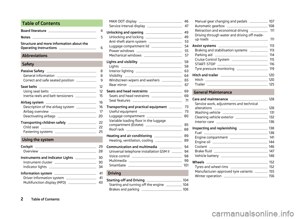
Table of Contents
Board literature4
Notes
5
Structure and more information about the
Operating Instructions
6
Abbreviations
Safety
Passive Safety
8
General information
8
Correct and safe seated position
9
Seat belts
12
Using seat belts
12
Inertia reels and belt tensioners
15
Airbag system
16
Description of the airbag system
16
Airbag overview
17
Deactivating airbags
20
Transporting children safely
22
Child seat
22
Fastening systems
25
Using the system
Cockpit
29
Overview
28
Instruments and Indicator Lights
30
Instrument cluster
30
Indicator lights
34
Information system
41
Driver information system
41
Multifunction display (MFD)
43MAXI DOT display46Service interval display47
Unlocking and opening
49
Unlocking and locking
49
Anti-theft alarm system
53
Luggage compartment lid
54
Power windows
55
Mechanical windows
57
Lights and visibility
58
Lights
58
Interior lighting
63
Visibility
64
Windscreen wipers and washers
65
Rear mirror
67
Seats and head restraints
69
Seats and head restraints
69
Seat features
71
Transporting and practical equipment
73
Useful equipment
73
Luggage compartment
80
Variable loading floor in the luggage
compartment (Estate)
85
Roof rack
88
Heating and air conditioning
89
Heating, ventilation, cooling
89
Communication and multimedia
94
Universal telephone installation GSM II
94
Voice control
98
Multimedia
99
SmartGate
101
Driving
Starting-off and Driving
104
Starting and turning off the engine
104
Brakes and parking
106Manual gear changing and pedals107Automatic gearbox108
Retraction and economical driving
111
Driving through water and driving off made-
up roads
111
Assist systems
113
Braking and stabilisation systems
113
Parking aid
114
Cruise Control System
115
START-STOP
116
Tyre pressure monitoring
119
Hitch and trailer
120
Hitch
120
Trailer
125
General Maintenance
Care and maintenance
128
Service work, adjustments and technical alterations
128
Washing vehicle
131
Cleaning vehicle exterior
132
Interior care
136
Inspecting and replenishing
138
Fuel
138
Engine compartment
141
Engine oil
144
Coolant
146
Brake fluid
147
Vehicle battery
148
Wheels
152
Tyres and wheel rims
152
Manufacturer-approved tyre variants
155
Winter operation
1562Table of Contents
Page 10 of 204
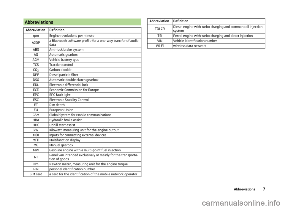
AbbreviationsAbbreviationDefinitionrpmEngine revolutions per minuteA2DPa Bluetooth software profile for a one-way transfer of audio
dataABSAnti-lock brake systemAGAutomatic gearboxAGMVehicle battery typeTCSTraction controlCO 2Carbon dioxideDPFDiesel particle filterDSGAutomatic double clutch gearboxEDLElectronic differential lockECEEconomic Commission for EuropeEPCEPC fault lightESCElectronic Stability ControlETRim depthEUEuropean UnionGSMGlobal System for Mobile communicationsHBAHydraulic brake assistHHCUphill start assistkWKilowatt, measuring unit for the engine outputMDIInputs for connecting external devicesMFDMultifunction displayMGManual gearboxMPIGasoline engine with a multi-point fuel injectionN1Panel van intended exclusively or mainly for the transporta-
tion of goodsNmNewton meter, measuring unit for the engine torquePINpersonal identification numberSIM carda card for the identification of the mobile network operatorAbbreviationDefinitionTDI CRDiesel engine with turbo charging and common rail injection
systemTSIPetrol engine with turbo charging and direct injectionVINVehicle identification numberWi-Fiwireless data network7Abbreviations
Page 32 of 204
Using the system
Cockpit
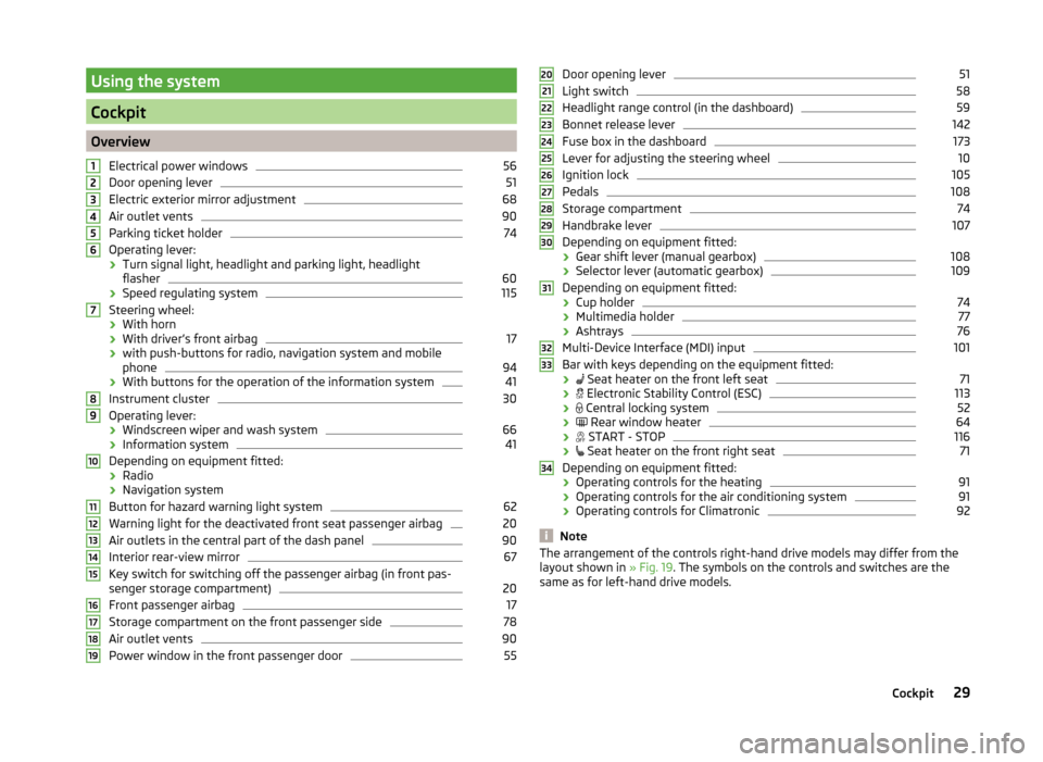
OverviewElectrical power windows
56
Door opening lever
51
Electric exterior mirror adjustment
68
Air outlet vents
90
Parking ticket holder
74
Operating lever:
› Turn signal light, headlight and parking light, headlight
flasher
60
› Speed regulating system
115
Steering wheel:
› With horn
› With driver’s front airbag
17
›with push-buttons for radio, navigation system and mobile
phone
94
› With buttons for the operation of the information system
41
Instrument cluster
30
Operating lever:
› Windscreen wiper and wash system
66
›Information system
41
Depending on equipment fitted:
› Radio
› Navigation system
Button for hazard warning light system
62
Warning light for the deactivated front seat passenger airbag
20
Air outlets in the central part of the dash panel
90
Interior rear-view mirror
67
Key switch for switching off the passenger airbag (in front pas-
senger storage compartment)
20
Front passenger airbag
17
Storage compartment on the front passenger side
78
Air outlet vents
90
Power window in the front passenger door
5512345678910111213141516171819Door opening lever51
Light switch
58
Headlight range control (in the dashboard)
59
Bonnet release lever
142
Fuse box in the dashboard
173
Lever for adjusting the steering wheel
10
Ignition lock
105
Pedals
108
Storage compartment
74
Handbrake lever
107
Depending on equipment fitted:
› Gear shift lever (manual gearbox)
108
›Selector lever (automatic gearbox)
109
Depending on equipment fitted:
› Cup holder
74
›Multimedia holder
77
›Ashtrays
76
Multi-Device Interface (MDI) input
101
Bar with keys depending on the equipment fitted:
›
Seat heater on the front left seat
71
›
Electronic Stability Control (ESC)
113
›
Central locking system
52
›
Rear window heater
64
›
START - STOP
116
›
Seat heater on the front right seat
71
Depending on equipment fitted:
› Operating controls for the heating
91
›
Operating controls for the air conditioning system
91
›Operating controls for Climatronic
92
Note
The arrangement of the controls right-hand drive models may differ from the
layout shown in » Fig. 19. The symbols on the controls and switches are the
same as for left-hand drive models.20212223242526272829303132333429Cockpit
Page 34 of 204
Speedometer » page 31
› with warning lights
» page 34
Button for display mode:
› Time settings
» page 33
› Enable/disable the display of the second speed 1)
» page 33
› Service intervals - Display of the number of days and kilometres remain-
ing until the next service 1)
» page 47
Button for: › Reset counter for distance travelled (trip)
» page 33
› Setting the time
› enable / disable the mode selected by means of the 4
key
Coolant temperature gauge 2)
» page 32
Fuel gauge 2)
» page 32
Revolution counter
Read and observe
on page 30 first.
The tachometer
1
» Fig. 20 on page 30 or » Fig. 21 on page 30 shows the ac-
tual engine speed per minute.
The beginning of the red scale range of the tachometer indicates the maxi-
mum permitted engine speed of a driven-in and operating warm engine.
You should shift into the next highest gear before the red scale of the revolu- tion counter is reached, or select mode D on the automatic gearbox.
The gear recommendation is important to note in order to maintain the opti-
mum engine speed » page 43.
CAUTION
The pointer of the tachometer must reach the red area for only a short time -
there is a risk of engine damage!34567DisplayFig. 22
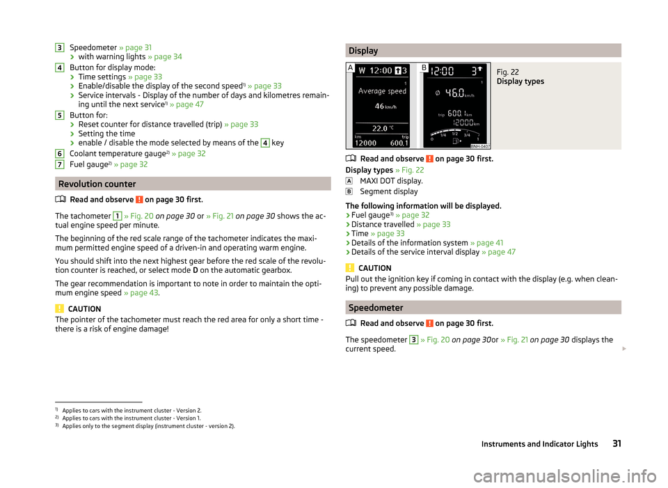
Display types
Read and observe on page 30 first.
Display types » Fig. 22
MAXI DOT display.
Segment display
The following information will be displayed.
› Fuel gauge 3)
» page 32
› Distance travelled
» page 33
› Time
» page 33
› Details of the information system
» page 41
› Details of the service interval display
» page 47
CAUTION
Pull out the ignition key if coming in contact with the display (e.g. when clean-
ing) to prevent any possible damage.
Speedometer
Read and observe
on page 30 first.
The speedometer
3
» Fig. 20 on page 30 or » Fig. 21 on page 30 displays the
current speed.
1)
Applies to cars with the instrument cluster - Version 2.
2)
Applies to cars with the instrument cluster - Version 1.
3)
Applies only to the segment display (instrument cluster - version 2).
31Instruments and Indicator Lights
Page 37 of 204
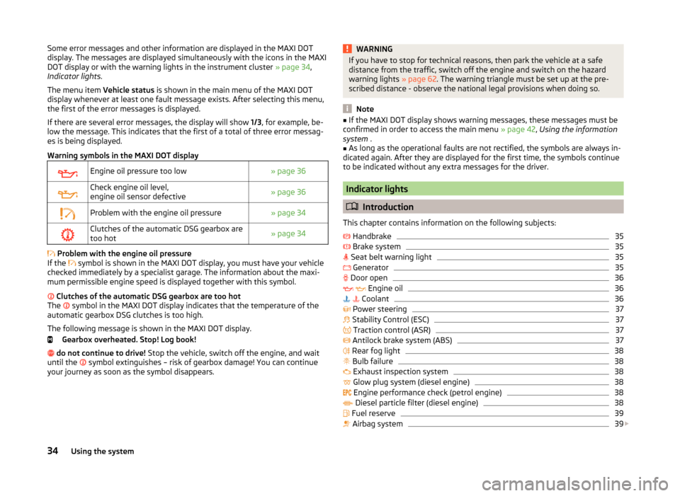
Some error messages and other information are displayed in the MAXI DOT
display. The messages are displayed simultaneously with the icons in the MAXI
DOT display or with the warning lights in the instrument cluster » page 34,
Indicator lights .
The menu item Vehicle status is shown in the main menu of the MAXI DOT
display whenever at least one fault message exists. After selecting this menu,
the first of the error messages is displayed.
If there are several error messages, the display will show 1/3, for example, be-
low the message. This indicates that the first of a total of three error messag-
es is being displayed.
Warning symbols in the MAXI DOT displayEngine oil pressure too low» page 36Check engine oil level,
engine oil sensor defective» page 36Problem with the engine oil pressure» page 34Clutches of the automatic DSG gearbox are
too hot» page 34
Problem with the engine oil pressure
If the symbol is shown in the MAXI DOT display, you must have your vehicle
checked immediately by a specialist garage. The information about the maxi-
mum permissible engine speed is displayed together with this symbol.
Clutches of the automatic DSG gearbox are too hot
The symbol in the MAXI DOT display indicates that the temperature of the
automatic gearbox DSG clutches is too high.
The following message is shown in the MAXI DOT display. Gearbox overheated. Stop! Log book!
do not continue to drive! Stop the vehicle, switch off the engine, and wait
until the symbol extinguishes – risk of gearbox damage! You can continue
your journey as soon as the symbol disappears.
WARNINGIf you have to stop for technical reasons, then park the vehicle at a safe
distance from the traffic, switch off the engine and switch on the hazard
warning lights » page 62. The warning triangle must be set up at the pre-
scribed distance - observe the national legal provisions when doing so.
Note
■ If the MAXI DOT display shows warning messages, these messages must be
confirmed in order to access the main menu » page 42, Using the information
system .■
As long as the operational faults are not rectified, the symbols are always in-
dicated again. After they are displayed for the first time, the symbols continue
to be indicated without any extra messages for the driver.
Indicator lights
Introduction
This chapter contains information on the following subjects:
Handbrake
35
Brake system
35
Seat belt warning light
35
Generator
35
Door open
36
Engine oil
36
Coolant
36
Power steering
37
Stability Control (ESC)
37
Traction control (ASR)
37
Antilock brake system (ABS)
37
Rear fog light
38
Bulb failure
38
Exhaust inspection system
38
Glow plug system (diesel engine)
38
Engine performance check (petrol engine)
38
Diesel particle filter (diesel engine)
38
Fuel reserve
39
Airbag system
39
34Using the system
Page 38 of 204
Tyre inflation pressure40 Windscreen washer fluid40
Turn signal system
40
Fog lights
40
Cruise control system
41
Brake pedal (automatic gearbox)
41
Main beam
41
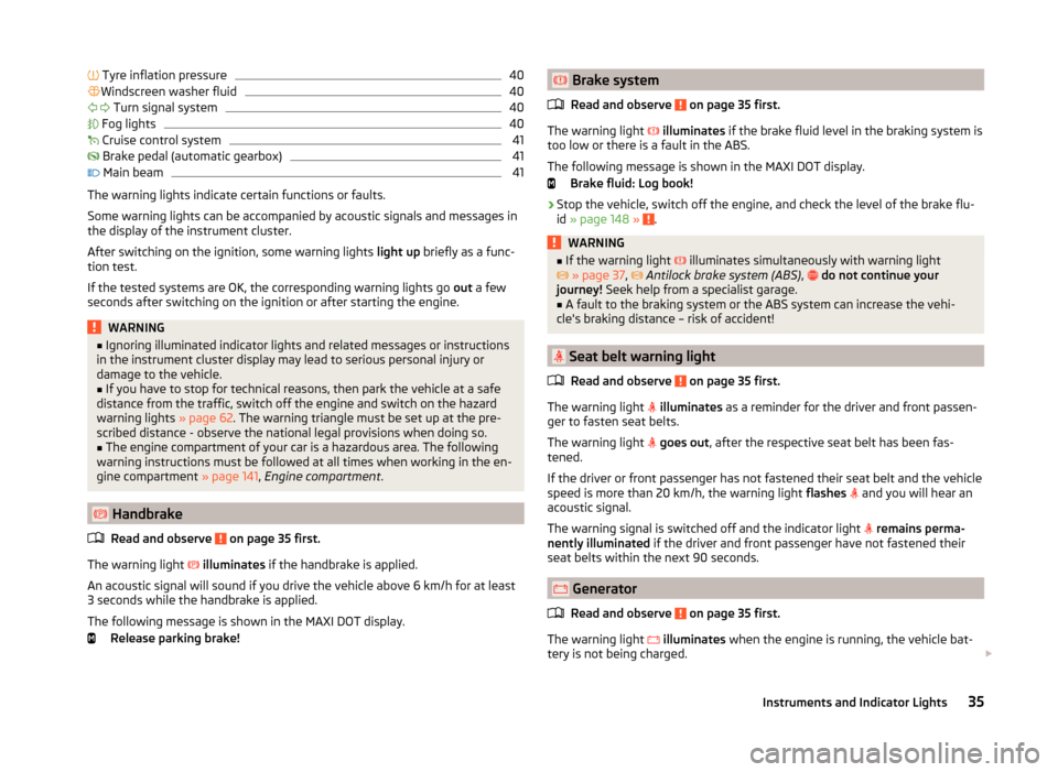
The warning lights indicate certain functions or faults.
Some warning lights can be accompanied by acoustic signals and messages in
the display of the instrument cluster.
After switching on the ignition, some warning lights light up briefly as a func-
tion test.
If the tested systems are OK, the corresponding warning lights go out a few
seconds after switching on the ignition or after starting the engine.
WARNING■ Ignoring illuminated indicator lights and related messages or instructions
in the instrument cluster display may lead to serious personal injury or
damage to the vehicle.■
If you have to stop for technical reasons, then park the vehicle at a safe
distance from the traffic, switch off the engine and switch on the hazard
warning lights » page 62. The warning triangle must be set up at the pre-
scribed distance - observe the national legal provisions when doing so.
■
The engine compartment of your car is a hazardous area. The following
warning instructions must be followed at all times when working in the en-
gine compartment » page 141, Engine compartment .
Handbrake
Read and observe
on page 35 first.
The warning light
illuminates if the handbrake is applied.
An acoustic signal will sound if you drive the vehicle above 6 km/h for at least
3 seconds while the handbrake is applied.
The following message is shown in the MAXI DOT display. Release parking brake!
Brake system
Read and observe
on page 35 first.
The warning light
illuminates if the brake fluid level in the braking system is
too low or there is a fault in the ABS.
The following message is shown in the MAXI DOT display. Brake fluid: Log book!
›
Stop the vehicle, switch off the engine, and check the level of the brake flu-
id » page 148 » .
WARNING■
If the warning light illuminates simultaneously with warning light
» page 37 , Antilock brake system (ABS) , do not continue your
journey! Seek help from a specialist garage.■
A fault to the braking system or the ABS system can increase the vehi-
cle's braking distance – risk of accident!
Seat belt warning light
Read and observe
on page 35 first.
The warning light
illuminates as a reminder for the driver and front passen-
ger to fasten seat belts.
The warning light
goes out , after the respective seat belt has been fas-
tened.
If the driver or front passenger has not fastened their seat belt and the vehicle
speed is more than 20 km/h, the warning light flashes
and you will hear an
acoustic signal.
The warning signal is switched off and the indicator light
remains perma-
nently illuminated if the driver and front passenger have not fastened their
seat belts within the next 90 seconds.
Generator
Read and observe
on page 35 first.
The warning light
illuminates when the engine is running, the vehicle bat-
tery is not being charged.
35Instruments and Indicator Lights
Page 44 of 204
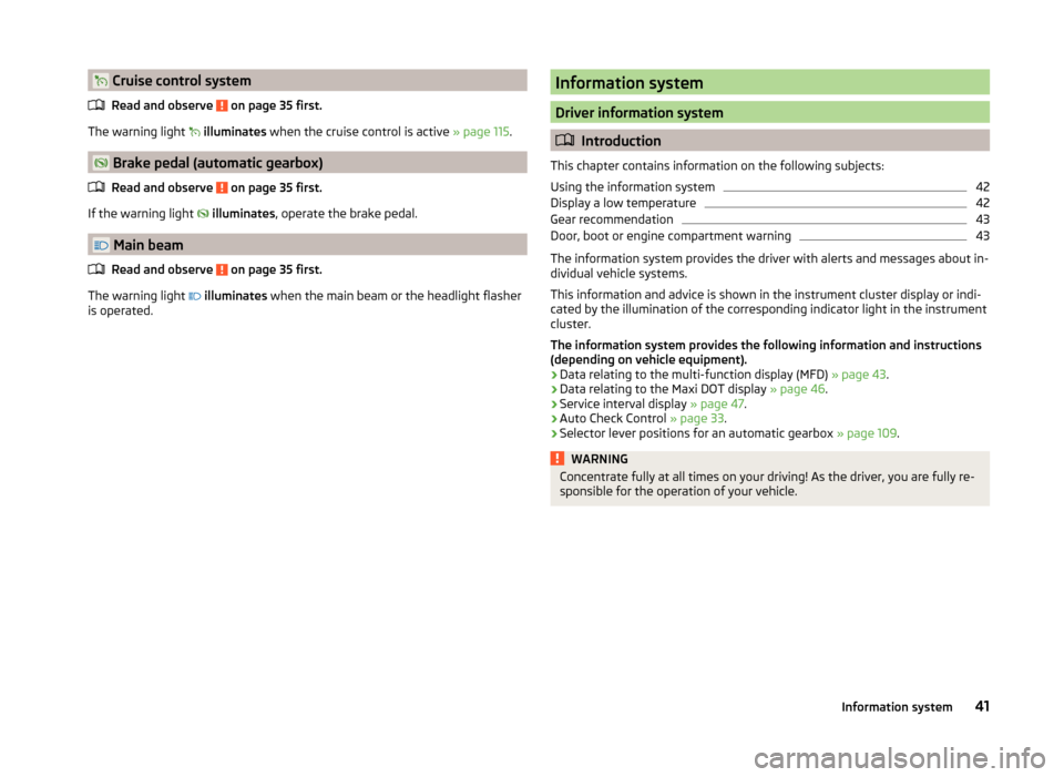
Cruise control systemRead and observe
on page 35 first.
The warning light
illuminates when the cruise control is active » page 115.
Brake pedal (automatic gearbox)
Read and observe
on page 35 first.
If the warning light
illuminates , operate the brake pedal.
Main beam
Read and observe
on page 35 first.
The warning light
illuminates when the main beam or the headlight flasher
is operated.
Information system
Driver information system
Introduction
This chapter contains information on the following subjects:
Using the information system
42
Display a low temperature
42
Gear recommendation
43
Door, boot or engine compartment warning
43
The information system provides the driver with alerts and messages about in-
dividual vehicle systems.
This information and advice is shown in the instrument cluster display or indi-
cated by the illumination of the corresponding indicator light in the instrument
cluster.
The information system provides the following information and instructions
(depending on vehicle equipment).
› Data relating to the multi-function display (MFD)
» page 43.
› Data relating to the Maxi DOT display
» page 46.
› Service interval display
» page 47.
› Auto Check Control
» page 33.
› Selector lever positions for an automatic gearbox
» page 109.
WARNINGConcentrate fully at all times on your driving! As the driver, you are fully re-
sponsible for the operation of your vehicle.41Information system
Page 46 of 204
Gear recommendationFig. 27
Information on the selected
gear / Gear recommendation
Read and observe on page 41 first.
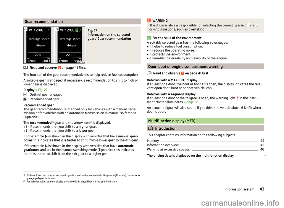
The function of the gear recommendation is to help reduce fuel consumption.
A suitable gear is engaged, if necessary, a recommendation to shift to high or
lower gear is displayed.
Display » Fig. 27
Optimal gear engaged
Recommended gear
Recommended gear
The gear recommendation is intended only for vehicles with a manual trans- mission or for vehicles with an automatic transmission in manual shift mode
(Tiptronic).
The recommended 1)
gear and the arrow icon 2)
is displayed.
›
- Recommends that you shift to a
higher gear.
›
- Recommends that you shift to a
lower gear
If for example is shown in the display with vehicles that have
manual gear-
boxes this indicates that it is better to shift from a lower gear to the 4th gear.
If for example is shown in the display with vehicles that have
automatic
gearboxes and are in the manual switching mode (Tiptronic), this indicates
that it is better to shift from the 4th gear to a higher gear.
WARNINGThe driver is always responsible for selecting the correct gear in different
driving situations, such as overtaking.
For the sake of the environment
A suitably selected gear has the following advantages.■It helps to reduce fuel consumption.■
It reduces the operating noise.
■
It protects the environment.
■
It benefits the durability and reliability of the engine.
Door, boot or engine compartment warning
Read and observe
on page 41 first.
Vehicles with a MAXI DOT display
If at least one door, the boot or bonnet is open, the display indicates the rele-
vant open door, boot or bonnet vehicle icon.
Vehicles with a segment display
If at least one door or the tailgate is open, the warning light
in the instru-
ment cluster illuminates » page 36.
An acoustic signal will also sound if you drive the vehicle above 6 km/h when a
door is open.
Multifunction display (MFD)
Introduction
This chapter contains information on the following subjects:
Memory
44
Information overview
45
Warning at excessive speeds
46
The driving data is displayed on the multifunction display.
1)
With vehicles that have an automatic gearbox and in the manual switching mode (Tiptronic) the
current-
ly engaged gear is shown.
2)
For vehicles with segment display the arrow is displayed behind the gear indication.
43Information system
Page 49 of 204
Warning at excessive speeds
Set the speed limit, e.g. for the maximum permissible speed in
towns » page 46 , Warning at excessive speeds .
Warning at excessive speeds
Read and observe
on page 44 first.
Adjust the speed limit while the vehicle is stationary
›
Select the menu item Speed warning (
) or
(
).
›
Activate the speed limit option by confirming this menu item 1)
.
›
Set the desired speed limit, e.g. 50 km/h.
›
Store the speed limit by confirming the set value, or wait several seconds;
your settings will be saved automatically.
The speed limit can be adjusted from 30 km/h to 250 km/h in 5 km/h incre-
ments.
Adjusting the speed limit while the vehicle is moving
›
Select the menu item Speed warning (
) or
(
).
›
Drive at the desired speed, e.g. 50 km/h.
›
Confirm the current speed as the speed limit.
If you wish to adjust the set speed limit, you can do so in 5 km/h intervals (e.g.
the accepted speed of 47 km/h increases to 50 km/h or decreases to 45 km/h).
›
Store the speed limit, or wait several seconds; your settings will be saved au-
tomatically.
Change or disable speed limit
›
Select the menu item Speed warning (
) or
(
).
›
By confirming the stored value, the speed limit is disabled.
›
By reconfirming, the option to change the speed limit is activated.
If the set speed limit is exceeded, an audible signal will sound as a warning.
The menu item Speed warning (MAXI DOT display) or
(Segment display) ap-
pears in the display at the same time as the set threshold.
The set speed limit value remains stored even after switching off the ignition.
MAXI DOT display
Introduction
This chapter contains information on the following subjects:
Main menu
46
Settings
47
Compass point display
47
The MAXI DOT display provides you with information about the current operat-
ing state of your vehicle. Depending on the vehicle equipment, it also provides
you with data relating to the radio, multifunction display (MFD), mobile phone,
navigation system, automatic gearbox » page 108 and devices connected via
the MDI input.
WARNINGConcentrate fully at all times on your driving! As the driver, you are fully re-
sponsible for the operation of your vehicle.
Main menu
Read and observe
on page 46 first.
Press and hold button
A
or
C
» Fig. 26 on page 42 to activate the MAIN
MENU . By briefly pressing the
C
button you will reach one level higher.
Main menu items (depending on vehicle equipment) ■ MFD (Multifunction display) » page 43
■ Audio » Operating instructions for the radio
■ Navigation » Operating instructions for the navigation system
■ Phone » page 94 ;
■ Vehicle status » page 33
■ Settings » page 47
The Audio and Navigation menu items are only displayed when the factory-fit-
ted radio or navigation system is switched on.
1)
If no value is set the output value 30 km/h is automatically displayed.
46Using the system
Page 108 of 204

Locking›Withdraw the ignition key.›
Turn the steering wheel to the left or right until the steering lock clicks into
place.
Unlocking
›
Insert the key into the ignition lock.
›
Switch on the ignition » page 105.
The steering lock is unlocked.
If the ignition switch cannot be turned on, then turn the steering wheel back and forth slightly and thereby unlock the steering lock.
Ignition on / off and start the engine
Fig. 99
Positions of the vehicle key in the ignition lock
Read and observe and on page 104 first.
Positions of the vehicle key in the ignition lock » Fig. 99
Ignition switched off, engine switched off
Ignition switched on
Starting engine
Switching ignition on/off
›
Turn key to position
2
.
The ignition is switched on.
›
Turn key to position
1
.
The ignition is switched off.
Procedure for starting the engine
›
Firmly apply the handbrake.
›
For vehicles with manual transmission , shift gear stick to neutral, depress
the clutch pedal and hold it there until the engine starts.
123› On vehicles with
automatic transmission , place the selector lever in position
P or N and depress the brake pedal until the engine starts.›
Turn the key into position
3
to the stop and release immediately after the
engine has been started – do not apply the accelerator.
After letting go, the vehicle key will return to position
2
.
For vehicles with diesel engines the glow plug warning light
goes on during
starting. The engine can be started after the indicator light goes out.
If the engine does not start within 10 seconds, turn the key to position
1
. Re-
peat the start-up process after approx. half a minute.
Vehicles with the START-STOP system and manual gearbox
The engine will not start if the clutch pedal is not depressed.
The following message is shown in the information cluster display. Depress clutch to start.
CLUTCH
Vehicles with the START-STOP system and automatic gearbox
The engine will not start if the brake pedal is not depressed.
The following message is shown in the information cluster display. Depress brake to start.
BRAKE
Note
■ The engine running noises may louder at first be louder for a short time after
starting the cold engine. This is quite normal and is not an operating problem.■
You should not switch on any major electrical components during the heat-
ing period otherwise the vehicle battery will be drained unnecessarily.
Switching off the engine
Read and observe
and on page 104 first.
›
Stop the vehicle » page 107, Parking .
›
Turn key to position
1
» Fig. 99 on page 105 .
The engine and the ignition are switched off simultaneously.
For vehicles with automatic transmission, the ignition key can only be removed if the selector lever is in position P .
105Starting-off and Driving