warning light SKODA RAPID SPACEBACK 2014 1.G Owner's Manual
[x] Cancel search | Manufacturer: SKODA, Model Year: 2014, Model line: RAPID SPACEBACK, Model: SKODA RAPID SPACEBACK 2014 1.GPages: 204, PDF Size: 27.11 MB
Page 11 of 204
Safety
Passive Safety
General information
Introduction
This chapter contains information on the following subjects:
Before setting off
8
Driving safety
8
Safety equipment
8
In this section you will find important information, tips and notes on the sub-
ject of passive safety in your vehicle.
We have combined everything here which you should be familiar with, for ex-
ample, regarding seat belts, airbags, child seats and safety of children.
WARNING■ This chapter contains important information on how to use the vehicle for
the driver and his occupants.■
You can find further information on safety concerning you and those trav-
elling with you in the following chapters of this owner's manual.
■
The complete on-board literature should always be in the vehicle. This
applies in particular, if you rent out or sell the vehicle.
Before setting off
Read and observe
on page 8 first.
For your own safety and the safety of the people travelling with you, please
pay attention to the following points before setting off.
Ensure that the lighting and the turn signal system are functioning proper-
ly.
Ensure that the function of the wipers and the condition of the wiper
blades are free of any defects.
Ensure that all of the windows offer good visibility to the outside.
Adjust the rear-view mirror so that vision to the rear is guaranteed.
Ensure that the mirrors are not covered.
Check the tyre inflation pressure.
Check the engine oil, brake fluid and coolant level.
Secure all items of luggage.
Do not exceed the permissible axle loads and permissible gross weight of
the vehicle.
Close all doors as well as the bonnet and boot lid.
Ensure that no objects can obstruct the pedals.
Protect children in suitable child seats with correctly fastened seat
belts » page 22 , Transporting children safely .
Adopt the correct seated position » page 9, Correct and safe seated
position . Tell your passengers to assume the correct seated position.
Driving safety
Read and observe
on page 8 first.
The driver is fully responsible for himself and his occupants. If your driving
safety is effected, you place yourself and the oncoming traffic at risk.
The following guidelines must therefore be observed. Do not become distracted from concentrating on the traffic situation, e.g.
by your passengers or mobile phone calls.
Never drive when your driving ability is impaired, e.g. due to medication, al-
cohol or drugs.
Keep to the traffic regulations and the permissible speed limit.
Always adjust the driving speed to the road, traffic and weather condi-
tions.
Take regular breaks on long journeys – at least every two hours.
Safety equipment
Read and observe
on page 8 first.
The following list contains only part of the safety equipment in your vehicle.
› Three-point seat belts for all the seats.
› Belt force limiters for the front seats.
› Belt tensioners for the front seats.
› Seat belt height adjusters for the front seats.
› Front airbag for the driver and the front passenger.
› Side airbags.
› Head airbags.
› Anchoring points for child seats using the ISOFIX system.
8Safety
Page 12 of 204
›Anchoring points for child seats using the TOP TETHER system.
› Head restraints adjustable for height 1)
.
› Adjustable steering column.
The specified safety equipment works together, in order to optimally protect
you and those travelling with you in accident situations.
The safety equipment does not protect you or the people travelling with you, if
you or your occupants adopt an incorrect seated position or the equipment is
not correctly adjusted or used.
If the seat belt is not fastened properly, this may result in injuries if an airbag is
activated in the event of an accident.
Correct and safe seated position
Introduction
This chapter contains information on the following subjects:
Correct seated position for the driver
9
Adjusting the steering wheel position
10
Correct seated position for the front passenger
10
Correct seated position for the passengers in the rear seats
11
Examples of incorrect seated positions
11WARNING■ The front seats and all head restraints must be adjusted to match the
body size at all times and the seat belt must always be fastened properly to
provide the most effective levels of protection to the passengers.■
Each occupant must correctly fasten the seat belt belonging to the seat.
Children must be fastened » page 22, Transporting children safely with a
suitable restraint system.
■
If the occupant adopts an incorrect seated position, he is exposed to life-
threatening injuries, in case he is hit by a deployed airbag.
■
If the occupants on the rear seats are not sitting upright, the risk of injury
is increased due to incorrect routing of the seat belt.
■
The seat backrests must not be tilted too far back when driving, as this
will impair the function of the seat belts and of the airbag system – risk of
injury!
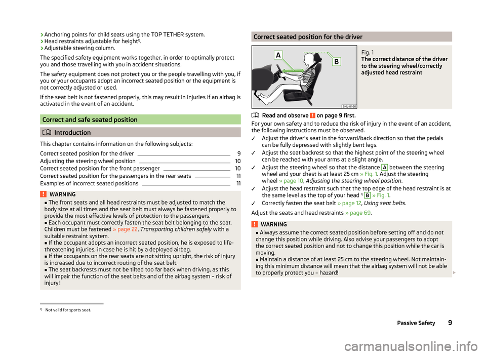
Correct seated position for the driverFig. 1
The correct distance of the driver
to the steering wheel/correctly
adjusted head restraint
Read and observe on page 9 first.
For your own safety and to reduce the risk of injury in the event of an accident, the following instructions must be observed.
Adjust the driver’s seat in the forward/back direction so that the pedals
can be fully depressed with slightly bent legs.
Adjust the seat backrest so that the highest point of the steering wheel
can be reached with your arms at a slight angle.
Adjust the steering wheel so that the distance
A
between the steering
wheel and your chest is at least 25 cm » Fig. 1. Adjust the steering
wheel » page 10 , Adjusting the steering wheel position .
Adjust the head restraint such that the top edge of the head restraint is at
the same level as the top of your head 1)
B
» Fig. 1 .
Correctly fasten the seat belt » page 12, Using seat belts .
Adjust the seats and head restraints » page 69.
WARNING■
Always assume the correct seated position before setting off and do not
change this position while driving. Also advise your passengers to adopt
the correct seated position and not to change this position while the car is
moving.■
Maintain a distance of at least 25 cm to the steering wheel. Not maintain-
ing this minimum distance will mean that the airbag system will not be able
to properly protect you – hazard!
1)
Not valid for sports seat.
9Passive Safety
Page 19 of 204
Airbag system
Description of the airbag system
Introduction
This chapter contains information on the following subjects:
System description
16
Airbag deployment
16WARNING■ An airbag can only offer you optimal protection in combination with a
fastened seat belt .■
The airbag is not a substitute for the seat belt, but instead forms part of
the complete passive vehicle safety concept.
■
To ensure passengers are protected with the greatest possible effect
when the airbag is deployed, the front seats must be correctly adjusted to
match the body size » page 9, Correct and safe seated position .
■
If you do not fasten the seat belts when driving, lean too far forward or
adopt an incorrect seated position, you are exposing yourself to increased
risk of injury in the event of an accident.
WARNINGInformation on the use of the airbag system■If there is a fault, the airbag system must be checked by a specialist ga-
rage immediately. Otherwise, there is a risk of the airbag not being activa-
ted in the event of an accident.■
No modifications of any kind may be made to parts of the airbag system.
■
Any work on the airbag system, including the installation and removal of
system components due to other repair work (e.g. removal of the steering
wheel), must only be carried out by a specialist garage.
■
Never make any changes to the front bumper or the bodywork.
■
It is prohibited to manipulate individual parts of the airbag system, as this
might result in the airbag being deployed.
■
The protective function of the airbag system is sufficient for only one ac-
cident. The airbag system must then be replaced if the airbag has been de-
ployed.
System description
Read and observe
on page 16 first.
The functional status of the airbag system is indicated by the indicator light
in the instrument cluster » page 39.
When the airbags are deployed, they fill with gas and inflate.
A grey white or red, non-harmful gas is released when the airbag is inflated.
This is perfectly normal and is not an indication of a fire in the vehicle.
Depending on the vehicle equipment, the airbag system consists of the
following modules.
› Electronic control unit.
› Front airbag for the driver and the front passenger
» page 17.
› Side airbags
» page 18.
› Head airbags
» page 19.
› Airbag warning light in the instrument cluster
» page 39.
› Key switch for the front passenger airbag
» page 20.
› Warning light for the front passenger airbag deactivation/activation in the
middle of the dash panel » page 20.
Note
■
The airbag system needs no maintenance during its working life.■If you sell your vehicle, provide the complete vehicle documentation to the
new owner. Please note that the information relating to the possibility of de-
activating the front passenger airbag must be included!■
When disposing of vehicle or parts of the airbag system, it is important to
comply with the national legal requirements.
Airbag deployment
Read and observe
on page 16 first.
The airbags inflate in fractions of a second and at a high speed in order to beable to offer additional protection in the event of an accident.
The airbag system is only functional when the ignition is switched on.
In certain accident situations, the several airbags may be deployed simultane-
ously.
The airbags are not deployed in the case of minor frontal and side collisions,
rear-end collisions, tilting of the vehicle and vehicle rollover.
16Safety
Page 20 of 204
Deployment factors
It is not possible to generally determine which deployment conditions apply to
the airbag system in every situation. An important role is played by factors
such as the type of object that the vehicle hits (hard/soft), the impact angle,
vehicle speed etc.
A decisive factor for the deployment of the airbags is the deceleration which
occurs. The control unit analyses the nature of the collision and activates the
relevant restraint system.
If the vehicle deceleration which occurs and is measured during the collision
remains below the prescribed reference values specified in the control unit,
the airbags are not deployed although the vehicle may well suffer severe dam-
age to the bodywork as a consequence of the accident.
The following airbags will be deployed in the event of a severe frontal
collision.
› Driver’s front airbag.
› Front passenger airbag.
The following airbags will be deployed in the event of a severe side collision.
› Front side airbag on the side of the accident.
› Head airbags on the side of the accident.
When an airbag is deployed, the following events occur.
› The interior lighting illuminates (if the switch for the interior light is in the
door contact position).
› The hazard warning lights are switched on.
› All the doors are unlocked.
› The fuel supply to the engine is interrupted.
Airbag overview
Introduction
This chapter contains information on the following subjects:
Front airbags
17
Side airbags
18
Head airbags
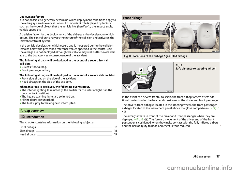
19Front airbagsFig. 8
Locations of the airbags / gas filled airbags
Fig. 9
Safe distance to steering wheel
In the event of a severe frontal collision, the front airbag system offers addi-
tional protection for the head and chest area of the driver and front passenger.
The driver's front airbag is located in the steering wheel, the front passenger
airbag is located in the instrument panel above the glove compartment » Fig. 8
- .
The airbags inflate in front of the driver and front passenger when they are
deployed » Fig. 8 -
. The forward movement of the driver and of the front
passenger is cushioned when they make contact with the fully inflated airbag
and the risk of injury to head and chest is thus reduced.
17Airbag system
Page 22 of 204
WARNING (Continued)■There must not be any further persons, animals or objects positioned be-
tween the occupants and the deployment area of the airbag. No accesso-
ries, such as cup holders, should be attached to the doors.■
If children adopt an incorrect seated position when travelling, they may
be exposed to an increased risk of injury in the event of an accident. This
can result in serious injuries » page 22, Child seat .
WARNING■
Only hang light items of clothing on the hooks fitted in the vehicle. Never
leave any heavy or sharp-edged objects in the pockets of the items of
clothing.■
Ensure that there are no excessive forces, such as violent knocks, kicks
etc., impact on the backrests of the seats otherwise the system may be
damaged. The side airbags would not be deployed in such a case!
■
Any seat or protective covers which you fit to the driver or front passen-
ger seats must only be of the type expressly authorized by ŠKODA. In view
of the fact that the airbag inflates out of the backrest of the seat, use of
non-approved seat or protective covers would considerably impair the pro-
tective function of the side airbag.
■
Any damage to the original seat covers in the area of the side airbag mod-
ule must be repaired immediately by a specialist garage.
■
The airbag modules in the front seats must not display any damage,
cracks or deep scratches. It is not permissible to use force in order to open
the modules.
Note
In vehicles with side airbags a label with the lettering is located on the
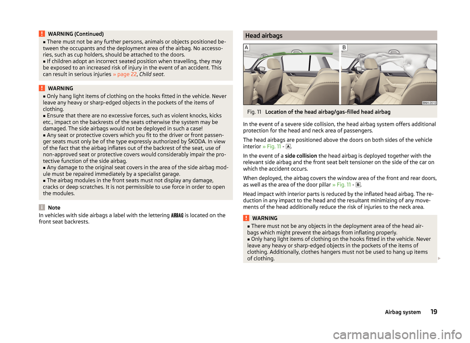
front seat backrests.Head airbagsFig. 11
Location of the head airbag/gas-filled head airbag
In the event of a severe side collision, the head airbag system offers additional protection for the head and neck area of passengers.
The head airbags are positioned above the doors on both sides of the vehicle
interior » Fig. 11 -
.
In the event of a side collision the head airbag is deployed together with the
relevant side airbag and the front seat belt tensioner on the side of the car on
which the accident occurs.
When deployed, the airbag covers the window area of the front and rear doors,
as well as the area of the door pillar » Fig. 11 -
.
Head impact with interior parts is reduced by the inflated head airbag. The re-
duction in any impact to the head and the resultant minimizing of any move-
ments of the head additionally reduce the risk of injuries to the neck area.
WARNING■ There must not be any objects in the deployment area of the head air-
bags which might prevent the airbags from inflating properly.■
Only hang light items of clothing on the hooks fitted in the vehicle. Never
leave any heavy or sharp-edged objects in the pockets of the items of
clothing. Additionally, clothes hangers must not be used to hang up items
of clothing.
19Airbag system
Page 23 of 204
WARNING (Continued)■The installation of impermissible accessories in the vicinity of the head
airbags can considerably impair the protection offered by the head airbag in
the event of it being deployed. When the deployed head airbag is inflated,
parts of the accessories fitted could be thrown into the interior of the car
and injure the occupants » page 128.■
The sun visors must not be swivelled towards the side windows in the
deployment area of the head airbags if any objects, such as ball-point pens,
etc. are attached to them. This might result in injuries to the occupants if
the head airbag is deployed.
■
There must not be any further persons, animals or objects positioned be-
tween the seated occupants and the deployment area of the airbag. In ad-
dition, none of the occupants should lean their head out of the window
when driving, or extend their arms and hands out of the window.
Note
In vehicles with head airbags, the lettering can be seen on the B column
cladding.
Deactivating airbags
Introduction
This chapter contains information on the following subjects:
Deactivating airbags
20
Deactivating the front passenger airbag
20
Deactivating airbags
Deactivating an airbag should be considered in cases such as the ones below. › If using a rear-facing child seat on the front passenger seat (due to different
legal regulations, the airbag must be deactivated if using a forwards-facing
child seat in some countries) » page 22, Transporting children safely .
› If it is not possible to maintain a distance of at least 25 cm between the mid-
dle of the steering wheel and chest, despite the driver's seat being correctly
adjusted.
› If special attachments are required in the area of the steering wheel because
of a physical disability.
› If different seats have been fitted (e.g. orthopaedic seats without side air-
bags).
The front passenger airbag can be switched off with the key-operated
switch » page 20 .
We recommend that you ask a ŠKODA service partner to deactivate any other airbags.
Monitoring the airbag system
The operational capability of the airbag system is monitored electronically, in-
cluding when one of the airbags is switched off.
Airbag deactivated using diagnostic equipment › The warning light
illuminates for approximately 4 seconds after the igni-
tion is switched on and then flashes again for approximately 12 seconds.
Front passenger airbag deactivated using the key switch in the storage com-
partment
› The warning light
lights up for approximately 3 seconds after the ignition
is switched on.
› The warning light
» Fig. 12 on page 20 -
comes on after the ignition
has been switched on.
Note
■ The national regulations for switching off airbags must be observed.■A ŠKODA service partner will be able to inform you which, if any, of your vehi-
cle's airbags can or must be deactivated.
Deactivating the front passenger airbag
Fig. 12
Key-operated switch for the front passenger airbag / warning
light for front seat passenger airbag deactivation
Only the front passenger airbag is deactivated with the key switch.
20Safety
Page 24 of 204
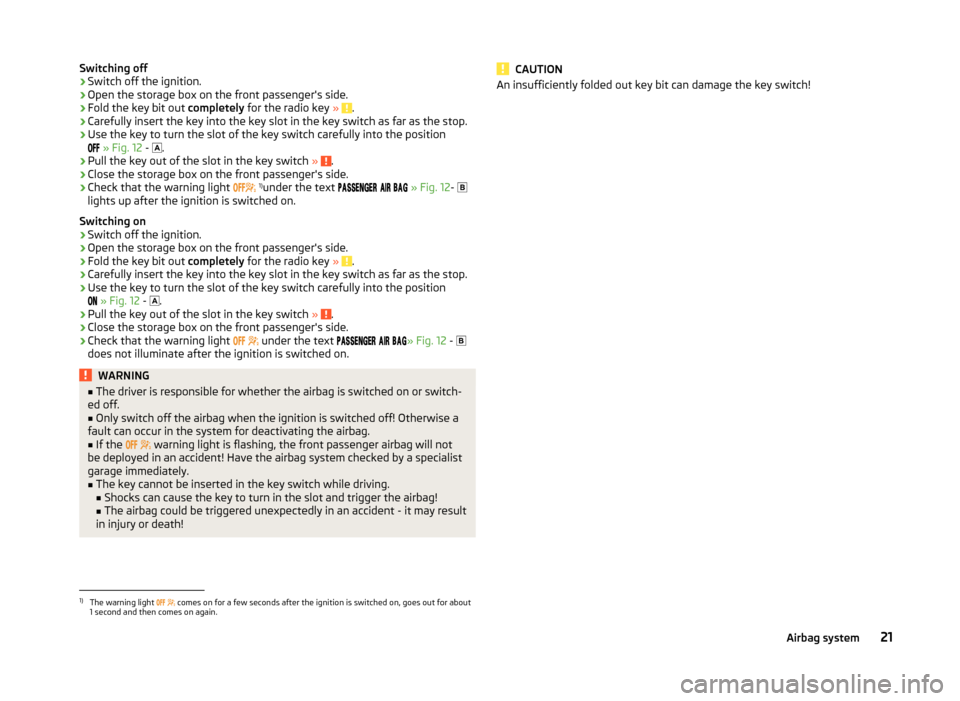
Switching off›Switch off the ignition.›
Open the storage box on the front passenger's side.
›
Fold the key bit out completely for the radio key » .
›
Carefully insert the key into the key slot in the key switch as far as the stop.
›
Use the key to turn the slot of the key switch carefully into the position
» Fig. 12 -
.
›
Pull the key out of the slot in the key switch » .
›
Close the storage box on the front passenger's side.
›
Check that the warning light
1)
under the text
» Fig. 12 -
lights up after the ignition is switched on.
Switching on
›
Switch off the ignition.
›
Open the storage box on the front passenger's side.
›
Fold the key bit out completely for the radio key » .
›
Carefully insert the key into the key slot in the key switch as far as the stop.
›
Use the key to turn the slot of the key switch carefully into the position
» Fig. 12 -
.
›
Pull the key out of the slot in the key switch
» .
›
Close the storage box on the front passenger's side.
›
Check that the warning light
under the text
» Fig. 12
-
does not illuminate after the ignition is switched on.
WARNING■ The driver is responsible for whether the airbag is switched on or switch-
ed off.■
Only switch off the airbag when the ignition is switched off! Otherwise a
fault can occur in the system for deactivating the airbag.
■
If the
warning light is flashing, the front passenger airbag will not
be deployed in an accident! Have the airbag system checked by a specialist
garage immediately.
■
The key cannot be inserted in the key switch while driving.
■ Shocks can cause the key to turn in the slot and trigger the airbag!
■ The airbag could be triggered unexpectedly in an accident - it may result
in injury or death!
CAUTIONAn insufficiently folded out key bit can damage the key switch!1)
The warning light comes on for a few seconds after the ignition is switched on, goes out for about
1 second and then comes on again.
21Airbag system
Page 32 of 204
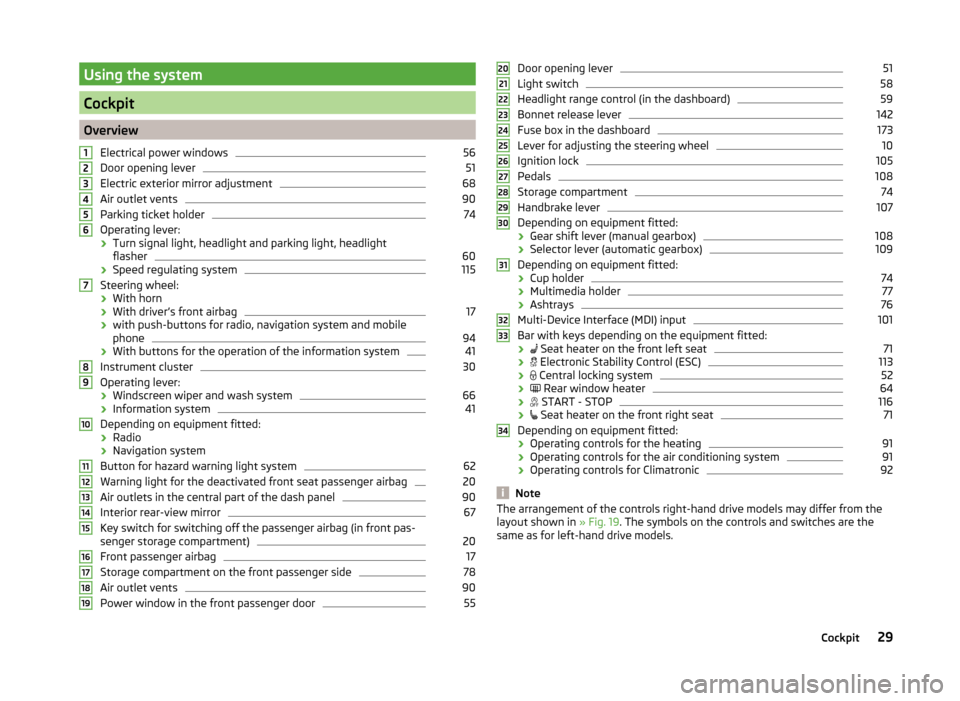
Using the system
Cockpit
OverviewElectrical power windows
56
Door opening lever
51
Electric exterior mirror adjustment
68
Air outlet vents
90
Parking ticket holder
74
Operating lever:
› Turn signal light, headlight and parking light, headlight
flasher
60
› Speed regulating system
115
Steering wheel:
› With horn
› With driver’s front airbag
17
›with push-buttons for radio, navigation system and mobile
phone
94
› With buttons for the operation of the information system
41
Instrument cluster
30
Operating lever:
› Windscreen wiper and wash system
66
›Information system
41
Depending on equipment fitted:
› Radio
› Navigation system
Button for hazard warning light system
62
Warning light for the deactivated front seat passenger airbag
20
Air outlets in the central part of the dash panel
90
Interior rear-view mirror
67
Key switch for switching off the passenger airbag (in front pas-
senger storage compartment)
20
Front passenger airbag
17
Storage compartment on the front passenger side
78
Air outlet vents
90
Power window in the front passenger door
5512345678910111213141516171819Door opening lever51
Light switch
58
Headlight range control (in the dashboard)
59
Bonnet release lever
142
Fuse box in the dashboard
173
Lever for adjusting the steering wheel
10
Ignition lock
105
Pedals
108
Storage compartment
74
Handbrake lever
107
Depending on equipment fitted:
› Gear shift lever (manual gearbox)
108
›Selector lever (automatic gearbox)
109
Depending on equipment fitted:
› Cup holder
74
›Multimedia holder
77
›Ashtrays
76
Multi-Device Interface (MDI) input
101
Bar with keys depending on the equipment fitted:
›
Seat heater on the front left seat
71
›
Electronic Stability Control (ESC)
113
›
Central locking system
52
›
Rear window heater
64
›
START - STOP
116
›
Seat heater on the front right seat
71
Depending on equipment fitted:
› Operating controls for the heating
91
›
Operating controls for the air conditioning system
91
›Operating controls for Climatronic
92
Note
The arrangement of the controls right-hand drive models may differ from the
layout shown in » Fig. 19. The symbols on the controls and switches are the
same as for left-hand drive models.20212223242526272829303132333429Cockpit
Page 33 of 204
Instruments and Indicator Lights
Instrument cluster
Introduction
This chapter contains information on the following subjects:
Overview
30
Revolution counter
31
Display
31
Speedometer
31
Coolant temperature gauge
32
Fuel gauge
32
Counter for distance driven
33
33
Display of the second speed
33
Auto Check Control
33
The instrument cluster gives the driver basic information such as the current
speed, engine speed, the state of some vehicle systems and the like.
Fault display
If there is a fault in the instrument cluster, the Error message will appear in
the display.
Seek help from a specialist garage.
WARNINGConcentrate fully at all times on your driving! As the driver you are fully re-
sponsible for road safety.
Note
When the ignition is on, the instrument cluster is illuminated 1)
. The brightness
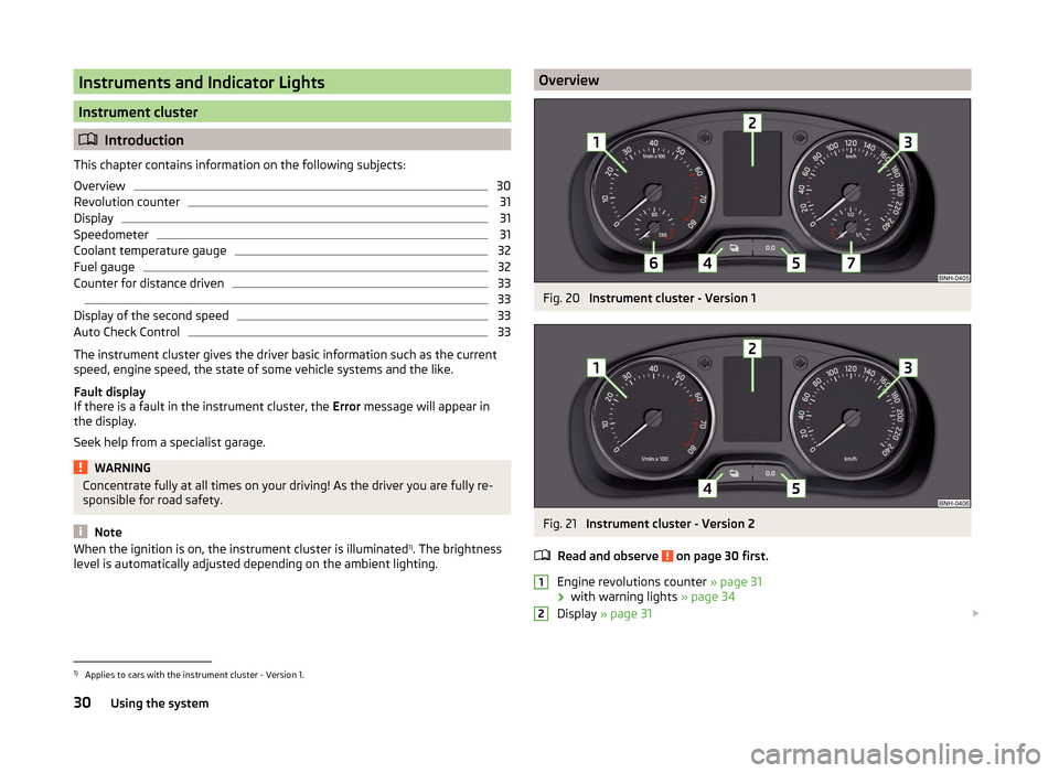
level is automatically adjusted depending on the ambient lighting.OverviewFig. 20
Instrument cluster - Version 1
Fig. 21
Instrument cluster - Version 2
Read and observe
on page 30 first.
Engine revolutions counter » page 31
› with warning lights
» page 34
Display » page 31
121)
Applies to cars with the instrument cluster - Version 1.
30Using the system
Page 34 of 204
Speedometer » page 31
› with warning lights
» page 34
Button for display mode:
› Time settings
» page 33
› Enable/disable the display of the second speed 1)
» page 33
› Service intervals - Display of the number of days and kilometres remain-
ing until the next service 1)
» page 47
Button for: › Reset counter for distance travelled (trip)
» page 33
› Setting the time
› enable / disable the mode selected by means of the 4
key
Coolant temperature gauge 2)
» page 32
Fuel gauge 2)
» page 32
Revolution counter
Read and observe
on page 30 first.
The tachometer
1
» Fig. 20 on page 30 or » Fig. 21 on page 30 shows the ac-
tual engine speed per minute.
The beginning of the red scale range of the tachometer indicates the maxi-
mum permitted engine speed of a driven-in and operating warm engine.
You should shift into the next highest gear before the red scale of the revolu- tion counter is reached, or select mode D on the automatic gearbox.
The gear recommendation is important to note in order to maintain the opti-
mum engine speed » page 43.
CAUTION
The pointer of the tachometer must reach the red area for only a short time -
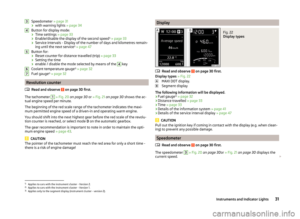
there is a risk of engine damage!34567DisplayFig. 22
Display types
Read and observe on page 30 first.
Display types » Fig. 22
MAXI DOT display.
Segment display
The following information will be displayed.
› Fuel gauge 3)
» page 32
› Distance travelled
» page 33
› Time
» page 33
› Details of the information system
» page 41
› Details of the service interval display
» page 47
CAUTION
Pull out the ignition key if coming in contact with the display (e.g. when clean-
ing) to prevent any possible damage.
Speedometer
Read and observe
on page 30 first.
The speedometer
3
» Fig. 20 on page 30 or » Fig. 21 on page 30 displays the
current speed.
1)
Applies to cars with the instrument cluster - Version 2.
2)
Applies to cars with the instrument cluster - Version 1.
3)
Applies only to the segment display (instrument cluster - version 2).
31Instruments and Indicator Lights