warning light SKODA RAPID SPACEBACK 2015 1.G Workshop Manual
[x] Cancel search | Manufacturer: SKODA, Model Year: 2015, Model line: RAPID SPACEBACK, Model: SKODA RAPID SPACEBACK 2015 1.GPages: 208, PDF Size: 29.2 MB
Page 118 of 208
NoteDuring control, speed can be increased by pressing the accelerator pedal. Re-
leasing the accelerator pedal will cause the speed to drop again to the set
speed.
Front Assist
Introduction
This chapter contains information on the following subjects:
Radar sensor
116
Operation
117
Distance warning (dangerous distance)
117
Warning and automatic braking
117
Disable/enable
118
Information messages
118
The Front Assist (hereinafter referred to as the system) warns you of the dan-
ger of a collision with a vehicle or another obstacle in front of the vehicle, and
tries to avoid a collision or mitigate its consequences by automatically applying
the brakes where necessary.
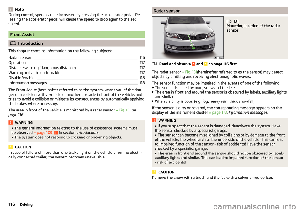
The area in front of the vehicle is monitored by a radar sensor » Fig. 131 on
page 116 .
WARNING■
The general information relating to the use of assistance systems must
be observed » page 109, in section Introduction .■
The system does not respond to crossing or oncoming objects.
CAUTION
In case of failure of more than one brake light on the vehicle or on the electri-
cally connected trailer, the system becomes unavailable.Radar sensorFig. 131
Mounting location of the radar
sensor
Read and observe and on page 116 first.
The radar sensor » Fig. 131(hereinafter referred to as the sensor) may detect
objects by emitting and receiving electromagnetic waves.
The sensor function may be impaired in the events of one of the following. ▶ The sensor is soiled by mud, snow and the like.
▶ The area in front and around the sensor is obscured by labels, auxiliary lights
and similar.
▶ When visibility is poor, (e.g. fog, heavy rain, thick snowfall).
If the sensor is dirty or covered, the corresponding message appears on the
display of the instrument cluster » page 118, Information messages .
WARNING■
If you suspect that the sensor is damaged, deactivate the system. Have
the sensor checked by a specialist garage.■
The sensor can become misaligned by collisions or by damage to the front
of the vehicle, the wheel arch or the underside of the vehicle. This can lead
to impaired function of the sensor - risk of accidents! Have the sensor
checked by a specialist garage.
■
The area in front and around the sensor should not be obscured by labels,
auxiliary lights and similar. This can lead to impaired function of the sensor
- risk of accidents!
CAUTION
Remove the snow with a brush and the ice with a solvent-free de-icer.116Driving
Page 122 of 208
The tyre pressure monitoring function (hereinafter referred to as the system)
monitors the tyre pressure while driving.
When changing the tyre inflation pressure, the warning light illuminates
in
the instrument cluster and an audible signal is heard.
Information on the procedure for the notification of change of tyre inflation pressure » page 34 .
The system can only function properly if the tyres have the prescribed inflation
pressure and this pressure values are stored in the system.WARNING■ The general information relating to the use of assistance systems must
be observed » page 109, in section Introduction .■
Having the correct tyre inflation pressure is always the driver's responsi-
bility. Tyre pressure should be checked regularly » page 155.
■
The system cannot warn in case of very rapid tyre inflation pressure loss,
e.g. in case of sudden tyre damage.
Save tyre pressure values
Read and observe
on page 120 first.
The tyre pressure values are always stored in the system, if one of the follow-
ing events occurs.
▶ Change of tyre inflation pressure.
▶ Change one or more wheels.
▶ Change in position of a wheel on the vehicle.
▶ The warning light in the instrument cluster.
The storage of the tyre pressure values depends on equipment, either in the
infotainment or by pressing a button.
WARNINGBefore storing the pressures, the tyres must be inflated to the specified in-
flation pressure » page 155. When storing incorrect pressure values, the
system could possibly not issue any warnings, even with a too low tyre
pressure.
CAUTION
The tyre pressure values are to be saved every 10,000 km or once annually to
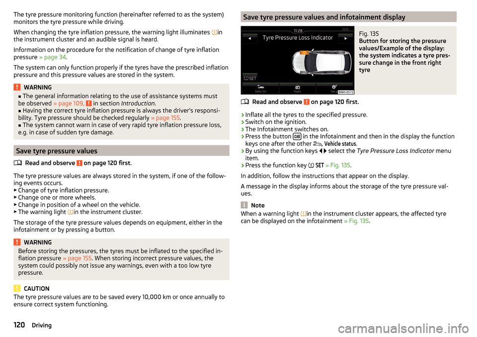
ensure correct system functioning.Save tyre pressure values and infotainment displayFig. 135
Button for storing the pressure
values/Example of the display:
the system indicates a tyre pres-
sure change in the front right
tyre
Read and observe on page 120 first.
›
Inflate all the tyres to the specified pressure.
›
Switch on the ignition.
›
The Infotainment switches on.
›
Press the button in the Infotainment and then in the display the function
keys one after the other ,
Vehicle status
.
›
By using the function keys
select the
Tyre Pressure Loss Indicator menu
item.
›
Press the function key
SET
» Fig. 135
.
In addition, follow the instructions that appear on the display.
A message in the display informs about the storage of the tyre pressure val-
ues.
Note
When a warning light in the instrument cluster appears, the affected tyre
can be displayed on the infotainment » Fig. 135.120Driving
Page 123 of 208
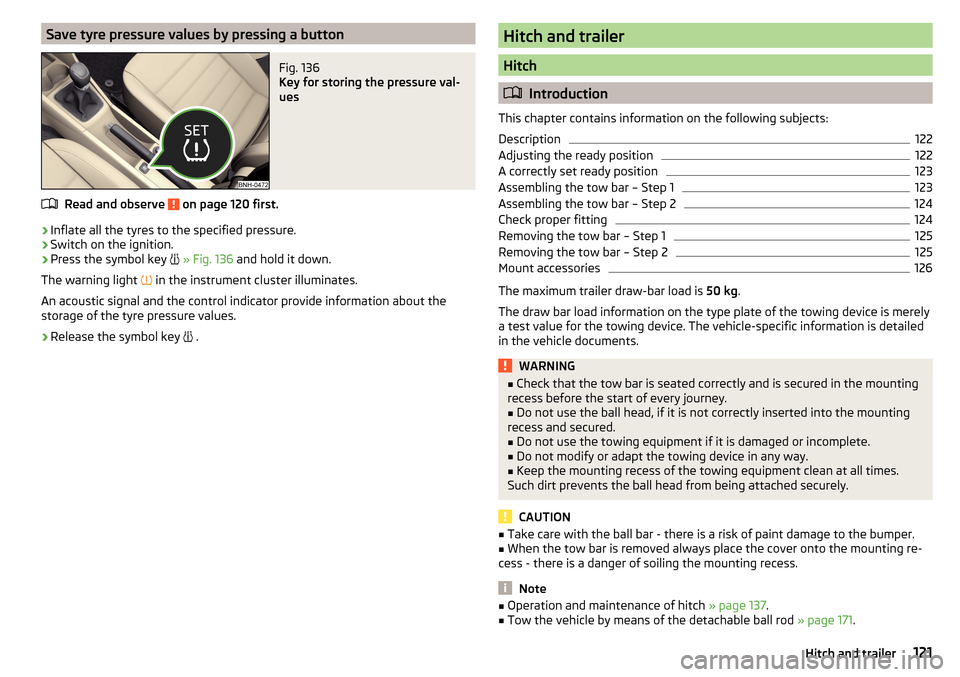
Save tyre pressure values by pressing a buttonFig. 136
Key for storing the pressure val-
ues
Read and observe on page 120 first.
›
Inflate all the tyres to the specified pressure.
›
Switch on the ignition.
›
Press the symbol key
» Fig. 136 and hold it down.
The warning light in the instrument cluster illuminates.
An acoustic signal and the control indicator provide information about the
storage of the tyre pressure values.
›
Release the symbol key .
Hitch and trailer
Hitch
Introduction
This chapter contains information on the following subjects:
Description
122
Adjusting the ready position
122
A correctly set ready position
123
Assembling the tow bar – Step 1
123
Assembling the tow bar – Step 2
124
Check proper fitting
124
Removing the tow bar – Step 1
125
Removing the tow bar – Step 2
125
Mount accessories
126
The maximum trailer draw-bar load is 50 kg.
The draw bar load information on the type plate of the towing device is merely
a test value for the towing device. The vehicle-specific information is detailed
in the vehicle documents.
WARNING■ Check that the tow bar is seated correctly and is secured in the mounting
recess before the start of every journey.■
Do not use the ball head, if it is not correctly inserted into the mounting
recess and secured.
■
Do not use the towing equipment if it is damaged or incomplete.
■
Do not modify or adapt the towing device in any way.
■
Keep the mounting recess of the towing equipment clean at all times.
Such dirt prevents the ball head from being attached securely.
CAUTION
■ Take care with the ball bar - there is a risk of paint damage to the bumper.■When the tow bar is removed always place the cover onto the mounting re-
cess - there is a danger of soiling the mounting recess.
Note
■ Operation and maintenance of hitch » page 137.■Tow the vehicle by means of the detachable ball rod » page 171.121Hitch and trailer
Page 129 of 208
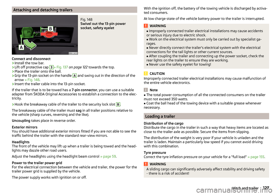
Attaching and detaching trailersFig. 148
Swivel out the 13-pin power
socket, safety eyelet
Connect and disconnect
›
Install the tow bar.
›
Lift off protective cap
3
» Fig. 137 on page 122 towards the top.
›
Place the trailer onto the ball.
›
Grip the 13-pin socket on the handle
A
and swing out in the direction of the
arrow » Fig. 148 .
›
Insert the trailer cable into the 13-pin socket.
If the trailer that is to be towed has a 7-pin connector, you can use a suitable
adapter from ŠKODA Original Accessories to establish a connection to the elec-
tricity.
›
Hook the breakaway cable of the trailer to the security lock slot
B
.
The breakaway cable of the trailer must sag in all trailer positions relative to
the vehicle (sharp curves, reversing and the like).
Uncoupling takes place in reverse order.
Exterior mirrors
You should have additional exterior mirrors fitted if you are not able to see the
traffic behind the trailer with the standard rear-view mirrors.
Headlights
The front of the vehicle may lift up when a trailer is being towed and the head-
lights may dazzle other road users.
Adjust the headlights using the headlight beam control » page 59.
Power to the trailer power grid
For the electrical connection between the vehicle and trailer, the power for the
trailer power grid is supplied by the vehicle.
The power supply works with ignition on or off.
With the ignition off, the battery of the towing vehicle is discharged by activa- ted consumers.
At low charge state of the vehicle battery power to the trailer is interrupted.WARNING■ Improperly connected trailer electrical installations may cause accidents
or serious injury due to electric shock.■
Work on the electrical system must only be carried out by specialist ga-
rages.
■
Never directly connect the trailer's electrical system with the electrical
connections for the tail lights or other current sources.
■
After coupling the trailer and connecting up the power socket, check the
rear lights on the trailer to ensure they are working.
■
Never use the safety eyelet for towing!
CAUTION
Improperly connected trailer electrical installations may cause malfunction of
the entire vehicle electronics.
Note
■ The total power consumption of all the connected consumers on the trailer
must not exceed 350 watts.■
Coat the ball head of the towing device with a suitable grease whenever
necessary.
Loading a trailer
Distribution of the cargo
Distribute the cargo in the trailer in such a way that heavy items are located as
close to the trailer axle as possible. Secure the items from slipping.
The distribution of the weight is very poor if your vehicle is unladen and the
trailer is laden. Maintain a particularly low speed if you cannot avoid driving
with this combination.
Tyre pressure
Correct the tyre inflation pressure on your vehicle for a “full load” » page 155.
WARNINGA sliding cargo can significantly adversely affect stability and driving safety
- there is a risk of accident!127Hitch and trailer
Page 130 of 208

Trailer loadThe permissible trailer load must not be exceeded under any circumstances.Permissible trailer loadEngineGearboxPermissible trailer load, braked (kg)Permissible trailer load, unbraked (kg)Gradients of up to 12 %Gradients of up to 8 %1.2 l/66 kW TSIMG9001000580DSG90010005901.2 l/81 kW TSIMG110012005901.4 l/92 kW TSIDSG12001200600DSG (Green tec)120012006101.6 l./81 kW MPIMG10001100580AG100011006001.4 l/66 kW TDI CRMG10001100610DSG100011006201.6 l/85 kW TDI CRMG12001200630WARNINGThe maximum permissible axle and draw-bar load and the permissible
weight of the trailer must not exceed - this could cause an accident!
Towing a trailer
Driving speed
For safety reasons, do not drive faster than 80 km/h when towing a trailer.
Immediately reduce your speed as soon as even the slightest swaying of the
trailer is detected. Never attempt to stop the trailer from “swaying” by acceler-
ating.
Brakes
Apply the brakes in good time! If the trailer is fitted with a trailer brake, apply
the brakes gently at first, then brake firmly. This will avoid brake jolts resulting
from the trailer wheels locking.
On downhill sections shift down a gear in good time to also use the engine as
a brake.
WARNINGAlways drive particularly carefully with the trailer.
CAUTION
If you tow a trailer frequently, you should also have your vehicle inspected be-
tween service intervals.
Anti-theft alarm system
When the vehicle is locked, the alarm is activated when the electrical connec-
tion to the trailer is interrupted.
Always switch off the anti-theft alarm system before a trailer is coupled or un-
coupled » page 54 .
Conditions for including a trailer in the anti-theft alarm system. The vehicle is factory-fitted with an anti-theft alarm system and towing
device.
The trailer is electrically connected to the towing vehicle by means of the
trailer socket.
128Driving
Page 135 of 208
WARNING■No modifications of any kind may be made to parts of the airbag system.■Any work on the airbag system including the installation and removal of
system components due to other repair work (e.g. removal of the steering
wheel) must only be carried out by a specialist garage.■
Never make any changes to the front bumper or the bodywork.
■
It is prohibited to manipulate individual parts of the airbag system, as this
might result in the airbag being deployed.
■
The protective function of the airbag system is sufficient for only one ac-
cident. The airbag system must then be replaced if the airbag has been de-
ployed.
Acceptance and recycling of used vehicles
Read and observe
on page 130 first.
ŠKODA meets the requirements of the brand and its products with regard to
protecting the environment and the preserving resources. All new ŠKODA ve-
hicles are 95% recyclable.
Note
You can find more detailed information about the trade-in and recycling of old
cars from a specialist garage.
Washing vehicle
Introduction
This chapter contains information on the following subjects:
Washing by hand
133
Automatic car wash systems
134
Washing with a high-pressure cleaner
134
The best way to protect your vehicle against harmful environmental influences
is frequent washing.
The longer insect residues, bird droppings, road salt and other aggressive de-
posits remain on the paintwork of your vehicle, the more detrimental their de-
structive effect can be. High temperatures, such as those caused by intensive
sun's rays, accentuate this caustic effect.
It is essential to also thoroughly clean the underside of the vehicle at the end
of the winter.WARNINGWhen washing your vehicle in the winter: Water and ice in the braking sys-
tem can affect the braking efficiency – risk of accident!
CAUTION
The temperature of the water used for cleaning must not exceed 60 °C – risk
of damaging the vehicle.
For the sake of the environment
Only wash the vehicle at washing bays intended for this purpose.
Washing by hand
Read and observe
and on page 133 first.
Soak the dirt with plenty of water and rinse as well as possible.
Clean the vehicle with a soft sponge, a washing glove or a washing brush.
Work from the top to the bottom – starting with the roof.
For stubborn dirt, agents specifically intended for this purpose are to be used. Wash out the sponge or washing glove thoroughly at short intervals.
Clean wheels, door sills and similar parts last. Use a second sponge for such areas.
Give the vehicle a good rinse after washing it and dry it off using a chamois
leather.
WARNINGProtect your hands and arms from sharp-edged metal parts when cleaning
the underfloor or the inside of the wheel housings or the wheel trims – risk
of cuts!
CAUTION
■ Only apply slight pressure when cleaning the vehicle's paintwork.■Do not wash your vehicle in bright sunlight – risk of paint damage.133Care and maintenance
Page 136 of 208
Automatic car wash systemsRead and observe
and on page 133 first.
The usual precautionary measures must be taken before washing the vehicle
in an automatic car wash system (e.g. closing the windows and the sliding/tilt-
ing roof etc.).
If your vehicle is fitted with any particular attached parts, such as a spoiler,
roof rack system etc., it is best to consult the operator of the car wash system
beforehand.
After an automatic wash with wax treatment, the lips of the wipers should be
cleaned with cleaning agents specially designed for the purpose, and then de-
greased.
CAUTION
■ Before driving through a car wash fold in the exterior mirrors - there is a risk
of damage.■
For vehicles with roof antenna the antenna rod should be unscrewed before
driving through a car wash - there is a risk of damage.
Washing with a high-pressure cleaner
Read and observe
and on page 133 first.
When washing the vehicle with a high-pressure cleaner, the instructions for
use of the equipment must be observed. This applies in particular to the pres-
sure used and to the spraying distance .
Maintain a sufficiently large distance to the parking aid sensors and soft mate-
rials such as rubber hoses or insulation material.
CAUTION
■ The films should not be washed with any high-pressure cleaners - risk of
damage » page 135 .■
Do not aim the water jet directly at the lock cylinders or the door or opening
joints when washing the vehicle in the winter – there is a risk of freezing.
■
The sensors of the parking aid can be sprayed only for a short time and there
must be a minimum distance of 10 cm - there is a risk of damage.
Cleaning vehicle exterior
Introduction
This chapter contains information on the following subjects:
Vehicle paint work
135
Films
135
Plastic parts
135
Rubber seals
136
Chrome and anodized parts
136
Windows and external mirrors
136
Headlight glasses
136
Door closing cylinder
137
Cavity protection
137
Jack
137
Wheels
137
Towing device and mounting recess
137
Under-body protection
138
Wiper blades
138
We recommend using vehicle care products from ŠKODA Original Accessories.
These are available from ŠKODA Partners. The usage instructions on the pack-
age must be observed.
WARNING■ Vehicle care products may be harmful to your health if not used according
to the instructions.■
Always keep the vehicle care products safe from people who are not com-
pletely independent, e.g. children - there is a danger of poisoning!
■
Protect your hands and arms from sharp-edged metal parts when clean-
ing the underfloor, the inside of the wheel housings or the wheel trims –
risk of cuts!
CAUTION
■ Do not use any insect sponges, rough kitchen sponges or similar cleaning
products – risk of damaging the paintwork surface.■
Cleaners that contain solvents can damage the material being cleaned.
134General Maintenance
Page 139 of 208

CAUTION■The headlights are never to be wiped dry - there is a risk of damaging the
protective lacquer and the headlight glass subsequently developing cracks.■
Do not use sharp objects to clean the glasses - there is a risk of damaging
the protective lacquer and the headlight glasses subsequently developing
cracks.
■
Do not use any aggressive cleaning or chemical solvent products to clean the
headlights – risk of damaging the headlight lenses.
Door closing cylinder
Read and observe
and on page 134 first.
Specific products must be used for de-icing door lock cylinders.
CAUTION
Make sure that as little water as possible gets into the locking cylinder when
washing the vehicle - there is a risk of freezing the lock cylinder!
Cavity protection
Read and observe
and on page 134 first.
All the cavities of your vehicle which are at risk from corrosion are protectedfor life by a layer of protective wax applied in the factory.
This wax protection does not need to be inspected or re-applied.
If any small amount of wax flow out of the cavities at high temperatures, these
must be removed with a plastic scraper and the stains cleaned using a petrole-
um cleaner.
WARNINGSafety regulations should be observed when using petroleum cleaner to re-
move wax – risk of fire!
Jack
Read and observe
and on page 134 first.
The jack is maintenance-free.
If necessary, the moving parts of the jack should be lubricated with a suitable lubricant.
Wheels
Read and observe
and on page 134 first.
Wheel rims
Also thoroughly wash the wheel rims when washing the vehicle on a regular basis.
Regularly remove salt and brake abrasion, otherwise the rim material will be
corroded.
Light alloy wheels
After washing thoroughly, treat the wheel rims with a protective product for
light alloy wheels.
For the treatment of wheel rims do not use products which may cause damage
to the paint on the rims.
CAUTION
■ Damage to the paint layer on the wheel rims must be touched up immediate-
ly.■
Severe layers of dirt on the wheels can also result in wheel imbalance. This
may show itself in the form of a wheel vibration which is transmitted to the
steering wheel which, in certain circumstances, can cause premature wear of
the steering. This means it is necessary to remove the dirt.
Towing device and mounting recess
Read and observe
and on page 134 first.
Close the mounting recess with the cover to prevent any dirt from getting in.
If dirt is present, clean the inner surfaces of the mounting recess and treat
with a suitable preservative.
Always check the ball head before hitching a trailer. Apply a suitable grease, if
necessary.
Use the protective cover when stowing away the tow bar, in order to stop the
boot from getting dirty.
CAUTION
Apply grease to the inner part of the mounting recess. Make sure you do not
remove any grease.137Care and maintenance
Page 143 of 208

Petrol and diesel refuellingFig. 150
Open fuel filler flap / unscrew tank cap / place the tank cap on
the fuel filler flap
Read and observe
and on page 140 first.
Refuelling can be done if the following conditions are met. The vehicle is unlocked.
The engine and the ignition are switched off.
›
Press on the fuel filler flap in the direction of the arrow
1
» Fig. 150 .
›
Open the flap in the direction of the arrow
2
.
›
Unscrew the tank cap in the direction of the arrow
3
.
›
Remove the tank cap and place on top of the fuel filler flap in direction of ar-
row
4
.
›
Insert the pump nozzle into the fuel filler tube as far as it will go.
The fuel tank is full just as soon as the pump nozzle switches off for the first
time »
.
›
Remove the pump nozzle from the fuel filler neck and put it back in the
pump.
›
Screw in the tank cap in the opposite direction of the arrow
3
until it audibly
clicks into place.
›
Close the fuel filler flap until it clicks into place.
Check that the fuel filler flap is closed properly.
WARNINGInstructions for filling the reserve canister■Never fill the reserve can inside the vehicle.■
Never place the reserve can on the vehicle.
■
Always place the reserve can on the floor.
■
We do not recommend carrying any fuel canisters in your vehicle for safe-
ty reasons. In the event of an accident, these canisters can become dam-
aged and fuel may escape – risk of fire!
CAUTION
■ The fuel tank is full as soon as the pump nozzle switches off for the first
time, provided the nozzle has been operated properly. Do not continue refuel-
ling.■
Be careful when filling diesel fuel from the spare canister and then do this
slowly and cautiously – danger of contaminating the body.
Note
The fuel tank has a capacity of about 55 litres, containing a reserve of approx.
7 litres .
Lead-free petrol
The correct fuel grades for your vehicle are specified on the inside of the fuel
filler flap.
Read and observe
and on page 140 first.
The vehicle can only be operated with unleaded petrol that meets the EN 2281)
standard.
All petrol engines can be operated using petrol that contains at most 10% bio-
ethanol (E10).
Unleaded petrol 95/min. 92 and 93 RON/ROZ
We recommend using unleaded fuel with an octane rating of 95 RON. Unlea-
ded petrol with the octane ratings 92 or 93 RON can also be used, but may re-
sult in a slight loss in performance and slightly increased fuel consumption.
Unleaded petrol min. 95 RON / ROZ
Use unleaded fuel with the octane rating 95 RON or higher.
1)
In Germany also DIN 51626-1 or E10 for unleaded petrol with octane number 91 or 95 or DIN 51626-2 or E5
for unleaded petrol with octane number 95 and 98.
141Inspecting and replenishing
Page 147 of 208
Close the flap›Lift the bonnet.›
Decouple the bonnet support and press into the holder designed to hold it.
›
Let the bonnet drop into the lock carrier lock from a height of around 20 cm –
do not push it in !
Check that the bonnet is closed properly.
WARNING■ If you notice that the lock is not properly engaged while driving, stop the
vehicle immediately and close the bonnet – risk of accident!■
Make sure that when closing the bonnet, no body parts are crushed -
there is danger of injury!
CAUTION
Never open the bonnet by the locking lever » Fig. 151.
Engine compartment overview
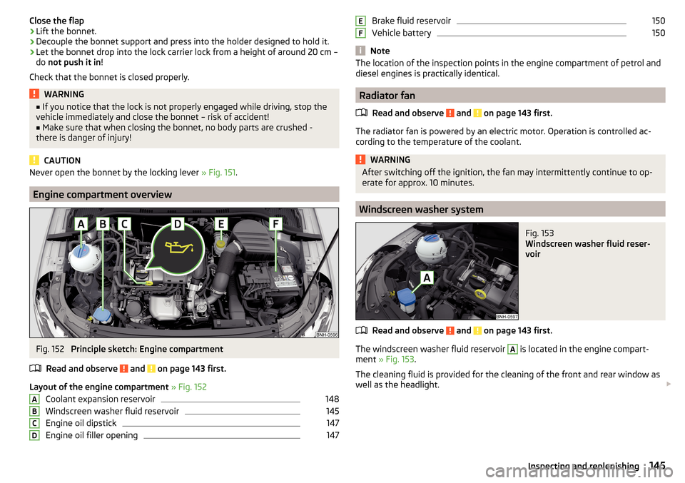
Fig. 152
Principle sketch: Engine compartment
Read and observe
and on page 143 first.
Layout of the engine compartment » Fig. 152
Coolant expansion reservoir
148
Windscreen washer fluid reservoir
145
Engine oil dipstick
147
Engine oil filler opening
147ABCDBrake fluid reservoir150
Vehicle battery
150
Note
The location of the inspection points in the engine compartment of petrol and
diesel engines is practically identical.
Radiator fan
Read and observe
and on page 143 first.
The radiator fan is powered by an electric motor. Operation is controlled ac-
cording to the temperature of the coolant.
WARNINGAfter switching off the ignition, the fan may intermittently continue to op-
erate for approx. 10 minutes.
Windscreen washer system
Fig. 153
Windscreen washer fluid reser-
voir
Read and observe and on page 143 first.
The windscreen washer fluid reservoir
A
is located in the engine compart-
ment » Fig. 153 .
The cleaning fluid is provided for the cleaning of the front and rear window as
well as the headlight.
EF145Inspecting and replenishing