warning light SKODA RAPID SPACEBACK 2015 1.G Repair Manual
[x] Cancel search | Manufacturer: SKODA, Model Year: 2015, Model line: RAPID SPACEBACK, Model: SKODA RAPID SPACEBACK 2015 1.GPages: 208, PDF Size: 29.2 MB
Page 148 of 208

The capacity of the reservoir is about 3.5 litres or about 5.4 litres on vehicles
that have a headlight cleaning system 1)
.
Clear water is not sufficient to intensively clean the windscreen and head-
lights. We recommend using clean water together with a screen cleaner from
the range of ŠKODA Original Accessories (with anti-freeze in winter), which
will remove any stubborn dirt.
In winter, the washing water should always be mixed with antifreeze even if
the vehicle has heated windscreen washer nozzles.
Under exceptional circumstances, methylated spirits can also be used if no
screen cleaner with anti-freeze is available. The concentration of methylated
spirits must not be more than 15 %. The anti-freeze protection at this concen-
tration is sufficient only to -5 °C.
CAUTION
■ Under no circumstances must radiator anti-freeze or other additives be add-
ed to the windscreen washer fluid.■
If the vehicle is fitted with a headlight cleaning system, only cleaning prod-
ucts which do not attack the polycarbonate coating of the headlights must be
added to the windscreen washer fluid.
■
Do not remove the filter from the windscreen washer fluid reservoir when re-
filling, as this may cause contamination of the liquid transportation system,
leading in turn to a windscreen washer system malfunction.
Engine oil
Introduction
This chapter contains information on the following subjects:
Specification
146
Checking the oil level
147
Replenishing
147
The engine has been factory-filled with a high-grade oil that can be use
throughout the year - except in extreme climate zones.
The engine oils are undergoing continuous further development. Thus the in- formation stated in this Owner's Manual is only correct at the time of publica-
tion.
ŠKODA Service Partners are informed about the latest changes by the manu-
facturer. We therefore recommend that the oil change be completed by a
ŠKODA Service Partner.
The specifications (VW standards) stated in the following can be indicated sep-
arately or together with other specifications on the bottle.
The engine oil should be changed after specified service intervals » page 46.WARNINGThe engine compartment of your car is a hazardous area. The following
warning instructions must be followed at all times when working in the en-
gine compartment » page 143.
CAUTION
Do not pour any additives into the engine oil – risk of serious damage to the
engine parts.
Note
■ Before a long drive we recommend that you purchase and carry with you en-
gine oil which complies with the specification for your vehicle.■
We recommend that you use oils from ŠKODA Original Accessories.
■
If your skin has come into contact with oil, it must be washed thoroughly.
Specification
Read and observe
and on page 146 first.
Vehicles with variable service intervals
Petrol enginesSpecification1.2 l/66, 81 kW TSIVW 504 001.4 l/92 kW TSIDiesel engines a)Specification1.4 l/66 kW TDI CRVW 507 001.6 l/85 kW TDI CRa)
Engine oil VW 505 01 can optionally be used in diesel engines
without a DPF.
1)
In some countries, 5.4 l. applies for both variants.
146General Maintenance
Page 149 of 208
Vehicles with fixed service intervalsPetrol enginesSpecification1.2 l/66, 81 kW TSI
VW 502 00
1.4 l/92 kW TSI1.6 l./81 kW MPIDiesel enginesa)Specification1.4 l/66 kW TDI CRVW 507 001.6 l/85 kW TDI CRa)
Engine oil VW 505 01 can optionally be used in diesel engines
without a DPF.
CAUTION
■
In an emergency, another engine oil to be refilled. To prevent damage to the
engine, a maximum of 0.5 litres only of the following engine oils may be used:
■ For petrol engine models: ACEA A3/ACEA B4 or API SN, (API SM);
■ For diesel engine models: ACEA C3 or API CJ-4.
Checking the oil level
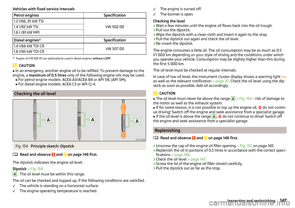
Fig. 154
Principle sketch: Dipstick
Read and observe
and on page 146 first.
The dipstick indicates the engine oil level .
Dipstick » Fig. 154
The oil level must be within this range.
The oil can be checked and topped up, if the following conditions are satisfied. The vehicle is standing on a horizontal surface.
The engine operating temperature is reached.
AThe engine is turned off.
The bonnet is open.
Checking the level›
Wait a few minutes until the engine oil flows back into the oil trough.
›
Pull out the dipstick.
›
Wipe the dipstick with a clean cloth and insert it again to the stop.
›
Pull the dipstick out again and check the oil level.
›
Re-insert the dipstick.
The engine consumes a little oil. The oil consumption may be as much as 0.5
l/1 000 km depending on your style of driving and the conditions under which
you operate your vehicle. Consumption may be slightly higher than this during
the first 5 000 km.
The oil level must be checked at regular intervals.
In case of low oil level, the instrument cluster display shows a warning light
as well as the relevant notification » page 37. Check the oil level using the dip-
stick as soon as possible. Add oil accordingly.
CAUTION
■ The oil level must never be above the range A » Fig. 154 - risk of damage to
the motor as well as the exhaust system.■
If for some reason, it is not possible to top up the engine oil,
do not contin-
ue driving! Switch off the engine and seek assistance from a specialist garage.
■
If the oil level is above the range
A
,
do not continue to drive! Switch off
the engine and seek assistance from a specialist garage.
Replenishing
Read and observe
and on page 146 first.
›
Unscrew the cap of the engine oil filler opening » Fig. 152 on page 145 .
›
Replenish the oil in portions of 0.5 litres in accordance with the correct speci-
fications » page 146 .
›
Check the oil level » page 147.
›
Screw the lid of the engine oil filler closed carefully.
›
Pull the dipstick out as far as the stop.
147Inspecting and replenishing
Page 150 of 208
Coolant
Introduction
This chapter contains information on the following subjects:
Checking the coolant level
148
Replenishing
149
The coolant provides cooling for the motor.
It consists of water and coolant additive with additives that protect the cooling
system against corrosion and prevents furring.
The coolant additive in the coolant must be at least 40%.
The coolant additive may be increased to a maximum of 60%.
The correct mixing ratio of water and coolant additive is to be checked if nec-
essary by a specialist garage or is to be restored if necessary.
The description of the coolant is shown in the coolant expansion reservoir
» Fig. 155 on page 148 .
WARNINGThe engine compartment of your car is a hazardous area. The following
warning instructions must be followed at all times when working in the en- gine compartment » page 143.■
The coolant is harmful to health.
■
Avoid contact with the coolant.
■
Coolant vapours are harmful to health.
■
Never open the end cover of the coolant expansion reservoir while the
engine is still warm. The cooling system is pressurised!
■
When opening the end cover of the coolant expansion reservoir, cover it
with a cloth to protect your face, hands and arms from hot steam or hot
coolant.
■
If any coolant splashes into your eyes, immediately rinse out your eyes
with clear water and contact a doctor as soon as possible.
■
Always keep the coolant in the original container, safe from people who
are not completely independent, especially children - there is a danger of
poisoning!
■
If coolant is swallowed, consult a doctor immediately.
■
Never spill operating fluids over the hot engine - risk of fire.
CAUTION■ Do not continue if for some reason it is not possible to fill with coolant un-
der the current circumstances! Switch off the engine and seek assistance from
a specialist garage.■
If the expansion tank is empty, do not top up with coolant. The system could
ventilate - there is a risk of engine damage,
do not continue driving! Switch
off the engine and seek assistance from a specialist garage.
■
The concentration of coolant additive in the coolant must never be under
40%.
■
Over 60% of coolant additive in the coolant reduces the antifreeze protec-
tion and cooling effect.
■
A coolant additive that does not comply with the correct specification can
significantly reduce the corrosion protection of the cooling system.
■
Any faults resulting from corrosion may cause a loss of coolant and can con-
sequently result in major engine damage.
■
Do not fill the coolant above the mark
A
. » Fig. 155 on page 148
■
If an error occurs, leading to the engine overheating, the help of a professio-
nal garage is to be sought - there is a risk of serious engine damage occurring.
■
Additional headlights and other attached components in front of the air inlet
impair the cooling efficiency of the coolant.
■
Never cover the radiator - there is a risk of the engine overheating.
Checking the coolant level
Fig. 155
Coolant expansion reservoir
Read and observe and on page 148 first.
The coolant expansion bottle is located in the engine compartment.
Coolant expansion reservoir » Fig. 155
Mark for the maximum permissible coolant level
Mark for the lowest permissible coolant level
AB148General Maintenance
Page 151 of 208
The coolant level should be kept between the marks A and B.
The coolant can be checked and topped up, if the following conditions are sat-
isfied.
The vehicle is standing on a horizontal surface.
The engine is turned off.
The engine is not heated.
The bonnet is open.
Checking the level›
Check the coolant level in the coolant expansion tank » Fig. 155.
If the engine is warm, the test result may be inaccurate. The level can also be
above the mark
A
» Fig. 155 .
In the event of an insufficient coolant level, a warning light is displayed in
the instrument cluster as well as the relevant notification » page 36. We still
recommend inspecting the coolant level directly at the reservoir from time to
time.
Loss of coolant
A loss of coolant is first and foremost an indication of a leak in the cooling sys-
tem. Do not merely top up the coolant. Have the cooling system checked by a
specialist garage.
Replenishing
Read and observe
and on page 148 first.
The coolant expansion tank must always contain a small amount of coolant
» page 148, in section Introduction .
›
Place a cloth over the cap of the coolant expansion tank and unscrew the
cap carefully .
›
Replenishing the coolant.
›
Turn the cap until it clicks into place.
Do not use an alternative additive if the specified coolant is not available. In
this case, use just water and have the correct mixing ratio of water and cool-
ant additive restored by a specialist garage as soon as possible.
Only top up with new coolant.
Brake fluid
Introduction
This chapter contains information on the following subjects:
Checking the brake fluid level
150
Specification
150
The brake fluid reservoir is located in the engine compartment » Fig. 156 on
page 150 .
WARNING■
The engine compartment of your car is a hazardous area. The following
warning instructions must be followed at all times when working in the en-
gine compartment » page 143.■
Do not use used brake fluid - the function of the brake system may be im-
paired – risk of accident!
CAUTION
■ Do not continue your journey if the fluid level has dropped below the “MIN”
marking » Fig. 156 on page 150 , do not continue to drive - risk of accidents!
Seek help from a specialist garage.■
Brake fluid damages the paintwork of the vehicle.
Note
■ The brake fluid is changed as part of a compulsory inspection service.■We recommend using brake fluids from the ŠKODA Original Accessories
range.149Inspecting and replenishing
Page 152 of 208
Checking the brake fluid levelFig. 156
Brake fluid reservoir
Read and observe and on page 149 first.
The fluid can be checked if the following conditions are met.The vehicle is standing on a horizontal surface.
The engine is turned off.
The bonnet is open.
Checking the level
›
Check the level of brake fluid in the reservoir » Fig. 156.
The level must be between the “MIN” and “MAX” markings.
A slight drop in the fluid level results when driving due to normal wear-and-
tear and automatic adjustment of the brake pads.
There may be an indication of a leak in the brake system, however, if the fluid
level drops significantly within a short time or if it drops below the “MIN” mark-
ing.
Too low brake fluid level is indicated by the warning light lighting up in the
instrument cluster as well as the relevant notification being displayed
» page 32 ,
Brake system
.
Specification
Read and observe
and on page 149 first.
To ensure the optimal functioning of the braking system, only use a brake fluid
meeting the standard VW 501 14 (this standard meets the requirements of
FMVSS 116 DOT4).
NoteWe recommend using brake fluids from the ŠKODA Genuine Accessories range.
Vehicle battery
Introduction
This chapter contains information on the following subjects:
Opening the cover
151
Checking the battery electrolyte level
152
Charging
152
Replacing
153
Disconnecting and reconnecting
153
Automatic load deactivation
153
The vehicle battery represents a power source for the motor to start and for
the supply of electrical consumers in the car.
Depending on the engine, the vehicle battery is either in the engine compart-
ment or the luggage compartment.
Warning symbols on the vehicle battery
SymbolMeaningAlways wear eye protection!Battery acid is severely caustic. Always wear gloves and eye pro-
tection!Keep fire, sparks, open flames and lit cigarettes well clear of the
vehicle battery!When charging the vehicle battery, a highly explosive gas mixture
is produced!Keep children away from the vehicle battery! 150General Maintenance
Page 153 of 208
WARNINGThere is risk of injuries, poisoning, chemical burns, explosions or fire when
working on the battery and on the electrical system. It is essential to com-
ply with the general applicable safety rules as well as the warning instruc-
tions outlined below.■
Keep the vehicle battery away from people who are not completely inde-
pendent, especially children.
■
Do not tilt the battery otherwise battery electrolyte may flow out of the
battery vent openings.
■
Protect your eyes by wearing safety goggles or a face shield – risk of
blindness!
■
Always wear protective gloves, eye and skin protection when handling
the vehicle battery.
■
The battery acid is strongly corrosive and must, therefore, be handled
with the greatest of care.
■
Corrosive fumes in the air irritate the air passages and lead to conjunctivi-
tis and inflammation of the air passages in the lungs.
■
Battery acid corrodes dental enamel and, if it comes into contact with the
skin, causes deep wounds that take a long time to heal.
■
If any battery acid comes into contact with your eyes, rinse the affected
eye immediately with clean water for several minutes and consult a doctor
immediately!
■
Splashes of acid on your skin or clothes should be neutralised as soon as
possible using soap suds and then rinsed with plenty of water.
■
If you swallow battery acid, consult a doctor immediately!
WARNING■ The use of open flames and light should be avoided.■Smoking and radio triggering activities should be avoided.■
Never use a damaged vehicle battery – risk of explosion!
■
Never charge a frozen or thawed vehicle battery – risk of explosion and
chemical burns!
■
Replace a frozen vehicle battery.
■
Never jump-start vehicle batteries with insufficient acid levels – risk of
explosion and chemical burns.
CAUTION
■ Improper handling of the vehicle battery may cause damage.■Ensure that battery acid does not come into contact with the bodywork – risk
of damage to the paintwork.■ If the vehicle has not been driven for more than 3-4 weeks, the battery will
discharge. Prevent the battery from discharging by disconnecting the battery's
negative terminal
or continuously charging the battery with a very low
charging current.■
Do not place the battery in direct daylight in order to protect the vehicle bat-
tery housing from the effects of ultra-violet light.
■
If the vehicle is frequently used for making short trips, the vehicle battery
will not have time to charge up sufficiently and may discharge.
Note
■ We recommend having all work on the vehicle battery carried out by a spe-
cialist garage.■
You should replace batteries older than 5 years.
Opening the cover
Fig. 157
Battery cover
Read and observe and on page 151 first.
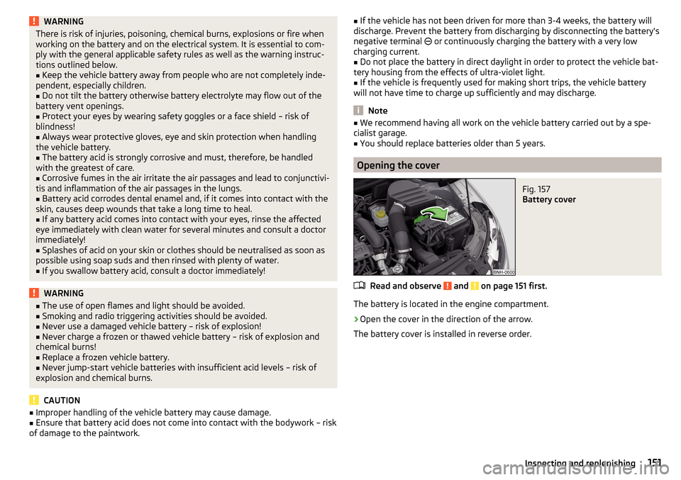
The battery is located in the engine compartment.
›
Open the cover in the direction of the arrow.
The battery cover is installed in reverse order.
151Inspecting and replenishing
Page 155 of 208
WARNING■When you charge a battery, hydrogen is released, and a highly explosive
gas mixture is also produced. An explosion can be caused through sparkling
over during unclamping or loosening of the cable plug while the ignition is
on.■
Creating a bridge between the poles on the battery (e.g. with metal ob-
jects - cables) creates a short circuit - risk of damage to the battery, explo-
sion and burning of the battery, jets of acid spurting out.
■
Avoid creating sparks when working with cables and electrical devices.
Strong sparking represents a risk of injury.
■
Before carrying out any work on the electrical system, switch off the en-
gine, the ignition and all electrical consumers and disconnect the negative
terminal
.
■
“Quick-charging” the vehicle battery is dangerous and requires a special
charger and specialist knowledge.
■
We therefore recommend that vehicle batteries be “rapidly charged” by a
specialist garage.
CAUTION
On vehicles with the START/STOP system, the pole terminal of the charger
must not be connected directly to the negative terminal of the vehicle battery,
but only to the engine earth » page 168, Jump-starting using the battery from
another vehicle .
Replacing
Read and observe
and on page 151 first.
The new vehicle battery must have the same capacity, voltage, current and
size as the original battery. Suitable vehicle battery types can be purchased
from a specialist garage.
We recommend you have the battery replaced by a specialist garage.
Disconnecting and reconnecting
Read and observe
and on page 151 first.
Disconnecting
›
Switch off the ignition.
›
First, disconnect the negative terminal
first, then the positive
terminal
of the battery.
Connecting›First, connect the positive first, then the negative battery terminal.
After disconnecting and re-connecting the vehicle battery, the following func-
tions or devices are partially or completely inoperative.Function / deviceCommissioningTime settings» page 31
CAUTION
■ Disconnect the vehicle battery only with the ignition turned off - there is a
risk of damaging the electrical system of the vehicle.■
Under no circumstances must the battery cables be connected incorrectly –
risk of a cable fire.
Note
■ After disconnecting and re-connecting the vehicle battery, we recommend
having the vehicle checked by a specialist to ensure that the full functionality
of all electrical systems is guaranteed.■
The data of the multi-function display will be reset.
Automatic load deactivation
Read and observe
and on page 151 first.
The vehicle's electrical system automatically prevents the battery from dis-
charging when the battery is being heavily used. This manifests itself by the
following. ▶ The idling speed is raised to allow the generator to deliver more electricity to
the electrical system.
▶ Where necessary, large convenience consumers such as seat heaters and
rear window heaters have their power limited or are shut off completely in
the event of an emergency.
CAUTION
■ Despite such intervention by the vehicle electric system management, the
vehicle battery may be drained. For example, when the ignition is switched on
a long time with the engine turned off or the side or parking lights are turned
on during longer parking.■
Consumers that are supplied via a 12-V power socket can cause the vehicle
battery to discharge when the ignition is switched off.
153Inspecting and replenishing
Page 157 of 208
Always store wheels or tyres in a cool, dry place that is as dark as possible.
Tyres which are not fixed to a wheel trim should be stored upright.
Tyre age
Tyres age and lose their original characteristics, even if they are not being
used. The service life of the tyres is 6 years. Therefore, we recommend not us-
ing tyres that are older than 6 years.
Wheel bolts
Wheels and wheel bolts are matched to each other in terms of design. We rec-
ommend that you use wheel rims and wheel bolts from ŠKODA Original Acces-
sories.WARNINGNever use tyres if you do not know anything about the condition and age.
Tyre pressure
Fig. 159
Label with a table of tyre sizes and tyre pressure value / inflate
tyres
Read and observe
on page 154 first.
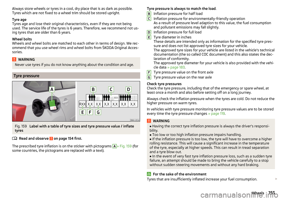
The prescribed tyre inflation is on the sticker with pictograms
A
» Fig. 159 (for
some countries, the pictograms are replaced with a text).
Tyre pressure is always to match the load .
Inflation pressure for half load
Inflation pressure for environmentally-friendly operation
As a result of pressure level adaption to this value, the fuel consumption
and pollutant emissions may fall slightly.
Inflation pressure for full load
Tyre diameter in inches
These details are intended only as information for the specified tyre pres-
sure and does not list approved tyre sizes for your vehicle.
The approved tyre sizes for your vehicle are listed in the vehicle's technical
documentation (the so called COC document) and this also states the dec-
laration of conformity.
The approved tyre diameter for your vehicle is also provided with the vehi-
cle data » page 183 .
Tyre pressure value on the front axle
Tyre pressure value on the rear axle
Check tyre pressures
Check the tyre pressure, including that of the emergency or spare wheel, at
least once a month and also before setting off on a long journey.
Always check the inflation pressure when the tyres are cold. Do not reduce the
higher pressure on warm tyres.
In vehicles with tyre pressure monitoring tyre pressure values are to be stored
every time the tyre pressure changes » page 119.WARNING■
Having the correct tyre inflation pressure is always the driver's responsi-
bility.■
Too low or too high inflation pressure impairs handling.
■
If the inflation pressure is too low, the tyre will have to overcome a higher
rolling resistance. This will cause a significant increase in the temperature
of the tyre, especially at higher speeds. This can result in tread separation
and a tyre blow out.
■
In the event of very fast tyre inflation pressure loss, such as a sudden tyre
failure, an attempt should be made to bring the vehicle carefully to a stop
without sudden steering movements and without any hard braking.
For the sake of the environment
Tyres that are insufficiently inflated increase your fuel consumption. BCDEFG155Wheels
Page 163 of 208
The fire extinguisher is attached by two straps in a holder underneath the driv-
er's seat.
Removing/attaching›
Loosen the two straps by pulling the buckles in the direction of the arrow
» Fig. 163 .
›
Remove the fire extinguisher.
›
For mounting, fit the fire extinguisher back into the holder and secure it with
straps.
Please read the instructions which are attached to the fire extinguisher.
Pay attention to the expiration date of the fire extinguisher. Proper function-
ing of the fire extinguisher is not assured once it has passed its expiry date.
WARNINGThe fire extinguisher must always be secured safely so that they do not
come loose when making an emergency braking or in a vehicle collision
which could cause injuries to occupants.
Note
The fire extinguisher is part of the scope of delivery in certain countries only.
Vehicle tool kit
Fig. 164
Vehicle tool kit
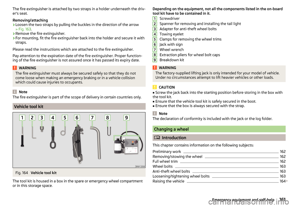
The tool kit is housed in a box in the spare or emergency wheel compartment
or in this storage space.
Depending on the equipment, not all the components listed in the on-board
tool kit have to be contained in it.
Screwdriver
Spanner for removing and installing the tail light
Adapter for anti-theft wheel bolts
Towing eyelet
Clamps for removing the wheel trims
Jack with sign
Wheel wrench
Extraction pliers for wheel bolt caps
Breakdown kitWARNINGThe factory-supplied lifting jack is only intended for your model of vehicle.
Under no circumstances attempt to lift heavier vehicles or other loads.
CAUTION
■ Screw the jack back into the starting position before storing in the box with
the tool kit.■
Ensure that the vehicle tool kit is safely secured in the boot.
■
Ensure that the box is always secured with the strap.
Note
The declaration of conformity is included with the jack or the log folder.
Changing a wheel
Introduction
This chapter contains information on the following subjects:
Preliminary work
162
Removing/stowing the wheel
162
Full wheel trim
162
Wheel bolts
163
Anti-theft wheel bolts
163
Loosening/tightening wheel bolts
163
Raising the vehicle
164
123456789161Emergency equipment and self-help
Page 164 of 208
Remove the wheel / fix165Follow-up work165
For your own safety and the safety of the passengers, the following instruc-
tions must be observed before changing a wheel on the road.
Switch on the hazard warning lights system.
Place the warning triangle at the prescribed distance.
Park the vehicle as far away as possible from the flowing traffic.
Choose a location with a flat, solid surface.
Have all the occupants get out. The passengers should not stand on the
road (instead they should remain behind a crash barrier, for instance) while
the wheel is being changed.
Preliminary work
Before changing the wheel, the following work must be carried out.
›
Switch off the engine.
›
For vehicles with manual transmission select gear 1.
›
On vehicles with automatic transmission , place the selector lever in the P
position.
›
Firmly apply the handbrake.
›
Uncouple trailer, if attached.
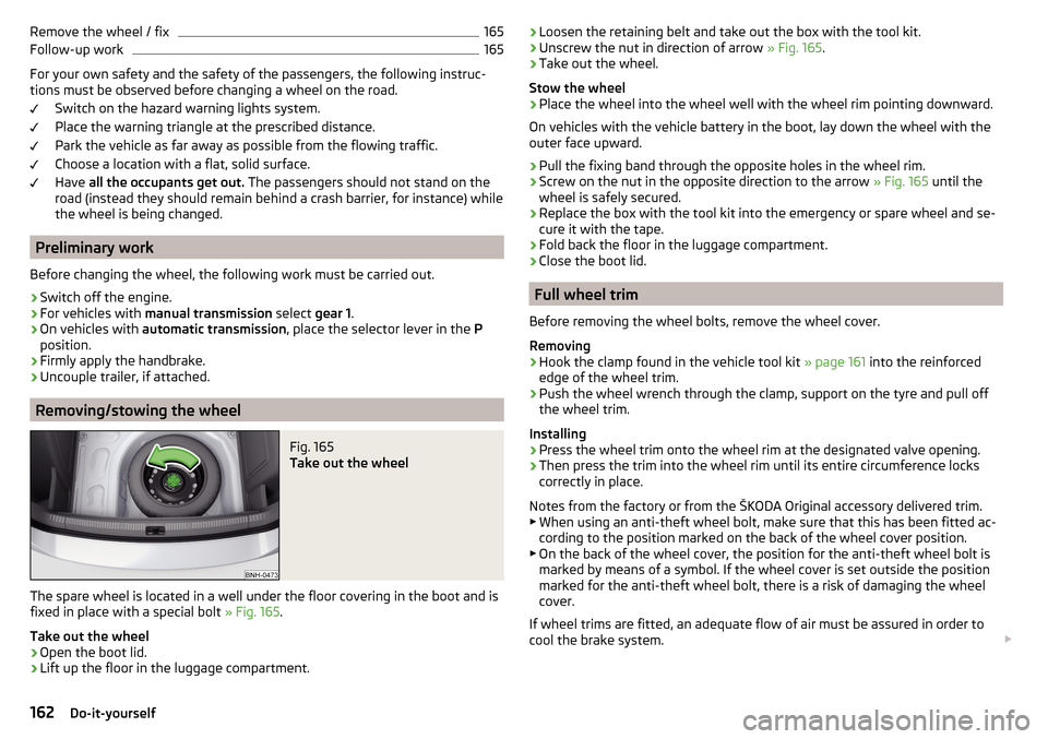
Removing/stowing the wheel
Fig. 165
Take out the wheel
The spare wheel is located in a well under the floor covering in the boot and is
fixed in place with a special bolt » Fig. 165.
Take out the wheel
›
Open the boot lid.
›
Lift up the floor in the luggage compartment.
› Loosen the retaining belt and take out the box with the tool kit.›Unscrew the nut in direction of arrow
» Fig. 165.›
Take out the wheel.
Stow the wheel
›
Place the wheel into the wheel well with the wheel rim pointing downward.
On vehicles with the vehicle battery in the boot, lay down the wheel with the
outer face upward.
›
Pull the fixing band through the opposite holes in the wheel rim.
›
Screw on the nut in the opposite direction to the arrow » Fig. 165 until the
wheel is safely secured.
›
Replace the box with the tool kit into the emergency or spare wheel and se-
cure it with the tape.
›
Fold back the floor in the luggage compartment.
›
Close the boot lid.
Full wheel trim
Before removing the wheel bolts, remove the wheel cover.
Removing
›
Hook the clamp found in the vehicle tool kit » page 161 into the reinforced
edge of the wheel trim.
›
Push the wheel wrench through the clamp, support on the tyre and pull off
the wheel trim.
Installing
›
Press the wheel trim onto the wheel rim at the designated valve opening.
›
Then press the trim into the wheel rim until its entire circumference locks
correctly in place.
Notes from the factory or from the ŠKODA Original accessory delivered trim.
▶ When using an anti-theft wheel bolt, make sure that this has been fitted ac-
cording to the position marked on the back of the wheel cover position.
▶ On the back of the wheel cover, the position for the anti-theft wheel bolt is
marked by means of a symbol. If the wheel cover is set outside the position
marked for the anti-theft wheel bolt, there is a risk of damaging the wheel
cover.
If wheel trims are fitted, an adequate flow of air must be assured in order to
cool the brake system.
162Do-it-yourself