Direction lights SKODA RAPID SPACEBACK 2015 1.G Owner's Manual
[x] Cancel search | Manufacturer: SKODA, Model Year: 2015, Model line: RAPID SPACEBACK, Model: SKODA RAPID SPACEBACK 2015 1.GPages: 208, PDF Size: 29.2 MB
Page 55 of 208

Acoustic signals when locking / unlocking
For vehicles with an anti-theft alarm system, the acoustic signals can be ena- bled / disabled in the Infotainment » Owner´s Manual Infotainment , chap-
ter CAR - Vehicle Settings or be set by a specialist garage.
Opening/closing a door
Fig. 39
Door handle/door opening lever
Read and observe
and on page 50 first.
Opening from the outside
›
Unlock the vehicle.
›
Pull on the door handle
A
in the direction of the arrow » Fig. 39.
Opening from the inside
›
Pull on door opening lever
B
of the door and push the door away from you.
Closing from the inside
›
Grasp pull handle
C
and close the door.
WARNING■ Make sure that the door has closed correctly as it can open suddenly
while driving – risk of death!■
Only open and close the door when there is no one in the opening/closing
range – risk of injury!
■
An opened door can close automatically if there is a strong wind or the
vehicle is on an incline – risk of injury!
■
Never drive with the doors open - there is a risk of death!
Child safety lockFig. 40
Rear door: Child safety system switch on / off
Read and observe
and on page 50 first.
The child safety lock prevents the rear door from being opened from the in- side. The door can only be opened from the outside.
Switching the child safety system on/off » Fig. 40
Switching on
Switching off
You can switch the child safety lock on and off using the vehicle key.
Malfunctions
Read and observe
and on page 50 first.
Fault with the central locking
If the indicator light in the driver's door initially flashes quickly for around 2
seconds, and then lights up for 30 seconds without interruption before flash-
ing again slowly, you will need to seek the assistance of a specialist garage.
In the event of a fault in the central locking system, only the driver's door can
be locked or unlocked with the key. The other doors and the boot lid can be
locked or unlocked manually.
▶ Locking door » page 172.
▶ Unlocking the boot lid » page 172.
53Unlocking and opening
Page 67 of 208
If the engine is switched off when the heating is on and turned back on again
within 10 minutes, the heating is continued.
Note
■ If the on-board voltage decreases, the heating switches off automatically
» page 153 , Automatic load deactivation .■
If the light is flashing inside the button the heater is off due to low battery.
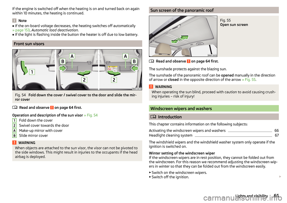
Front sun visors
Fig. 54
Fold down the cover / swivel cover to the door and slide the mir-
ror cover
Read and observe
on page 64 first.
Operation and description of the sun visor » Fig. 54
Fold down the cover
Swivel cover towards the door
Make-up mirror with cover
Slide mirror cover
WARNINGWhen objects are attached to the sun visor, the visor can not be pivoted to
the side windows. This might result in injuries to the occupants if the head
airbag is deployed.12ABSun screen of the panoramic roofFig. 55
Open sun screen
Read and observe on page 64 first.
The sunshade protects against the blazing sun.
The sunshade of the panoramic roof can be opened manually in the direction
of arrow or closed in the opposite direction of the arrow » Fig. 55.
WARNINGWhen operating the sun blind, proceed with caution to avoid causing crush-
ing injuries – risk of injury!
Windscreen wipers and washers
Introduction
This chapter contains information on the following subjects:
Activating the windscreen wipers and washers
66
Headlight cleaning system
67
The windshield wipers and the windshield washer system only operate if the
ignition is switched on.
Winter setting of the windscreen wiper
If the windscreen wipers are in rest position, they cannot be folded out from
the windscreen. For this reason we recommend adjusting the windscreen wip-
ers in winter so that they can be folded out from the windscreen easily.
▶ Switch on the windscreen wipers.
▶ Switch off the ignition.
65Lights and visibility
Page 73 of 208

Buttons for the seat heating » Fig. 63
Left seat heating
Right seat heating
Switching on›
Press button
or
» Fig. 63 .
Pressing once switches the seat heating on at its maximum level - Level 2.
With repeated pressing of the switch, the intensity of the heating is reduced
until it is switched off.
The level of the seat heating is indicated by the number of illuminated warning
lights in the switch.
WARNINGIf you have a subdued pain and/or temperature sensitivity, e.g. through
medication, paralysis or because of chronic illness (e.g. diabetes), we rec-
ommend not to use the seat heating. There may be difficult to heal burns. If
the seat heating is used, we recommend to make regular breaks in your
journey when driving long distances, so that the body can recuperate from
the stress of the journey. Please consult your doctor, who can evaluate
your specific condition.
CAUTION
The following instructions must be observed to avoid damage to the seats.■Do not kneel on the seats or otherwise apply concentrated pressure to them.■
Do not turn on any of the seat heaters if seats are not occupied.
■
Do not switch on the relevant seat heating if the seats have objects attached
to or placed on them, for example a child seat, a bag, etc.
■
When there are additional protective covers or protective covers mounted on
each of the seats, do not turn the seat heating on.
Note
■ If the heaters for the rear seats are set to their highest intensity - level 2,
they are automatically switched down to level 1 after 10 minutes.■
If the on-board voltage decreases, the seat heating switches off automati-
cally » page 153 , Automatic load deactivation .
Front armrest settingFig. 64
Raise armrest
The armrest is adjustable in height.
Raise
›
Lift the armrest in the direction of arrow into one of the five locking positions
» Fig. 64 .
Folding down
›
Raise the armrest in the direction of the arrow until it stops » Fig. 64.
›
Fold down the rear armrest.
Rear armrest setting
Fig. 65
Fold down armrest
The armrest can be folded down to increase comfort.
Lowering / raising
›
Pull on the loop
A
and fold down the armrest forward in the direction of the
arrow » Fig. 65 .
Raising takes place in reverse order.
71Seats and head restraints
Page 93 of 208
WARNING■For your own safety and that of other road users, ensure that all the win-
dows are free of ice, snow and misting. The blower should always be on to
prevent the windows from misting up.■
Under certain circumstances, air at a temperature of about 5 °C can flow
out of the vents when the cooling system is switched on.
CAUTION
■ The air inlet in front of the windscreen must be free from ice, snow or leaves,
for example, to ensure that the heating and cooling system works properly.■
After switching on the cooling Condensation from the evaporator of the air
conditioning may drip down and form a puddle below the vehicle. This is not a
leak!
■
If the coolant temperature is too high, the cooling system is switched off to
ensure that the engine cools down.
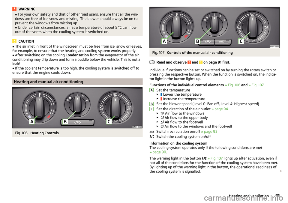
Heating and manual air conditioning
Fig. 106
Heating Controls
Fig. 107
Controls of the manual air conditioning
Read and observe
and on page 91 first.
Individual functions can be set or switched on by turning the rotary switch or
pressing the respective button. When the function is switched on, the indica-
tor light in the button lights up.
Functions of the individual control elements » Fig. 106 and » Fig. 107
Set the temperature
▶ Lower the temperature
▶ Increase the temperature
Set the blower speed (Level 0: Fan off, Level 4: Highest speed)
Set the direction of the air outlet » page 94
▶ Air flow to the windows
▶ Air flow to the upper body
▶ Air flow to the footwell
▶ Air flow to the windows and the footwell
Switch recirculation on/off » page 93
Switch the cooling system on/off
Information on the cooling system
The cooling system operates only if the following conditions are met
» page 90 .
The warning light in the button
» Fig. 107 lights up after activation, even if
not all of the conditions for the function of the cooling system have been met.
By lighting up of the warning light in the button, the operational readiness of
the cooling system is signalled.
ABC91Heating and ventilation
Page 115 of 208

Approximate range of sensors (in cm)Area » Fig. 124Version 1
(3 sensors)Version 2
(7 sensors)A-120B-60C160160D6060
Audible signals
The interval between the acoustic signals becomes shorter as the clearance is
reduced. A continuous tone sounds from a distance of approx. 30 cm - danger
area. From this moment on do not continue driving!
The acoustic signals can be set in the Infotainment » Owner´s Manual Infotain-
ment , chapter CAR - Vehicle Settings .
Towing a trailer
When towing, or when another accessory is connected to the trailer socket on-
ly the areas
A
and
B
» Fig. 124 are active in the system.
Note
The signal tones for front obstacle recognition are factory-set to be higher
than for rear obstacle recognition.
Display in the Infotainment display
Fig. 125
Display
Read and observe and on page 112 first.
Function keys and obstacle warning » Fig. 125 Depending on the Infotainment type: Switching off park assistant dis-
play. Switching audible parking signals on/off.Message: Look! Safe to move?Colour of an object detected in the collision area (the distance to the
obstacle is less than 30 cm).
Stop driving in the direction of the ob-
stacle!Colour of an object detected in the manoeuvring area (the distance to
the obstacle is more than 30 cm).Colour of an object detected in the outside the manoeuvring area (the
distance to the obstacle is more than 30 cm).System failure (there is no indication of obstacles).
Activation / deactivation
Fig. 126
System key (option 2)
Read and observe and on page 112 first.
Activation
The activation of the system is initiated when the reverse gear is engaged, or
vehicles with the Variant 2, also by pressing the symbol key
» Fig. 126
.
This is confirmed by a short acoustic signal (the symbol in the button lights
up).
Deactivation
On vehicles with Version 1, the system can be deactivated by moving out of re-
verse gear.
For vehicles with Version 2, the system is deactivated by pressing the symbol
button or automatically at a speed over 10 km/h (the symbol
in the but-
ton goes out).
113Assist systems
Page 129 of 208
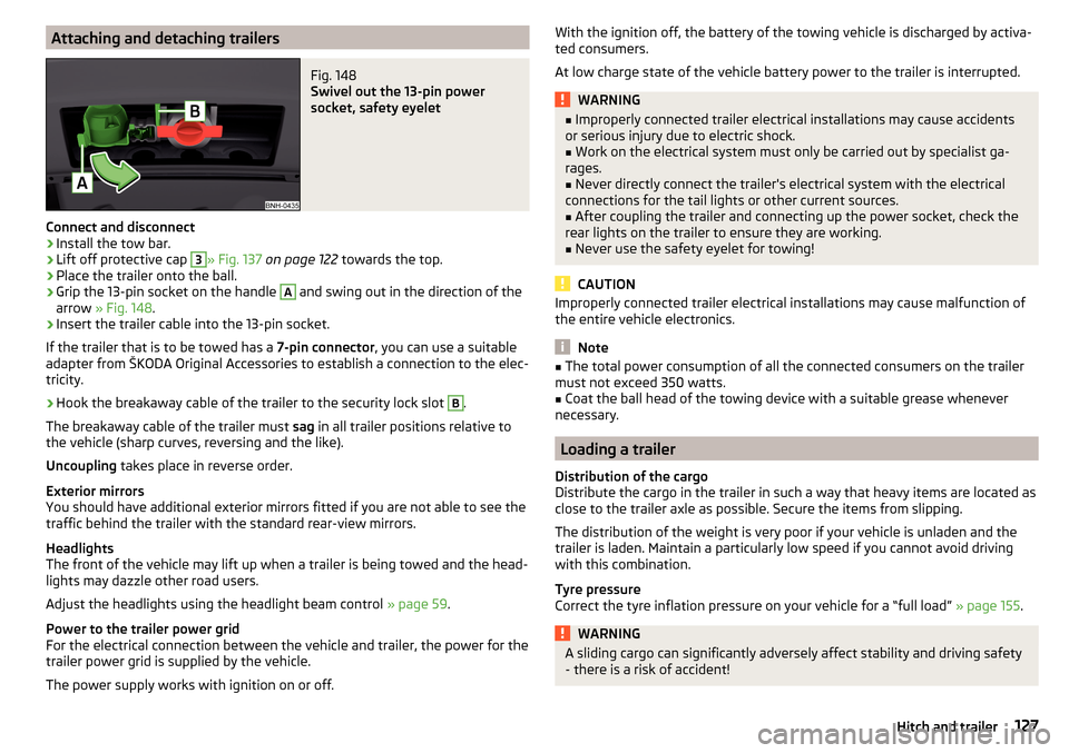
Attaching and detaching trailersFig. 148
Swivel out the 13-pin power
socket, safety eyelet
Connect and disconnect
›
Install the tow bar.
›
Lift off protective cap
3
» Fig. 137 on page 122 towards the top.
›
Place the trailer onto the ball.
›
Grip the 13-pin socket on the handle
A
and swing out in the direction of the
arrow » Fig. 148 .
›
Insert the trailer cable into the 13-pin socket.
If the trailer that is to be towed has a 7-pin connector, you can use a suitable
adapter from ŠKODA Original Accessories to establish a connection to the elec-
tricity.
›
Hook the breakaway cable of the trailer to the security lock slot
B
.
The breakaway cable of the trailer must sag in all trailer positions relative to
the vehicle (sharp curves, reversing and the like).
Uncoupling takes place in reverse order.
Exterior mirrors
You should have additional exterior mirrors fitted if you are not able to see the
traffic behind the trailer with the standard rear-view mirrors.
Headlights
The front of the vehicle may lift up when a trailer is being towed and the head-
lights may dazzle other road users.
Adjust the headlights using the headlight beam control » page 59.
Power to the trailer power grid
For the electrical connection between the vehicle and trailer, the power for the
trailer power grid is supplied by the vehicle.
The power supply works with ignition on or off.
With the ignition off, the battery of the towing vehicle is discharged by activa- ted consumers.
At low charge state of the vehicle battery power to the trailer is interrupted.WARNING■ Improperly connected trailer electrical installations may cause accidents
or serious injury due to electric shock.■
Work on the electrical system must only be carried out by specialist ga-
rages.
■
Never directly connect the trailer's electrical system with the electrical
connections for the tail lights or other current sources.
■
After coupling the trailer and connecting up the power socket, check the
rear lights on the trailer to ensure they are working.
■
Never use the safety eyelet for towing!
CAUTION
Improperly connected trailer electrical installations may cause malfunction of
the entire vehicle electronics.
Note
■ The total power consumption of all the connected consumers on the trailer
must not exceed 350 watts.■
Coat the ball head of the towing device with a suitable grease whenever
necessary.
Loading a trailer
Distribution of the cargo
Distribute the cargo in the trailer in such a way that heavy items are located as
close to the trailer axle as possible. Secure the items from slipping.
The distribution of the weight is very poor if your vehicle is unladen and the
trailer is laden. Maintain a particularly low speed if you cannot avoid driving
with this combination.
Tyre pressure
Correct the tyre inflation pressure on your vehicle for a “full load” » page 155.
WARNINGA sliding cargo can significantly adversely affect stability and driving safety
- there is a risk of accident!127Hitch and trailer
Page 164 of 208
Remove the wheel / fix165Follow-up work165
For your own safety and the safety of the passengers, the following instruc-
tions must be observed before changing a wheel on the road.
Switch on the hazard warning lights system.
Place the warning triangle at the prescribed distance.
Park the vehicle as far away as possible from the flowing traffic.
Choose a location with a flat, solid surface.
Have all the occupants get out. The passengers should not stand on the
road (instead they should remain behind a crash barrier, for instance) while
the wheel is being changed.
Preliminary work
Before changing the wheel, the following work must be carried out.
›
Switch off the engine.
›
For vehicles with manual transmission select gear 1.
›
On vehicles with automatic transmission , place the selector lever in the P
position.
›
Firmly apply the handbrake.
›
Uncouple trailer, if attached.
Removing/stowing the wheel
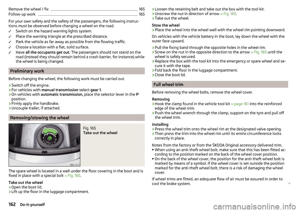
Fig. 165
Take out the wheel
The spare wheel is located in a well under the floor covering in the boot and is
fixed in place with a special bolt » Fig. 165.
Take out the wheel
›
Open the boot lid.
›
Lift up the floor in the luggage compartment.
› Loosen the retaining belt and take out the box with the tool kit.›Unscrew the nut in direction of arrow
» Fig. 165.›
Take out the wheel.
Stow the wheel
›
Place the wheel into the wheel well with the wheel rim pointing downward.
On vehicles with the vehicle battery in the boot, lay down the wheel with the
outer face upward.
›
Pull the fixing band through the opposite holes in the wheel rim.
›
Screw on the nut in the opposite direction to the arrow » Fig. 165 until the
wheel is safely secured.
›
Replace the box with the tool kit into the emergency or spare wheel and se-
cure it with the tape.
›
Fold back the floor in the luggage compartment.
›
Close the boot lid.
Full wheel trim
Before removing the wheel bolts, remove the wheel cover.
Removing
›
Hook the clamp found in the vehicle tool kit » page 161 into the reinforced
edge of the wheel trim.
›
Push the wheel wrench through the clamp, support on the tyre and pull off
the wheel trim.
Installing
›
Press the wheel trim onto the wheel rim at the designated valve opening.
›
Then press the trim into the wheel rim until its entire circumference locks
correctly in place.
Notes from the factory or from the ŠKODA Original accessory delivered trim.
▶ When using an anti-theft wheel bolt, make sure that this has been fitted ac-
cording to the position marked on the back of the wheel cover position.
▶ On the back of the wheel cover, the position for the anti-theft wheel bolt is
marked by means of a symbol. If the wheel cover is set outside the position
marked for the anti-theft wheel bolt, there is a risk of damaging the wheel
cover.
If wheel trims are fitted, an adequate flow of air must be assured in order to
cool the brake system.
162Do-it-yourself
Page 172 of 208

›Only then approach correctly when the rope is taut.
The maximum towing speed is 50 km/h.
Driver of the towed vehicle›
Switch on the ignition so that the steering wheel is not locked and so that
the turn signal lights, windscreen wipers and windscreen washer system can
be used.
›
Take the vehicle out of gear or move the selector lever into position N if the
vehicle is fitted with an automatic gearbox.
Please note that the brake servo unit and power steering only operate if the
engine is running. If the engine is not running, significantly more physical force
is required to depress the brake pedal and steer the vehicle.
If using a tow rope, ensure that it is always kept taught.
General information for the towing process
Both drivers should be familiar with the problems which might possibly occur while a vehicle is being towed. Unskilled drivers should not attempt to tow an-
other vehicle or to be towed in one.
The vehicle must be transported on a special breakdown vehicle or trailer if it
is not possible to tow the vehicle in the way described or if the towing dis-
tance is greater than 50 km.
If the gearbox no longer contains any oil, your vehicle must only be towed with
the front axle raised clear of the ground or on a breakdown vehicle or trailer.
To protect both vehicles when tow-starting or towing, the tow rope should be
elastic. Thus only plastic fibre rope or a rope made out of a similarly elastic ma-
terial should be used.
Attach the tow rope or the tow bar to the towing eyes » page 170 or
» page 171 to the detachable ball head of the towing equipment » page 121 .
WARNING■
When towing, exercise increased caution.■For towing no spiral tow rope is to be used » Fig. 174- , the towing eye
may unscrew out of the vehicle - there is a risk of accidents.■
The tow rope should not be twisted - there is a risk of accidents.
CAUTION■ Do not start engine by towing - there is a risk of damaging the engine parts.
The battery from another vehicle can be used as a jump-start aid » page 168,
Jump-starting .■
There is always a risk of excessive stresses and damage resulting at the
points to which you attach the tow rope or tow bar when you attempt to tow a
vehicle which is not standing on a paved road.
Note
We recommend using a tow rope from ŠKODA Original Accessories, which is
available from a ŠKODA Partner.
Front towing eye
Fig. 175
Removing the cap/installing the towing eye
Read and observe
and on page 170 first.
Removing/installing the cap
›
Press on the cap in the direction of the arrow
1
» Fig. 175 .
›
Remove the cap in the direction of the arrow
2
.
›
After unscrewing the cap of the towing eye, insert the cap in the region of
the arrow
1
and then press the opposite side of the cap.
The cap must engage firmly.
Removing/installing the towing eye
›
Manually screw the towing eye as far as it will go in the direction of the ar-
row
3
» Fig. 175 » .
For tightening purposes, we recommend, for example, using the wheel
wrench, towing eye from another vehicle or a similar object that can be pushed through the eye.
170Do-it-yourself
Page 177 of 208
CAUTION■“Never repair” fuses, and do not replace them with fuses of a higher amper-
age – risk of fire! This may also cause damage at other points in the electrical
system.■
If a newly inserted fuse blows again after a short time, have the electrical
system checked as quickly as possible by a specialist garage.
■
A blown fuse is recognisable by the molten metal strip. Replace the faulty
fuse with a new one of the same amperage.
Note
■
We recommend always carrying replacement fuses in the vehicle. A box of
replacement fuses and bulbs can be purchased from ŠKODA Genuine Accesso-
ries.■
There can be several power-consuming devices for one fuse.
■
Multiple fuses may exist for a single power-consuming device.
Fuses in the dash panel
Fig. 183
Remove the fuse box cover.
Read and observe and on page 174 first.
The fuses are located on the bottom of the dash panel behind a cover.
Replacing fuses
›
Grip the fuse box cover at point
A
and take-out in the direction of arrow
» Fig. 183 .
›
Remove the plastic clip from the holder in the fuse box cover.
›
Place the clip on the respective fuse and pull this fuse out.
›
Insert a new fuse.
›
Replace the bracket at the original position.
›
Insert the top edge of the cover into the dash panel first.
Carefully push the cover in.
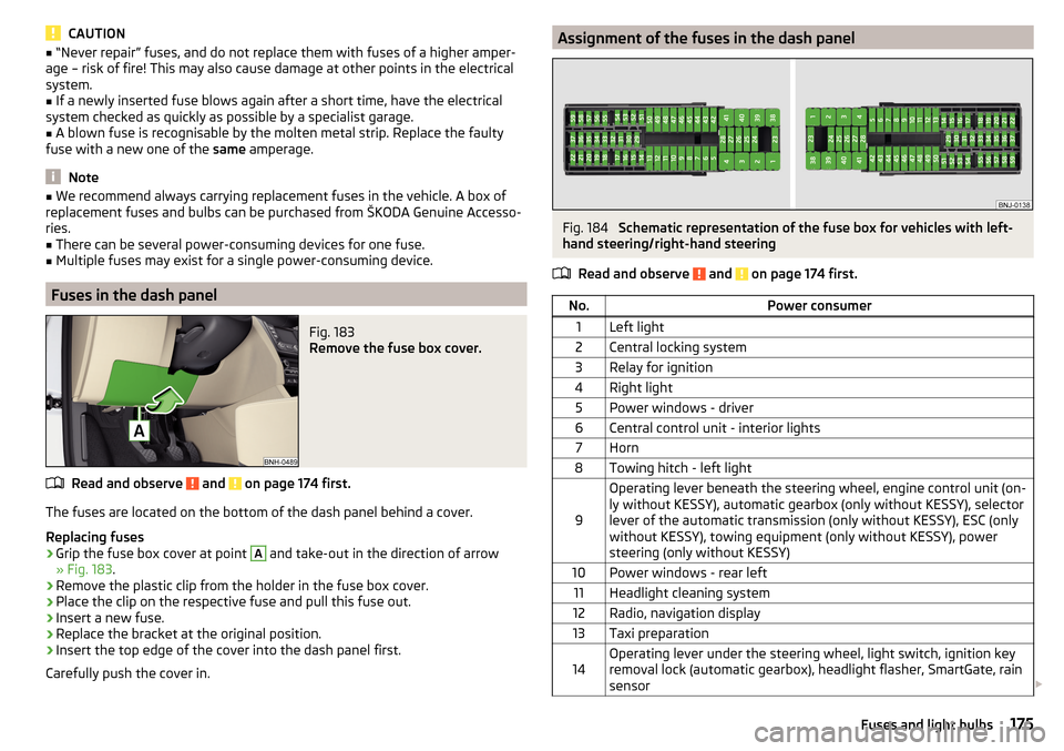
Assignment of the fuses in the dash panelFig. 184
Schematic representation of the fuse box for vehicles with left-
hand steering/right-hand steering
Read and observe
and on page 174 first.
No.Power consumer1Left light2Central locking system3Relay for ignition4Right light5Power windows - driver6Central control unit - interior lights7Horn8Towing hitch - left light
9
Operating lever beneath the steering wheel, engine control unit (on-
ly without KESSY), automatic gearbox (only without KESSY), selector
lever of the automatic transmission (only without KESSY), ESC (only
without KESSY), towing equipment (only without KESSY), power
steering (only without KESSY)10Power windows - rear left11Headlight cleaning system12Radio, navigation display13Taxi preparation14Operating lever under the steering wheel, light switch, ignition key
removal lock (automatic gearbox), headlight flasher, SmartGate, rain
sensor 175Fuses and light bulbs
Page 179 of 208
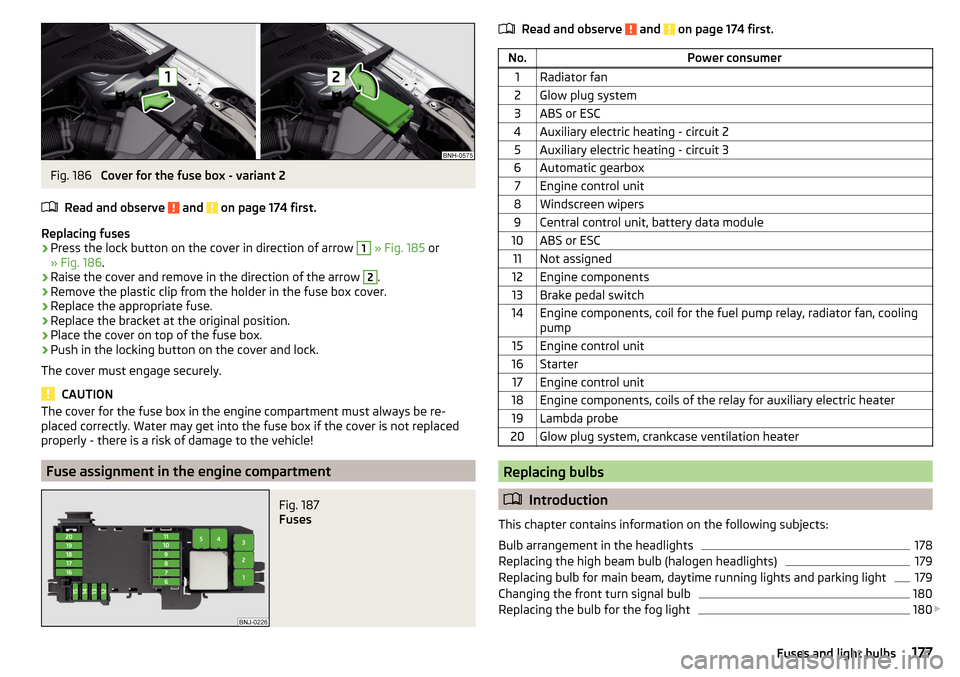
Fig. 186
Cover for the fuse box - variant 2
Read and observe
and on page 174 first.
Replacing fuses
›
Press the lock button on the cover in direction of arrow
1
» Fig. 185 or
» Fig. 186 .
›
Raise the cover and remove in the direction of the arrow
2
.
›
Remove the plastic clip from the holder in the fuse box cover.
›
Replace the appropriate fuse.
›
Replace the bracket at the original position.
›
Place the cover on top of the fuse box.
›
Push in the locking button on the cover and lock.
The cover must engage securely.
CAUTION
The cover for the fuse box in the engine compartment must always be re-
placed correctly. Water may get into the fuse box if the cover is not replaced
properly - there is a risk of damage to the vehicle!
Fuse assignment in the engine compartment
Fig. 187
Fuses
Read and observe and on page 174 first.No.Power consumer1Radiator fan2Glow plug system3ABS or ESC4Auxiliary electric heating - circuit 25Auxiliary electric heating - circuit 36Automatic gearbox7Engine control unit8Windscreen wipers9Central control unit, battery data module10ABS or ESC11Not assigned12Engine components13Brake pedal switch14Engine components, coil for the fuel pump relay, radiator fan, cooling
pump15Engine control unit16Starter17Engine control unit18Engine components, coils of the relay for auxiliary electric heater19Lambda probe20Glow plug system, crankcase ventilation heater
Replacing bulbs
Introduction
This chapter contains information on the following subjects:
Bulb arrangement in the headlights
178
Replacing the high beam bulb (halogen headlights)
179
Replacing bulb for main beam, daytime running lights and parking light
179
Changing the front turn signal bulb
180
Replacing the bulb for the fog light
180
177Fuses and light bulbs