boot SKODA RAPID SPACEBACK 2016 1.G User Guide
[x] Cancel search | Manufacturer: SKODA, Model Year: 2016, Model line: RAPID SPACEBACK, Model: SKODA RAPID SPACEBACK 2016 1.GPages: 184, PDF Size: 28.1 MB
Page 77 of 184

Fig. 85
Adjusting the holder size
Read and observe on page 74 first.
The holder may be tipped by 30° in the direction of the arrow
1
and turned by
360° in the direction of arrow
2
» Fig. 84 .
›
To adjust the holder size , pull out the securing tab
A
in the direction of ar-
row
3
and push the part
B
in the direction of arrow
4
to the desired posi-
tion » Fig. 85 .
Transport of cargo
Luggage compartment and transporting objects
Introduction
This chapter contains information on the following subjects:
Fastening elements
76
Fixing nets
76
Multifunction pocket
77
Hooks
77
Luggage compartment cover
77
“Parking position” of the boot cover
78
Storage compartment in the boot
78
Storage net bag
79
Cargo elements
79
Floor covering on both sides
79
Class N1 vehicles
79
When transporting heavy objects, the driving characteristics change due to the
shift in centre-of-gravity. The speed and style of driving must be adjusted ac-
cordingly.
When transporting cargo the following the instructions must be adhered to
▶ Distribute the load evenly in the luggage compartment and secure it with
suitable lashing straps to the lashing eyes or fixing nets so that they cannot
slip.
▶ Place heavy objects as far forward as possible.
▶ Tyre pressure is to match the load.
In the event of an accident, even small and light objects gain so much kinetic
energy that they can cause severe injuries.
The magnitude of the kinetic energy is dependent on the speed at which the
vehicle is travelling and the weight of the object.
Luggage compartment light
The light switches on/off when the luggage compartment lid is opened or
closed.
If the boot lid is open and the ignition switched off, the light will go out auto-
matically after 10 minutes.
75Transport of cargo
Page 79 of 184

Fig. 88
Fastening a vertical pocket
Read and observe and on page 76 first.
Fastening examples for nets » Fig. 87 and » Fig. 88
Horizontal pocket
Floor net
Vertical pocket
The maximum permissible load of each of the nets is 1.5 kg.
Multifunction pocket
Fig. 89
Securing the multifunction pock-
et
Read and observe and on page 76 first.
The pocket » Fig. 89 can be secured to the fastening elements
A
,
B
and
C
» Fig. 86 on page 76 .
The maximum permissible load for the pocket attached to the fastening ele-
ment is 3 kg.
Note
In vehicles with a variable loading floor, it is not possible to secure the pocket
to the fastening elements.ABCHooksFig. 90
Hooks
Read and observe and on page 76 first.
One hook for attaching small items of luggage, such as bags etc., is provided
on each side of the luggage compartment » Fig. 90.
The maximum permissible load of the hook is 7.5 kg.
Luggage compartment cover
Fig. 91
Remove the luggage compartment cover
Read and observe
and on page 76 first.
If the support straps
A
» Fig. 91 are attached to the boot lid, then opening the
lid will raise the boot lid cover (hereafter referred to as the cover).
The cover may be removed from the vehicle or stowed behind the rear seat
backs in the so-called “park position” » Fig. 92 on page 78 .
The maximum permissible load of the cover is 1 kg.
77Transport of cargo
Page 80 of 184
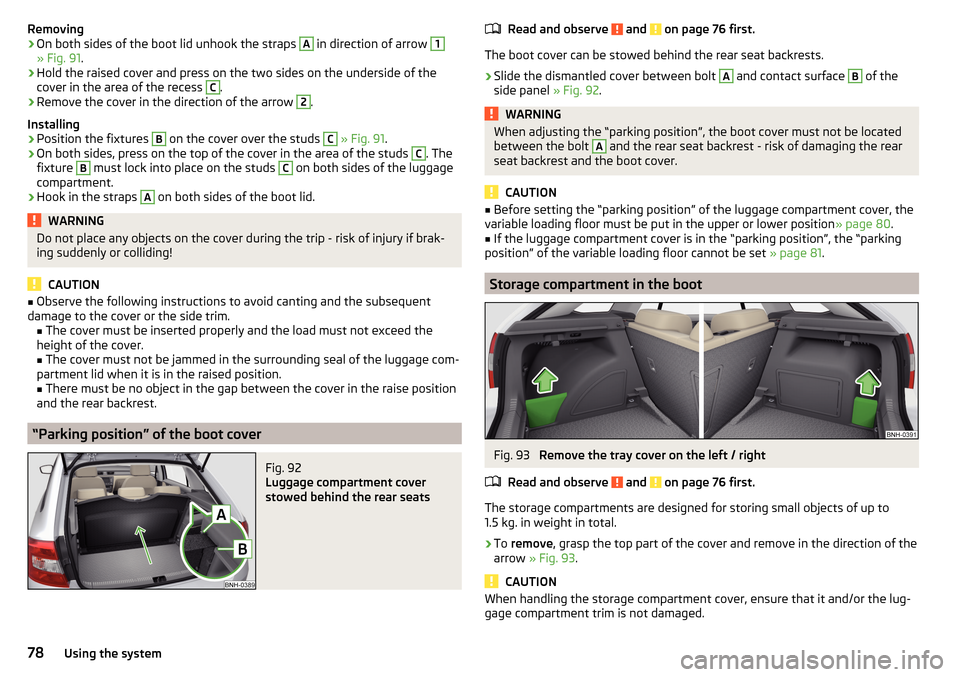
Removing›On both sides of the boot lid unhook the straps A in direction of arrow 1
» Fig. 91.
›
Hold the raised cover and press on the two sides on the underside of the
cover in the area of the recess
C
.
›
Remove the cover in the direction of the arrow
2
.
Installing
›
Position the fixtures
B
on the cover over the studs
C
» Fig. 91 .
›
On both sides, press on the top of the cover in the area of the studs
C
. The
fixture
B
must lock into place on the studs
C
on both sides of the luggage
compartment.
›
Hook in the straps
A
on both sides of the boot lid.
WARNINGDo not place any objects on the cover during the trip - risk of injury if brak-
ing suddenly or colliding!
CAUTION
■ Observe the following instructions to avoid canting and the subsequent
damage to the cover or the side trim. ■ The cover must be inserted properly and the load must not exceed the
height of the cover.
■ The cover must not be jammed in the surrounding seal of the luggage com-
partment lid when it is in the raised position. ■ There must be no object in the gap between the cover in the raise position
and the rear backrest.
“Parking position” of the boot cover
Fig. 92
Luggage compartment cover
stowed behind the rear seats
Read and observe and on page 76 first.
The boot cover can be stowed behind the rear seat backrests.
›
Slide the dismantled cover between bolt
A
and contact surface
B
of the
side panel » Fig. 92.
WARNINGWhen adjusting the “parking position”, the boot cover must not be located
between the bolt A and the rear seat backrest - risk of damaging the rear
seat backrest and the boot cover.
CAUTION
■ Before setting the “parking position” of the luggage compartment cover, the
variable loading floor must be put in the upper or lower position » page 80.■
If the luggage compartment cover is in the “parking position”, the “parking
position” of the variable loading floor cannot be set » page 81.
Storage compartment in the boot
Fig. 93
Remove the tray cover on the left / right
Read and observe
and on page 76 first.
The storage compartments are designed for storing small objects of up to
1.5 kg. in weight in total.
›
To remove , grasp the top part of the cover and remove in the direction of the
arrow » Fig. 93 .
CAUTION
When handling the storage compartment cover, ensure that it and/or the lug-
gage compartment trim is not damaged.78Using the system
Page 81 of 184

Storage net bagFig. 94
Meshed pocket for storage
Read and observe and on page 76 first.
The meshed pocket for storage is located on the right-hand side of the boot» Fig. 94 .
The meshed pocket for storage is designed for storing small objects of up to
1.5 kg. in weight in total.
Cargo elements
Fig. 95
Remove cargo element: Version 1/version 2
Fig. 96
Remove cargo element: Version 3 / Mounting example of the car-
go using the cargo elements
Read and observe
and on page 76 first.
The cargo elements are designed for mounting and securing loads with a max-imum gross weight of 8 kg.
›
To use , remove the cargo elements in the direction of the arrows » Fig. 95
and » Fig. 96
.
›
Use the cargo elements to secure the load as close as possible to the rear
seats » Fig. 96
.
›
After use, secure the cargoelements in their original position.
Floor covering on both sides
Read and observe
and on page 76 first.
You can fit a double-sided floor covering in the luggage compartment. One
side is made of fabric, the other side is washable (suitable for transporting wet
or dirty items).
Class N1 vehicles
Read and observe
and on page 76 first.
In class N1 vehicles that are not fitted with a protective grille, a lashing set that
complies with the EN 12195 standard (1 - 4) must be used for fastening the
load.
79Transport of cargo
Page 83 of 184
CAUTIONWhen removing or inserting the variable loading floor, a distance of 15 cm B» Fig. 98 underneath the edge of the cover must be maintained - risk of dam-
aging the boot lid seal.
Note
The variable loading floor cannot be placed in the vehicle when the luggage
compartment cover is in the “park position” » page 78.
Folding up/down, “parking position”
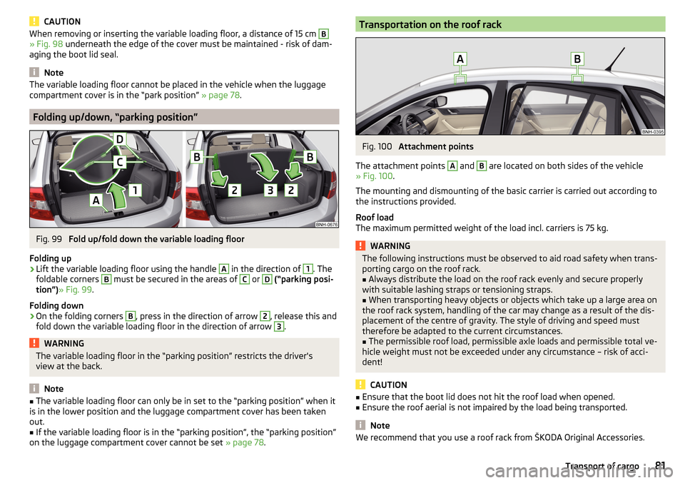
Fig. 99
Fold up/fold down the variable loading floor
Folding up
›
Lift the variable loading floor using the handle
A
in the direction of
1
. The
foldable corners
B
must be secured in the areas of
C
or
D
(“parking posi-
tion”) » Fig. 99 .
Folding down
›
On the folding corners
B
, press in the direction of arrow
2
, release this and
fold down the variable loading floor in the direction of arrow
3
.
WARNINGThe variable loading floor in the “parking position” restricts the driver's
view at the back.
Note
■ The variable loading floor can only be in set to the “parking position” when it
is in the lower position and the luggage compartment cover has been taken
out.■
If the variable loading floor is in the “parking position”, the “parking position”
on the luggage compartment cover cannot be set » page 78.
Transportation on the roof rackFig. 100
Attachment points
The attachment points
A
and
B
are located on both sides of the vehicle
» Fig. 100 .
The mounting and dismounting of the basic carrier is carried out according to
the instructions provided.
Roof load
The maximum permitted weight of the load incl. carriers is 75 kg.
WARNINGThe following instructions must be observed to aid road safety when trans- porting cargo on the roof rack.■
Always distribute the load on the roof rack evenly and secure properly
with suitable lashing straps or tensioning straps.
■
When transporting heavy objects or objects which take up a large area on
the roof rack system, handling of the car may change as a result of the dis-
placement of the centre of gravity. The style of driving and speed must
therefore be adapted to the current circumstances.
■
The permissible roof load, permissible axle loads and permissible total ve-
hicle weight must not be exceeded under any circumstance – risk of acci-
dent!
CAUTION
■ Ensure that the boot lid does not hit the roof load when opened.■Ensure the roof aerial is not impaired by the load being transported.
Note
We recommend that you use a roof rack from ŠKODA Original Accessories.81Transport of cargo
Page 104 of 184
OperationFig. 121
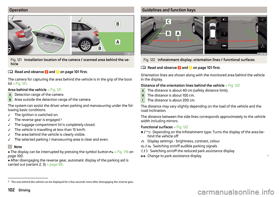
Installation location of the camera / scanned area behind the ve-
hicle
Read and observe
and on page 101 first.
The camera for capturing the area behind the vehicle is in the grip of the bootlid » Fig. 121 .
Area behind the vehicle » Fig. 121
Detection range of the camera
Area outside the detection range of the camera
The system can assist the driver when parking and manoeuvring under the fol- lowing basic conditions.
The ignition is switched on.
The reverse gear is engaged. 1)
The luggage compartment lid is completely closed.
The vehicle is travelling at less than 15 km/h.
The area behind the vehicle is clearly visible.
The selected parking / manoeuvring area is clear and even.
Note
■ The display can be interrupted by pressing the symbol button » Fig. 119 on
page 100 .■
After disengaging the reverse gear, automatic display of the parking aid is
carried out (variant 2, 3) » page 99.
ABGuidelines and function keysFig. 122
Infotainment display: orientation lines / functional surfaces
Read and observe
and on page 101 first.
Orientation lines are shown along with the monitored area behind the vehicle
in the display.
Distance of the orientation lines behind the vehicle » Fig. 122
The distance is about 40 cm (safety distance limit).
The distance is about 100 cm.
The distance is about 200 cm.
The distance may vary slightly depending on the load of the vehicle and the
road inclination.
The distance between the side lines corresponds approximately to the vehicle
width including mirrors.
Functional surfaces » Fig. 122
Depending on the Infotainment type: Turns the display of the area be-
hind the vehicle off
Display settings - brightness, contrast, colour Switching on/off audible parking signals
Switching on/off the reduced park assistance display
Change to park assistance display
ABC
1)
The area behind the vehicle can be displayed for a few seconds more after disengaging the reverse gear.
102Driving
Page 117 of 184
›Remove the tow bar from the mounting recess downwards and in the direc-
tion of the arrow 3. At the same time, the ball rod latches into the ready po-
sition and is therefore ready to be re-fitted.
After removing the ball rod, insert the cap for the receiving shaft A
against
the direction of arrow
1
» Fig. 139 on page 113 .
If the hand wheel
A
is not turned all the way to the stop, then it will return to
its initial position when the tow bar is removed and will rest on the tow bar
and not engage into the ready position. The ball head then needs to be
brought into this position before the next time it is fitted » page 112, Adjusting
the ready position .
The ball rod must be cleaned before storing in the box with the vehicle tool
always.
WARNINGNever allow the tow bar to remain unsecured in the boot. This could cause
damage to the boot upon sudden braking, and could put the safety of the
occupants at risk.
Vertical load with mounted accessories
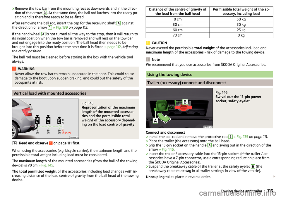
Fig. 145
Representation of the maximum
length of the mounted accesso-
ries and the permissible total
weight of the accessory depend-
ing on the load centre of gravity
Read and observe on page 111 first.
When using the accessories (e.g. bicycle carrier), the maximum length and the
permissible total weight including load must be considered.
The maximum length of the mounted accessories (from the ball of the towing
device) is 70 cm » Fig. 145 .
The total permitted weight of the accessories including load changes with in-
creasing distance of the load centre of gravity from the ball head of the towing
device.
Distance of the centre of gravity of the load from the ball headPermissible total weight of the ac- cessory, including load0 cm50 kg30 cm50 kg60 cm25 kg70 cm0 kg
CAUTION
Never exceed the permissible total weight of the accessories incl. load and
maximum length of the accessories - risk of damage to the towing device.
Note
We recommend that you use accessories from ŠKODA Original Accessories.
Using the towing device
Trailer (accessory) connect and disconnect
Fig. 146
Swivel out the 13-pin power
socket, safety eyelet
Connect and disconnect
›
Install the ball rod and remove the protective cap
3
» Fig. 135 on page 111 .
›
Place the trailer (the accessory) onto the ball head.
›
Grip the 13-pin socket on the handle
A
and swing out in the direction of the
arrow » Fig. 146 .
›
Insert the trailer / accessory cable into the 13-pin socket. (If the trailer / ac-
cessories have a 7-pin connector, use a corresponding reduction piece from
the ŠKODA Original Accessories).
›
Suspend the breakaway cable of the trailer at the safety eyelet
B
(the
breakaway cable must sag in all trailer settings in view of the vehicle).
Uncoupling takes place in reverse order.
115Towing device and trailer
Page 121 of 184
ŠKODA Original partsRead and observe
on page 118 first.
We recommend the use of ŠKODA Genuine Parts for your vehicle, as these
parts are approved by ŠKODA AUTO. These parts comply wholly with ŠKODA
AUTO regulations and are identical to the parts used in series production.
ŠKODA AUTO is able to warrant the safety, suitability, and long life of these
products.
ŠKODA Service Partners are liable for any defects of ŠKODA Genuine Parts for
a period of 2 years after sale in accordance with the materials defect liability,
unless agreed otherwise in the purchase agreement.
ŠKODA Original accessories
Read and observe
on page 118 first.
If you wish to fit accessories to your vehicle, you should remember the follow-
ing.
We recommend that you use ŠKODA Genuine Accessories in your vehicle.
ŠKODA AUTO has selected these accessories to ensure that they are reliable,
safe and suitable for your particular vehicle. Although we constantly monitor
the market, we are not able to assess or vouch the suitability of other products
for your vehicle, despite the fact that some products may have operational ap-
proval or may have been approved by a nationally recognised testing laborato-
ry.
ŠKODA Service Partners are liable for any defects of ŠKODA Genuine Accesso-
ries for a period of 2 years after installation or delivery in accordance with the
materials defect liability, unless agreed otherwise in the purchase agreement
or any other agreements.
Spoiler
Read and observe
on page 118 first.
WARNINGIf your vehicle is equipped with a Genuine Accessories spoiler on the front
bumper in combination with the spoiler on the boot lid, the following in-
structions must be observed - otherwise there is a risk of accidents and se-
rious injuries!■
The vehicle can only be equipped with a spoiler on the front bumper in
combination with the corresponding spoiler on the boot lid.
■
A Genuine Accessories spoiler cannot be fitted to the front bumper either
on its own (without a spoiler on the boot lid) or in combination with an un-
suitable spoiler on the boot lid.
■
We recommend that you consult the ŠKODA Service Partner for any re-
pairs to or replacement, addition or removal of spoilers.
■
Unprofessional work carried out on the spoilers of your vehicle may result
in some functions/vehicle systems malfunctioning.
Component protection
Read and observe
on page 118 first.
Some electronic vehicle components (such as the instrument cluster) are fac-
tory-equipped with component protection. This ensures the functional limita-
tion of these components in a non-legitimate installation in another vehicle
(e.g. after a theft) or operation outside the vehicle.
Airbags
Read and observe
on page 118 first.
WARNING■Modifications, repairs and technical alterations that have been carried out
unprofessionally can cause damage and operational faults, and can also se-
riously impair the effectiveness of the airbag system – risk of accident and
fatal injury!■
A change to the vehicle's wheel suspension, including the use of non-ap-
proved wheels and tire combinations, can impair the functioning of the air-
bag system - risk of accident and fatal injury!
119Care and maintenance
Page 142 of 184

Do-it-yourself
Emergency equipment and self-help
Emergency equipment
Introduction
This chapter contains information on the following subjects:
Placement of the first aid kit and warning triangle
140
Location of reflective vest
140
fire extinguisher
140
Vehicle tool kit
141
Placement of the first aid kit and warning triangle
Fig. 160
Placing of the first-aid kit and the warning triangle
The following information is for the first aid kit and warning triangle from the
ŠKODA Original accessories valid.
Placing the first-aid kit
The first-aid box can be attached by a strap to the right-hand side of the boot
» Fig. 160 .
Placing of the warning triangle - variant 1
The warning triangle can be inserted into the recess under the loading edge
and secured with the fastener tape » Fig. 160 -
.
Placing of the warning triangle - variant 2
On vehicles with the vehicle battery in the boot warning triangle can be stow-
ed in a box under the floor covering in the luggage compartment » Fig. 160 -
.
WARNINGProperly secure the first aid kit and the warning triangle - there is a risk of
injury in the event of sudden braking or a vehicle collision.
Location of reflective vest
Fig. 161
Storage compartment for the re-
flective vest
The reflective vest can be stored in a bracket under the driver's seat » Fig. 161.
fire extinguisher
Fig. 162
Release the fire extinguisher
The fire extinguisher is attached by two straps in a holder underneath the driv-
er's seat.
›
To remove the fire extinguisher, release the safety catches on the two belts
in the direction of arrow » Fig. 162 and remove the fire extinguisher.
›
To secure , place the fire extinguisher back in the mount and secure with the
belts.
The Owner´s Manual is fitted next to the fire extinguisher.
Pay attention to the expiration date of the fire extinguisher. After this date,
the correct function of the device is not guaranteed.
140Do-it-yourself
Page 144 of 184

›Jack up the vehicle
» page 144 until the wheel that needs changing is clear of
the ground.›
Unscrew the wheel bolts and place them on a clean surface (cloth, paper,
etc.).
›
Remove the wheel carefully.
›
Attach the spare wheel and slightly screw on the wheel bolts.
›
Lower the vehicle.
›
Tighten the wheel bolts opposite each other using the wheel wrench (“pull- ing crossways”) » page 144.
›
Replace the wheel trim » page 143 and caps » page 143 .
When fitting unidirectional tyres, ensure that the direction of rotation is cor-
rect » page 136 .
All bolts must be clean and must turn easily. If screws are corroded and diffi-
cult to move, these must be replaced.
WARNING■ Undo the wheel bolts just a little (about one turn), provided the vehicle
has not yet been jacked up. Otherwise the wheel could come loose and fall
off – risk of injury.■
Under no circumstances must the bolts be greased or oiled - cause an ac-
cident.
Subsequent steps
After changing the wheel, the following work must be carried out.
›
Stow the replaced wheel in the well under the floor covering of the luggage
compartment and secure it with a nut.
›
Stow the tool kit in the space provided and secure using the band.
›
Check tyre pressure on the mounted wheel and adjust if necessary and, with
vehicles with tyre pressure monitoring, save the tyre pressure values in the
system » page 109 .
›
Have the tightening torque of the wheel bolts checked as soon as possible.
The prescribed tightening torque is 120 Nm.
Replace the damaged wheel or consult a specialist garage about repair op-
tions.
WARNINGTightening torque which is too high can damage the threads and this can
result in permanent deformation of the contact surfaces on the rim. Where
tightening torque is too low, the wheels may become loose while driving -
risk of accident. Therefore drive cautiously and only at a moderate speed
until the tightening torque has been checked.
Removing/stowing the emergency or spare wheel
Fig. 164
Take out the wheel
The wheel is located in a well under the floor covering in the luggage compart-
ment and is fixed in place with a screw.
Take out the wheel
›
Lift up the floor in the luggage compartment.
›
Loosen the retaining belt and take out the box with the tool kit.
›
Unscrew the nut in the direction of arrow » Fig. 164 and take out the wheel.
Stow the wheel
›
Place the wheel into the wheel well with the wheel rim pointing downward.
On vehicles with the vehicle battery in the boot, lay down the wheel with the
outer face upward.
›
Pull the fixing band through the opposite holes in the wheel rim.
›
Screw the nut in the opposite direction to the arrow until it stops » Fig. 164.
›
Place the box with the tool kit back inside the wheel and secure it with the
tape.
›
Fold back the floor in the luggage compartment.
142Do-it-yourself