Break light SKODA RAPID SPACEBACK 2016 1.G Owner's Manual
[x] Cancel search | Manufacturer: SKODA, Model Year: 2016, Model line: RAPID SPACEBACK, Model: SKODA RAPID SPACEBACK 2016 1.GPages: 184, PDF Size: 28.1 MB
Page 5 of 184
Brake fluid133Vehicle battery133
Wheels
136
Wheels and tyres
136
Operating in winter conditions
139
Do-it-yourself
Emergency equipment and self-help
140
Emergency equipment
140
Changing a wheel
141
Breakdown kit
145
Jump-starting
147
Towing the vehicle
148
Remote - change battery
150
Emergency unlocking / unlocking of doors
150
Replacing windscreen wiper blades
151
Fuses and light bulbs
153
Fuses
153
Bulbs
156
Technical data
Technical data
162
Basic vehicle data
162
Vehicle-specific details per engine type
167
Index
3Table of Contents
Page 12 of 184

Safety
Passive Safety
General information
Introduction
This chapter contains information on the following subjects:
Before setting off
10
Driving safety
10
In this section of the instructions you will find important information on the
subject of passive safety. We have combined everything here which you
should be familiar with, for example, regarding seat belts, airbags, safety of children and anything similar.
Other important safety information can also be found in the subsequent sec-
tions of this Owner's Manual. The Owner's Manual should therefore always be
kept in the vehicle.
Before setting off
For your own safety and the safety of the people travelling with you, please
pay attention to the following points before setting off.
▶ Check the lights and turn signal lights are functioning correctly.
▶ Check the wiper function and the wiper blades for wear. Check the wind-
screen washer fluid level.
▶ Ensure that all of the windows offer good visibility to the outside.
▶ Adjust the rear-view mirror so that vision to the rear is guaranteed. Ensure
that the mirrors are not covered.
▶ Check the tyre inflation pressure.
▶ Check the engine oil, brake fluid and coolant level.
▶ Secure all items of luggage.
▶ Do not exceed the permissible axle loads and permissible gross weight of the
vehicle.
▶ Close all doors as well as the bonnet and boot lid.
▶ Ensure that no objects can obstruct the pedals.
▶
Protect children using a suitable child seat » page 19, Transporting children
safely .
▶ Adopt the correct seated position. Tell your passengers to assume the cor-
rect seated position » page 10, Correct and safe seated position .
Driving safety
For safety in traffic, the following precautions must be observed. ▶ Do not become distracted from concentrating on the traffic situation, (e.g. by
your passengers or mobile phone calls).
▶ Never drive when your driving ability is impaired, (e.g. due to medication, al-
cohol, drugs or similar).
▶ Keep to the traffic regulations and the permissible speed limit.
▶ Always adjust the driving speed to the road, traffic and weather conditions.
▶ Take regular breaks on long journeys (at least every two hours).
Correct and safe seated position
Introduction
This chapter contains information on the following subjects:
The correct seating position for the driver
11
Adjusting the steering wheel position
11
Correct seating position for the front passenger
12
Correct seating position for the passengers in the rear seats
12
Always assume the correct seated position before setting off and do not
change this position while driving. Also advise your passengers to adopt the
correct seated position and not to change this position while the car is moving.
The following list contains instructions for the Passenger which, if not ob-
served, may cause serious injuries or death. ▶ Do not lean against the dash panel.
▶ Do not put your feet on the dash panel.
The following list contains instructions for all Passengers which, if not ob-
served, may cause serious injuries or death.
▶ Do not sit only on the front part of the seat.
▶ Do not sit facing to one side.
▶ Do not lean out of the window.
▶ Do not put your limbs out of the window.
▶ Do not put your feet on the seat cushion.
10Safety
Page 50 of 184
SafeLockRead and observe
and on page 46 first.
SafeLock prevents opening the doors from inside as well as window operation.
This makes an attempted break-in to the vehicle more difficult.
Activating
SafeLock is activated when the vehicle is locked from the outside.
This function is pointed out by the following message on the display of the in-
strument cluster after the ignition is switched off.
Check SAFELOCK! Log book!CHECK SAFELOCK
Activation display
When SafeLock is activated, the warning light in the driver's door flashes for 2
seconds in rapid succession, then starts to flash at longer intervals.
Deactivating
▶ By locking twice within 2 seconds.
▶ or: by deactivating the interior monitor and the towing protection
» page 50 .
The warning light in the driver door flashes rapidly for about 2 seconds, then
goes out and starts to flash at longer intervals after about 30 seconds.
If the vehicle is locked and the safe securing system is switched off, the door
can be opened separately from the inside by a single pull on opening lever.
The SafeLock switches on the next time the vehicle is locked.
WARNINGIf the car is locked and the safe securing system activated, no people must
remain in the car as it will then not be possible to either unlock a door or
open a window from the inside. The locked doors make it more difficult for
rescuers to get into the vehicle in an emergency – risk to life!
Individual settings
Read and observe
and on page 46 first.
The following functions of the central locking system can be set individually in
Infotainment » Owner´s Manual - Infotainment .
All doors
The function allows you to unlock all doors, the boot lid and the fuel filler flap.
Single door
The function allows you to unlock only the driver's door and the fuel filler flap
with the radio remote control. KESSY allows the unlocking of a single door
which is in the vicinity of the key, as well as the fuel filler flap. The other doors
and the boot lid are only unlocked once the door handle is unlocked or
touched.
Doors on a vehicle side
This function enables you to unlock both doors on the driver's side and the
fuel filler flap with the radio remote control unit. KESSY allows the unlocking of
both doors which are in the vicinity of the key, as well as the fuel filler flap. The
other doors and the boot lid are only unlocked once the door handle is un-
locked or touched.
Automatic locking/unlocking
This function enables the locking of all doors and the boot lid from a speed of
15 km / h. Opening the doors and the boot lid from the outside is not possible.
The renewed unlocking of the doors and the boot lid is carried out when the
ignition key is removed or when the door is opened from inside (depending on
the individual setting for the central locking system).
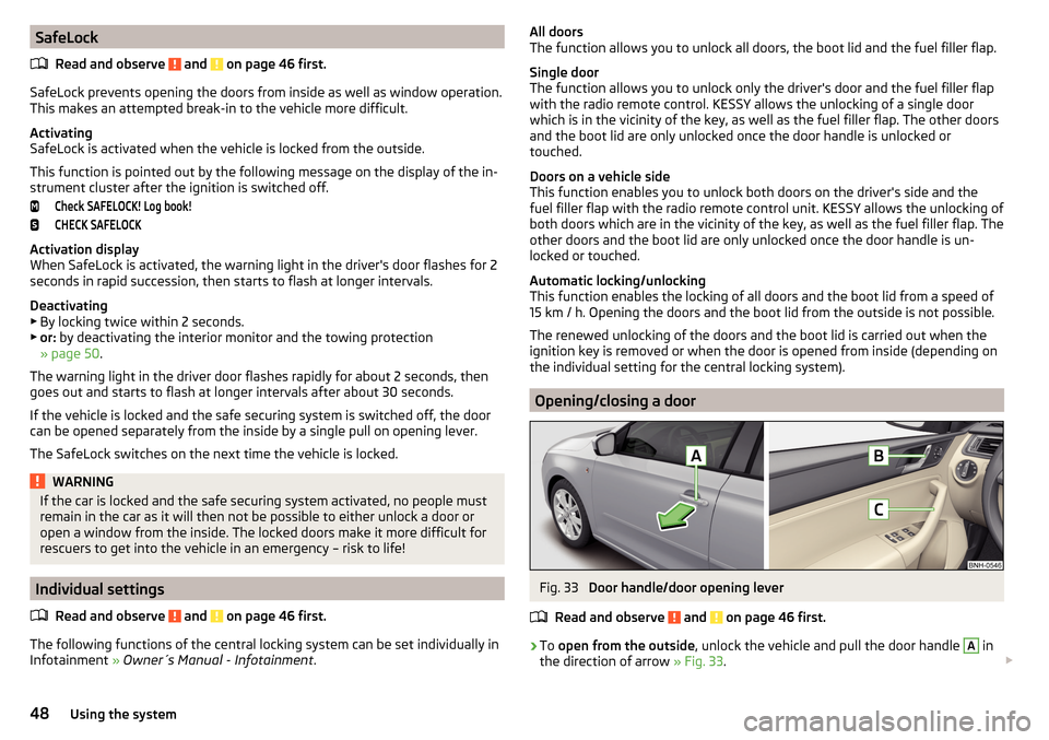
Opening/closing a door
Fig. 33
Door handle/door opening lever
Read and observe
and on page 46 first.
›
To open from the outside , unlock the vehicle and pull the door handle
A
in
the direction of arrow » Fig. 33.
48Using the system
Page 51 of 184
›To
open from the inside pull the door opening lever B and push the door
away from you.›
To the lock from the inside , grab the handle
C
and close the door.
WARNING■
The door must be closed properly, otherwise it could open whilst the ve-
hicle is in motion - risk of fatality!■
Only open and close the door when there is no one in the opening/closing
range – risk of injury!
■
Never drive with the doors open - there is a risk of death!
■
An opened door can close automatically if there is a strong wind or the
vehicle is on an incline – risk of injury!
Child safety lock
Fig. 34
Rear door: Child safety system switch on / off
Read and observe
and on page 46 first.
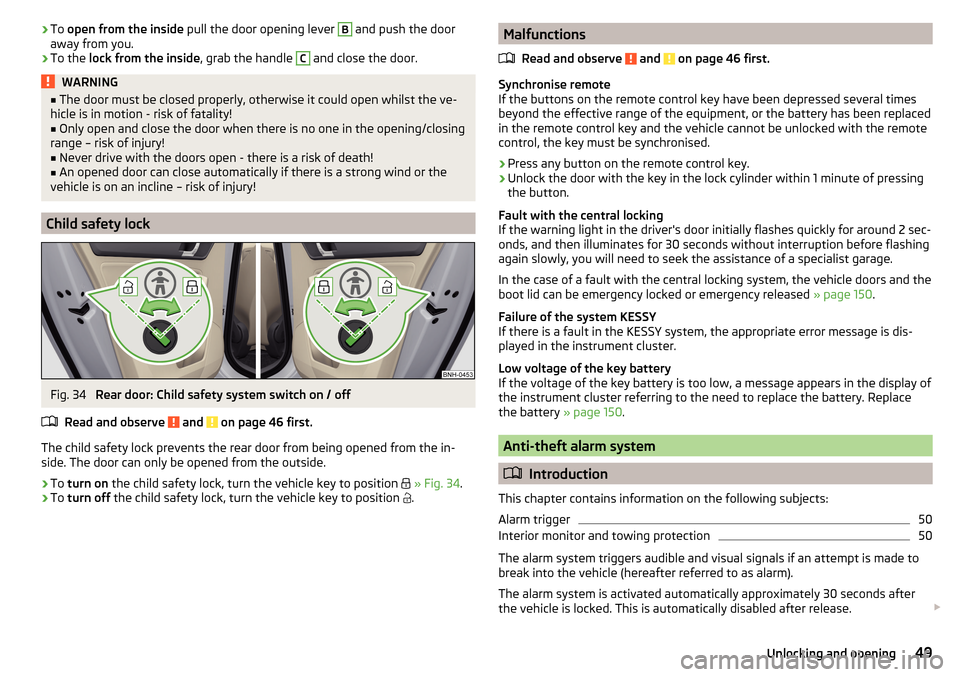
The child safety lock prevents the rear door from being opened from the in-
side. The door can only be opened from the outside.
›
To turn on the child safety lock, turn the vehicle key to position
» Fig. 34 .
›
To turn off the child safety lock, turn the vehicle key to position
.
Malfunctions
Read and observe
and on page 46 first.
Synchronise remote
If the buttons on the remote control key have been depressed several times
beyond the effective range of the equipment, or the battery has been replaced
in the remote control key and the vehicle cannot be unlocked with the remote
control, the key must be synchronised.
›
Press any button on the remote control key.
›
Unlock the door with the key in the lock cylinder within 1 minute of pressing the button.
Fault with the central locking
If the warning light in the driver's door initially flashes quickly for around 2 sec-
onds, and then illuminates for 30 seconds without interruption before flashing
again slowly, you will need to seek the assistance of a specialist garage.
In the case of a fault with the central locking system, the vehicle doors and the
boot lid can be emergency locked or emergency released » page 150.
Failure of the system KESSY
If there is a fault in the KESSY system, the appropriate error message is dis-
played in the instrument cluster.
Low voltage of the key battery
If the voltage of the key battery is too low, a message appears in the display of the instrument cluster referring to the need to replace the battery. Replace
the battery » page 150.
Anti-theft alarm system
Introduction
This chapter contains information on the following subjects:
Alarm trigger
50
Interior monitor and towing protection
50
The alarm system triggers audible and visual signals if an attempt is made to
break into the vehicle (hereafter referred to as alarm).
The alarm system is activated automatically approximately 30 seconds after the vehicle is locked. This is automatically disabled after release.
49Unlocking and opening
Page 68 of 184
›To
remove , hold the locking button A in the direction of arrow 1, at the
same time, using a flat screwdriver (with a max. width of 5 mm), press the
locking button in the opening B
in the direction of arrow
2
and remove the
rest in the direction of arrow
3
» Fig. 60 .
›
To insert the headrest, push the headrest into the seat backrest in the direc-
tion of arrow
4
until the locking button clicks into place.
Seat heaters
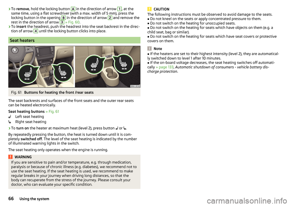
Fig. 61
Buttons for heating the front /rear seats
The seat backrests and surfaces of the front seats and the outer rear seats
can be heated electronically.
Seat heating buttons » Fig. 61
Left seat heating
Right seat heating
›
To turn on the heater at maximum heat (level 2), press button
or
.
By repeatedly pressing the button, the heat is turned down until it is com-
pletely switched off . The level of the seat heating is indicated by the number
of illuminated warning lights in the switch.
The seat heating only operates when the engine is running.
WARNINGIf you are sensitive to pain and/or temperature, e.g. through medication,
paralysis or because of chronic illness (e.g. diabetes), we recommend not to
use the seat heating. If the seat heating is used, we recommend to make
regular breaks in your journey when driving long distances, so that the
body can recuperate from the stress of the journey. Please consult your
doctor, who can evaluate your specific condition.CAUTIONThe following instructions must be observed to avoid damage to the seats.■Do not kneel on the seats or apply concentrated pressure to them.■
Do not switch on the heating for unoccupied seats.
■
Do not switch on the heating for seats which have objects on them (e.g. a
child seat, bag or similar).
■
Do not switch on the heating for seats which have seat covers or protective
covers on them.
Note
■ If the heaters are set to their highest intensity (level 2), they are automatical-
ly switched down to level 1 after 10 minutes.■
If the on-board voltage decreases, the seat heating switches off automati-
cally » page 133 , Automatic shutdown of consumers - vehicle battery dis-
charge protection .
66Using the system
Page 111 of 184
If none of these conditions are met or if the driving style is not changed, the
system recommends a driving break again after 15 minutes.
The system can be activated/deactivated in Infotainment » Owner´s Manual -
Infotainment .
Pause recommendation
The icon appears and the following message for a few seconds in the display
of the instrument cluster and a message about the detected fatigue. An au-
dible signal is also emitted.WARNING■ The general information relating to the use of assistance systems must
be observed » page 96, in section Introduction .■
For the driving ability is always the driver's responsibility. Never drive if
you feel tired.
■
The system may not detect all cases where a break is needed.
■
Therefore, take regular, sufficient breaks during long trips.
■
There will be no system warning during the so-called micro-sleep.
Note
■ In some situations, the system may evaluate the driving incorrectly and thus
mistakenly recommend a break (e.g. sporty driving, adverse weather condi-
tions or poor road conditions).■
The system is designed primarily for use on motorways.
Tyre pressure monitoring
Introduction
This chapter contains information on the following subjects:
Storing the tyre pressure values
109
Storing the tyre pressure values and Infotainment display
110
Storing the tyre pressure values by means of the button
110
The tyre pressure monitoring function (hereinafter referred to as the system)
monitors the tyre pressure while driving.
If the tyre inflation pressure changes, the warning light
lights up in the in-
strument cluster and an audible signal is heard » page 33,
Tyre pressure .
The system can only function properly if the tyres have the prescribed inflation
pressure and this pressure values are stored in the system.
WARNING■ The general information relating to the use of assistance systems must
be observed » page 96, in section Introduction .■
Having the correct tyre inflation pressure is always the driver's responsi-
bility. Tyre pressure should be checked regularly » page 137.
■
The system cannot warn in case of very rapid tyre inflation pressure loss,
e.g. in case of sudden tyre damage.
Storing the tyre pressure values
Read and observe
on page 109 first.
The tyre pressure values are always stored in the system, if one of the fol-
lowing events occurs. ▶ Change of tyre inflation pressure.
▶ Change one or more wheels.
▶ Change in position of a wheel on the vehicle.
▶ The warning light in the instrument cluster.
The storage of the tyre pressure values depends on equipment, either in the
infotainment or by pressing a button.
WARNINGBefore storing the pressures, the tyres must be inflated to the specified in-
flation pressure » page 137. When storing incorrect pressure values, the
system could possibly not issue any warnings, even with a too low tyre
pressure.
CAUTION
The tyre pressure values are to be saved every 10,000 km or once annually to
ensure correct system functioning.109Assist systems
Page 143 of 184
WARNINGAlways properly secure the fire extinguisher - there is a risk of injury in the
event of sudden braking or a vehicle collision.
Vehicle tool kit
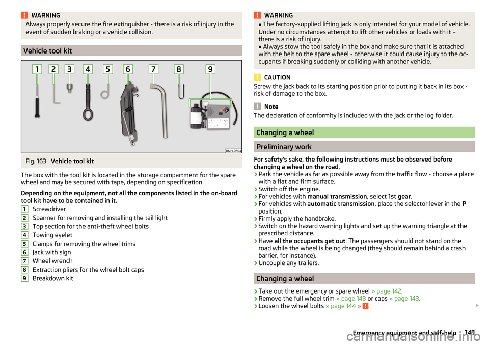
Fig. 163
Vehicle tool kit
The box with the tool kit is located in the storage compartment for the spare
wheel and may be secured with tape, depending on specification.
Depending on the equipment, not all the components listed in the on-board
tool kit have to be contained in it.
Screwdriver
Spanner for removing and installing the tail light
Top section for the anti-theft wheel bolts
Towing eyelet
Clamps for removing the wheel trims
Jack with sign
Wheel wrench
Extraction pliers for the wheel bolt caps
Breakdown kit
123456789WARNING■ The factory-supplied lifting jack is only intended for your model of vehicle.
Under no circumstances attempt to lift other vehicles or loads with it –
there is a risk of injury.■
Always stow the tool safely in the box and make sure that it is attached
with the belt to the spare wheel - otherwise it could cause injury to the oc-
cupants if breaking suddenly or colliding with another vehicle.
CAUTION
Screw the jack back to its starting position prior to putting it back in its box -
risk of damage to the box.
Note
The declaration of conformity is included with the jack or the log folder.
Changing a wheel
Preliminary work
For safety's sake, the following instructions must be observed before
changing a wheel on the road.
›
Park the vehicle as far as possible away from the traffic flow - choose a place
with a flat and firm surface.
›
Switch off the engine.
›
For vehicles with manual transmission , select 1st gear .
›
For vehicles with automatic transmission , place the selector lever in the P
position.
›
Firmly apply the handbrake.
›
Switch on the hazard warning lights and set up the warning triangle at the
prescribed distance.
›
Have all the occupants get out . The passengers should not stand on the
road while the wheel is being changed (they should remain behind a crash
barrier, for instance).
›
Uncouple any trailers.
Changing a wheel
›
Take out the emergency or spare wheel » page 142.
›
Remove the full wheel trim » page 143 or caps » page 143 .
›
Loosen the wheel bolts » page 144 » .
141Emergency equipment and self-help
Page 148 of 184
Preparing to use the breakdown kitRead and observe
on page 145 first.
For safety's sake, the following instructions must be observed before
undertaking a wheel repair on a road.
›
Park the vehicle as far as possible away from the traffic flow - choose a place
with a flat and firm surface.
›
Switch off the engine.
›
For vehicles with manual transmission , select 1st gear .
›
For vehicles with automatic transmission , place the selector lever in the P
position.
›
Firmly apply the handbrake.
›
Switch on the hazard warning lights and set up the warning triangle at the
prescribed distance.
›
Have all the occupants get out . While the repair is being carried out, the pas-
sengers should not stand on the road (instead they should remain behind a
crash barrier, for instance).
›
Uncouple any trailers.
Sealing and inflating tyres
Read and observe
on page 145 first.
Sealing
›
Unscrew the valve cap from the damaged tyre.
›
Insert the valve remover
2
» Fig. 170 on page 145 on the valve insert, so that
the valve insert fits into the slot of the valve remover.
›
Unscrew the valve insert and place it on a clean base (rag, paper etc.).
›
Forcefully shake bottle
10
» Fig. 170 on page 145 several times.
›
Firmly screw the inflation hose
3
onto the tyre inflater bottle
10
. The film on
the bottle cap is pierced.
›
Remove the plug from the inflation hose
3
and insert the bottle onto the
tyre valve.
›
Hold the bottle
10
with the bottom facing upwards and fill all of the sealing
agent from the tyre inflater bottle into the tyre.
›
Remove the filler plug from the tyre valve.
›
Screw in the valve insert with the valve remover
2
.
Inflating
›
Screw the tyre inflation hose
7
» Fig. 170 on page 145 firmly onto the tyre
valve.
› For vehicles with
manual transmission , set the lever in the neutral position.›On vehicles with automatic transmission , place the selector lever in the P
position.›
Start the engine.
›
Plug the connector
6
into the 12-volt socket » page 71.
›
Switch on the air compressor with the ON and OFF switch
9
.
›
Once tyre inflation pressure of 2.0-2.5 bar has been reached, turn off the air
compressor. Maximum run time of 6 minutes » .
›
If you cannot reach an air pressure of 2.0 - 2.5 bar, unscrew the tyre inflation
hose
7
from the tyre valve.
›
Drive the vehicle 10 metres forwards or backwards to allow the sealing agent
to “distribute” in the tyre.
›
Firmly screw the tyre inflation hose
7
back onto the tyre valve and repeat
the inflation process.
›
Stick the sticker
1
» Fig. 170 on page 145 on the dashboard in the driver's
field of view.
At a tyre inflation pressure of 2.0 – 2.5 bar, the journey can be continued at a
maximum speed of 80 km/h or 50 mph.
WARNING■ If the tire does not inflate at least. 2.0 bar, the damage is too great. The
sealing agent cannot be used to seal the tyre. Stop driving! Seek help
from a specialist garage.■
The tyre inflation hose and air compressor may get hot as the tyre is be-
ing inflated – there is a risk of burning.
CAUTION
Switch off the air compressor if it has been running for as much as 6 minutes –
risk of damage to the compressor! Allow the air compressor to cool a few mi-
nutes before switching it on again.
Information on driving with repaired tyres
Read and observe
on page 145 first.
The inflation pressure of the repaired tyre must be checked after driving for 10minutes.
If the tyre pressure is 1.3 bar or less
›
The tyre cannot be properly sealed with the breakdown kit.
Do not contin-
ue to drive! Seek help from a specialist garage.
146Do-it-yourself
Page 151 of 184
›If it is not possible to start the engine, switch on the ignition so that the
steering wheel does not lock and so that the turn signal lights, windscreen
wipers and windscreen washer system can be used.›
Take the vehicle out of gear or move the selector lever into position N if the
vehicle is fitted with an automatic gearbox.
›
Keep the tow rope taut at all times during the towing procedure.
WARNING■ Spiral tow ropes must not be used for towing » Fig. 173- , the towing
eye may unscrew out of the vehicle - risk of accident.■
The tow rope should not be twisted - there is a risk of accidents.
CAUTION
■ Do not tow-start the engine – risk of damaging the engine! The battery from
another vehicle can be used as a jump-start aid » page 147, Jump-starting .■
For off-road towing manoeuvres, there is a risk to both vehicles that the fas-
teners may become overloaded and damaged.
Note
We recommend that you use a tow rope from ŠKODA Original Accessories.
Front towing eye
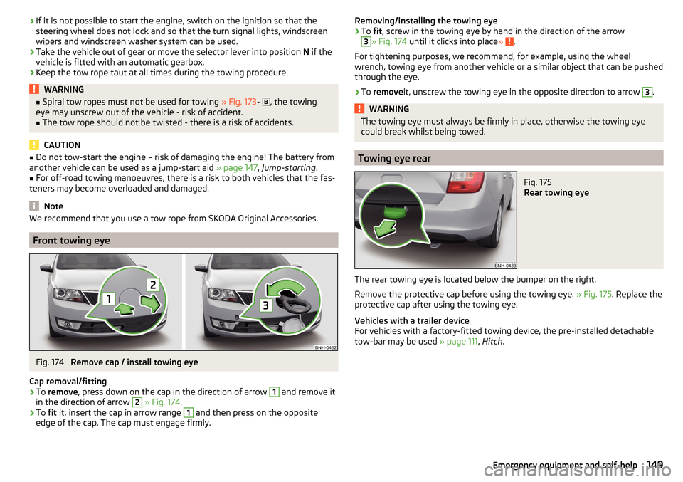
Fig. 174
Remove cap / install towing eye
Cap removal/fitting
›
To remove , press down on the cap in the direction of arrow
1
and remove it
in the direction of arrow
2
» Fig. 174 .
›
To fit it, insert the cap in arrow range
1
and then press on the opposite
edge of the cap. The cap must engage firmly.
Removing/installing the towing eye›To fit, screw in the towing eye by hand in the direction of the arrow3
» Fig. 174 until it clicks into place » .
For tightening purposes, we recommend, for example, using the wheel
wrench, towing eye from another vehicle or a similar object that can be pushed through the eye.
›
To remove it, unscrew the towing eye in the opposite direction to arrow
3
.
WARNINGThe towing eye must always be firmly in place, otherwise the towing eye
could break whilst being towed.
Towing eye rear
Fig. 175
Rear towing eye
The rear towing eye is located below the bumper on the right.
Remove the protective cap before using the towing eye. » Fig. 175. Replace the
protective cap after using the towing eye.
Vehicles with a trailer device
For vehicles with a factory-fitted towing device, the pre-installed detachable
tow-bar may be used » page 111, Hitch .
149Emergency equipment and self-help
Page 171 of 184
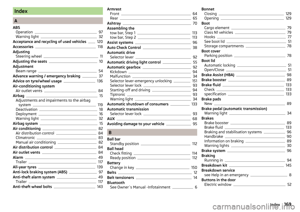
Index
A
ABS Operation
97
Warning light32
Acceptance and recycling of used vehicles
120
Accessories118
Adjusting Steering wheel
11
Adjusting the seats10
Adjustment Beam range
54
Advance warning / emergency braking37
Advice on tyre/wheel usage136
Air-conditioning system Air outlet vents
84
Airbag15
Adjustments and impairments to the airbag system
119
Deactivation18
Deployment16
Warning light32
Airbag system15
Air conditioning82
Air distribution control84
Climatronic83
Manual air conditioning82
Air distribution control84
Air outlet vents84
Alarm49
Trailer117
All-year tyres139
Anti-lock braking system (ABS)97
Anti-theft alarm system49
Trailer117
Anti-theft wheel bolts143
Armrest Front64
Rear65
Ashtray70
Assembling the tow bar, Step 1
113
tow bar, Step 2113
Assist systems96
Auto Check Control38
Automatic drive Selector lever
92
Automatic driving light control55
Automatic gearbox92
Kickdown94
Malfunction34
Selector lever-emergency unlocking151
Selector lever lock93
Starting-off and driving94
Tiptronic93
Warning light34
Automatic shutdown of consumers133
Automatic transmission Selector lever lock
93
AUX68
Avoiding damage to your vehicle95
B
Ball bar Standby position
112
Ball head Check fitting
114
Ready position112
Battery Change in key
150
Belts12
Belt tensioners14
Bluetooth See Owner´s Manual -Infotainment
6
Bonnet Closing129
Opening129
Boot Cargo element
79
Class N1 vehicles79
Hooks77
See boot lid51
Storage compartments78
Boot cover Parking position
78
Boot lid Automatic locking
51
Open/Close51
Brake Assist (HBA)98
Brake booster89
Brake fluid133
Check133
specification133
Brake pads New
89
Brake pedal (automatic transmission) Warning light
34
Brakes Brake booster
89
Brake fluid133
Braking and stabilisation systems96
Handbrake90
Information on braking89
Warning lights30
Brake system96
Braking Running in
94
Breakdown kit145
Breakdown service see Help in an emergency
8
Buttons in the door Electric window
52
169Index