display SKODA ROOMSTER 2006 1.G Owner's Guide
[x] Cancel search | Manufacturer: SKODA, Model Year: 2006, Model line: ROOMSTER, Model: SKODA ROOMSTER 2006 1.GPages: 274, PDF Size: 48.64 MB
Page 36 of 274
Instruments and Indicator/Warning Lights35
Using the systemSafetyDriving TipsGeneral MaintenanceBreakdown assistanceTechnical Data
Selector lever lock* (automatic gearbox)
If the warning light lights up, operate the brake pedal. This is neces-
sary, in order to be able to move the selector lever out of the position P or
N .
Electronic stability programme (ESP)*
The warning light comes on for a few seconds when the ignition is
switched on.
Components of the ESP system also include the Traction Control System
(TCS), Electronic Differential Lock (EDL), and the Antilock Brake System
ABS (ABS).
The warning light comes on when driving when a control cycle is acti-
vated.
The warning light will come on and remains on if the ESP is switched off
or if there is a fault in the system.
The fact that the ESP system operates together with the ABS means that
the ESP warning light will also come on if the ABS system is not operating
properly.
Further information on the ESP ⇒page 177, “Electronic stability
programme (ESP)*”.
Electronic Differential Lock (EDL)*
The EDL is a part of the ESP. A fault in the EDL is indicated by the ESP
warning light
in the instrument cluster. Have the vehicle inspected
immediately by your specialist garage. Further information on the EDL
⇒ page 179.
Antilock brake system (ABS)*
The warning light shows the functionality of the ABS.
The warning light comes on for a few seconds after the ignition has been
switched on or when starting the engine. The warning light goes out after
an automatic check sequence has been completed.
A fault in the ABS
The system is not functioning properly if the ABS warning light
does
not go out within a few seconds after switching on the ignition, does not
light up at all or lights up while driving. The vehicle will only be braked by
the normal brake system. Visit a specialist garage as quickly as possible
and adjust your style of driving in the meantime since you will not know
how great the damage is.
Three additional warning tones will sound if there is a major fault in the
ABS.
Further information about ABS ⇒page 181, “Antilock brake system
(ABS)*”.
A fault in the entire brake system
If the ABS warning light
comes on together with the brake system
warning light (handbrake must be released), there is a fault not only in
the ABS but also in another part of the brake system ⇒.
The following text will be displayed in the information display*: STOP BRAKE FAULT OWNER'S MANUAL!
WARNING
•If the brake system warning light comes on together with the
ABS warning light stop the vehicle immediately and check the
brake fluid level in the reservoir ⇒page 218, “Brake fluid”. If the
fluid level has dropped below the MIN marking, do not drive any
NKO 20 A05.book Page 35 Wednesday, June 21, 2006 1:42 PM
Page 37 of 274
Instruments and Indicator/Warning Lights
36
further - risk of accident! Contact a Škoda dealer to obtain profes-
sional assistance.
•Pay attention to the following instructions ⇒page 210,
“Working in the engine compartment” before checking the brake
fluid level and opening the bonnet.
•If the brake fluid is at the correct level, the ABS control function
has failed. The rear wheels may then block very rapidly when
braking. In certain circumstances, this can result in the rear end of
the car breaking away - risk of skidding! Drive carefully to the
nearest specialist garage and have the fault rectified.
Brake system
The warning light flashes or comes on if the brake fluid level is too low,
if there is a fault in the ABS or if the handbrake is applied.
If the warning light
flashes (handbrake is not applied), stop and check
the brake fluid level ⇒.
The following text will be displayed in the information display*: STOP BRAKE FLUID OWNER'S MANUAL
If there is a fault in the ABS which also influences the function of the
normal brake system (e.g. distribution of brake pressure), the ABS
warning light
comes on together with the brake system warning light . Be aware that not only the ABS but also another part of th brake
system is defective ⇒.
3 peeps sound as an additional warning signal.
One should get used to high pedal forces, long braking distances and long
free play of the brake pedal when driving to the next specialist garage. The following text will be displayed in the information display*:
STOP BRAKE FAULT OWNER'S MANUAL!
For further information on the brake system ⇒page 180, “Brakes”.
Handbrake applied
The warning light
also comes on if the handbrake is applied. An audible
warning is also given if you drive the vehicle for at least 3 seconds at a
speed of more than 6 km/h.
The following text will be displayed in the information display*:
HANDBRAKE ON
WARNING
•Pay attention to the following instructions ⇒page 210,
“Working in the engine compartment” before checking the brake
fluid level and opening the bonnet.
•If the brake system warning light does not go out a few
seconds after switching on the igni tion or comes on when driving,
stop immediately and check the brake fluid in the reservoir
⇒ page 218, “Brake fluid”. If the fluid level has dropped below the
MIN marking, do not drive any furthe r - risk of accident! Contact a
Škoda dealer to obtain professional assistance.
Airbag system
Monitoring the airbag system
The warning light
comes on for a few seconds when the ignition is
switched on.
WARNING (continued)
NKO 20 A05.book Page 36 Wednesday, June 21, 2006 1:42 PM
Page 38 of 274
Instruments and Indicator/Warning Lights37
Using the systemSafetyDriving TipsGeneral MaintenanceBreakdown assistanceTechnical Data
There is a fault in the system if the warning light does not go out or comes
on or flashes while driving
⇒. This also applies if the warning light
does not come on after the ignition is switched on.
The following text will be displayed in the information display*:
AIRBAG FAULT
The functionality of the airbag system is also monitored electronically,
when one airbag has been switched off.
The passenger front airbag and also possibly the passenger side
airbag which have been switched off using the vehicle system tester:
•The warning light lights up for 3 seconds after switching on the igni-
tion and then flashes for 12 seconds afterwards in 2 second intervals.
The passenger front airbag and also possibly the passenger side
airbag which have been switched off using the switch (for switching
off airbags)* in the end face of the dash panel on the front passenger
side:
•The warning light comes on for 3 seconds after the ignition has
been switched on.
•Switching off airbags is indicated in the middle of the dash panel by the
lighting up of the indicator light (airbag switched off)
⇒ page 164.
WARNING
Have the airbag system checked immediately by a specialist
garage if a fault exists. Otherwise, there is a risk of the airbag not
being activated in the event of an accident.
Note
Further information about switching off airbags ⇒page 163, “Deactivating
an airbag”.
Diesel particle filter* (diesel engine)
In the diesel particle filter the resulting soot particles are
collected and burnt during the combustion of diesel fuel.
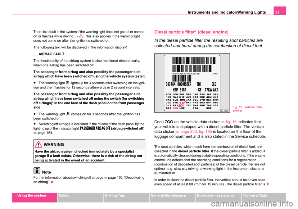
Code 7GG on the vehicle data sticker ⇒fig. 16 indicates that
your vehicle is equipped with a diesel particle filter. The vehicle
data sticker ⇒page 263, fig. 195 is located on the floor of the
luggage compartment and is also stated in the Service schedule.
The soot particles, which result from the combustion of diesel fuel, are
collected in the diesel particle filter . If the diesel particle filter is added, it
is automatically cleaned during suitable operating conditions. If the engine
control unit detects that the operating conditions for a regeneration
(combustion of deposited soot particles) of the diesel particle fiter are not
optimal, e.g. slow city driving, a warning light in the instrument cluster is
illuminated
.
In order to clean the diesel particle filter, the vehicle should be driven at an
even speed of at least 60 km/h for 15 minutes. The diesel particle filter is
Fig. 16 Vehicle data
sticker
NKO 20 A05.book Page 37 Wednesday, June 21, 2006 1:42 PM
Page 39 of 274
Instruments and Indicator/Warning Lights
38
most effectively cleaned if the vehicle is driven in the 4th or 5th gear within
the range of 2 000 to 3 000 rpm.
If these conditions are not met, the warning light
does not go out and
after 10 minutes the warning light begins to flash. ENGINE FAULT
WORKSHOP! is shown in the information display. Afterwards the engine
control unit shifts the engine into the emergency mode, which only has a
reduced power output. After switching the ignition off and on again the
warning light
comes on.
Have the vehicle inspected without delay by your specialist garage.
WARNING
•Please pay attention to the traffic regulations and speed limits.
•The diesel particle filter achieves very high temperatures.
Therefore do not park at points where the hot filter comes into
direct contact with dry grass or other combustible materials - risk
of fire!
•Use neither protective paint for chassis nor anti-corrosion
agent, in order to treat the exhaust system, the heat shields or the
diesel particle filter. The high temperatures can cause the coating
to ignite!
Note
•It is prohibited to use biofuel (RME) and diesel fuel mixture for diesel
vehicles which are fitted with diesel particle filter.
•When using diesel fuel with high sulphur content the life of the diesel
particle filter is clearly reduced. A specialist garage will be able to tell you
which countries offer only diesel fuel with high sulphur content.
Seat belt warning light*
The warning light comes on after the ignition is switched on as a
reminder to fasten the seat belt.
If the seat belts are not fastened when the speed of the car increases to
more than 25km/h, the warning light flashes and an acoustic warning
signal sounds for approx. 90 seconds.
The following text will be displayed in the information display*:
FASTEN SEAT BELT
For further information on the seat belts ⇒page 147, “Why seat belts?”.
NKO 20 A05.book Page 38 Wednesday, June 21, 2006 1:42 PM
Page 105 of 274
Heating and air conditioning system
104
Climatronic (automatic air conditioning)*
Description
The Climatronic system is a combination of an automatic
heating, fresh air and cooling system which provides
optimal comfort for the occupants of the car.
The Climatronic maintains a constant temperature fully automatically,
once it has been set. This is achieved by automatically varying the
temperature of the outflowing air, the blower stages and the air distribu-
tion. The system also takes into account sunlight which eliminates the
need to alter the settings manually. The automatic mode ⇒ page 106
ensures maximum wellbeing of the occupants at all times of the year.
Description of Climatronic system
The cooling operates only if the following conditions are met:
•engine running,
•outside temperature above +2 °C,
•the button is not pressed.
If the cooling system is switched on, the temperature and air humidity
drops in the vehicle. The wellbeing of the occupants of the car is enhanced
as a result of this particularly at high outside temperatures and a high air
humidity. The system prevents the windows misting up during the cold
season of the year.
The heating effect is dependent upon the coolant temperature, thus full
heat output only occurs when the engine has reached its operating
temperature.
It is possible to briefly activate recirculated air mode in order to enhance
the cooling effect ⇒. The air inlet in front of the windscreen must be free of ice, snow or leaves
in order to ensure that the heating and cooling systems operate properly.
The AC compressor is switched off at a high coolant temperature in order
to provide cooling at a high load of the engine.
After switching on the cooling
Condensation from the evaporator of the
air conditioning may drip down and form a puddle below the vehicle. This
is quite normal and not an indication of a leak!
Recommended setting for all periods of the year:
•Set the temperature to 22 °C.
•Press the button ⇒page 105, fig. 96 .
•Move the air outlet vents 3 and 4 so that the air flow is directed slightly
upwards ⇒page 108, fig. 97 .
Switching over between degrees Celsius and degrees Fahrenheit
Press and hold the buttons and ⇒page 105, fig. 96 . The
information in the desired temperature measuring unit appears in the
display.
WARNING
•For your own safety and that of other road users, ensure that all
the windows are free of ice, snow and misting. Please familiarize
yourself about how to correctly operate the heating and ventilation
systems, how to demist and defrost the windows, as well as with
the cooling mode.
•You should not leave recirculated air mode on over a longer
period of time, as “stale” air may result in fatigue in the driver and
occupants, divert your attention and also cause the windows to
mist up. The risk of having an accident increases. Switch recircu-
lated air mode off as soon as the windows begin misting up.
ECON
AUTO
ECONAUTO
NKO 20 A05.book Page 104 Wednesday, June 21, 2006 1:42 PM
Page 106 of 274
Heating and air conditioning system 105
Using the systemSafetyDriving TipsGeneral MaintenanceBreakdown assistanceTechnical Data
Note
•If the cooling system has not been switched on for a lengthy period,
odours may be produced at the evaporator because of deposits. Switch
the cooling system on at least once a month for approximately 5 minutes
at the highest blower stage - also during the cold season of the year - in
order to remove such odours. Also open a window for a short time.
•We recommend that you do not smoke in the vehicle when the recir-
culating air mode is operating since the smoke which is drawn at the evap-
orator from the interior of the vehicle forms deposits in the evaporator of
the air conditioning system. This produces a permanent odour when the
air conditioning system is operating which can only be eliminated through
considerable effort and expense (replacement of compressor).
•The used air streams out through the air removal openings in the
luggage compartment.
•Using the cooling economically ⇒page 103.
•Operational problems ⇒page 103.
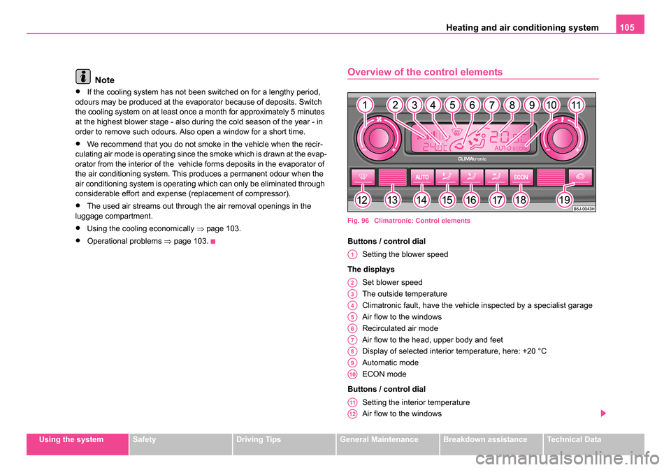
Overview of the control elements
Fig. 96 Climatronic: Control elements
Buttons / control dial
Setting the blower speed
The displays Set blower speed
The outside temperature
Climatronic fault, have the vehicle inspected by a specialist garage
Air flow to the windows
Recirculated air mode
Air flow to the head, upper body and feet
Display of selected interior temperature, here: +20 °C
Automatic mode
ECON mode
Buttons / control dial Setting the interior temperature
Air flow to the windows
A1
A2
A3
A4
A5
A6
A7
A8
A9
A10
A11
A12
NKO 20 A05.book Page 105 Wednesday, June 21, 2006 1:42 PM
Page 107 of 274
Heating and air conditioning system
106
Automatic mode
Air flow in the footwell
Air flow to the upper body
Air flow to head
Button for switching off cooling system
Recirculated air mode
Note
The interior temperature sensor is located in the bottom part of the
device. Do not glue or cover over the sensor, otherwise it could have an
unfavourable effect on the Climatronic.
Automatic mode
The automatic mode is used in order to maintain a
constant temperature and to keep the windows in the inte-
rior of the car dry.
Switching automatic mode on
– Set a temperature between +18 °C and +29 °C.
– Move the air outlet vents 3 and 4 ⇒ page 108, fig. 97 so that
the air flow is directed slightly upwards.
– Press the button , AUTO appears in the display.
The automatic mode is switched off by pressing the button for the air distri-
bution or increasing or decreasing the blower speed. The temperature is
nevertheless regulated.
ECON mode
The cooling system is switched off in the ECON mode -
heating and ventilation are regulated automatically.
Switching ECON mode on
– Press the button , ECON appears in the display.
– Set a temperature between +18 °C and +29 °C.
Recirculated air mode in ECON mode
– Press the button , AUTO appears in the display.
– Press the button , ECON appears in the display.
ECON mode operates only within the control temperature range from +18
°C up to +29 °C.
The ECON mode is switched off when pressing button or .
Please note that, in the ECON mode, the interior temperature cannot be
lower than the outside temperature. The interior is not cooled and the air
is not dehumidified.
Please refer to the information regarding recirculated air mode
⇒page 107.
Defrosting windscreen
Defrosting windscr een - switching on
– Press the button ⇒page 105, fig. 96 .
A14
A15
A15
A17
A18
A19
A13
AUTO
ECON
ECON
NKO 20 A05.book Page 106 Wednesday, June 21, 2006 1:42 PM
Page 108 of 274
Heating and air conditioning system 107
Using the systemSafetyDriving TipsGeneral MaintenanceBreakdown assistanceTechnical Data
Defrosting windscreen - switching off
– Once again press the button or the button .
The temperature control is controlled automatically. More air flows out of
the air outlet vents 1 and 2.
Recirculated air mode
In recirculated air mode air is sucked out of the interior of
the vehicle and then fed back into the interior.
Recirculated air mode prevents polluted air outside the vehicle
from getting into the vehicle, for example when driving through a
tunnel or when standing in a traffic jam.
Switching recirculated air mode on
– Press button , the symbol
appears on the display.
Switching recirculated air mode off
– Once again press the button or the button , the symbol or the logo is no longer shown on the display.
WARNING
You should not leave recirculated air mode on over a longer period
of time, as “stale” air may result in fatigue in the driver and occu-
pants, divert your attention and also cause the windows to mist up.
The risk of having an accident increases. Switch recirculated air
mode off as soon as the windows begin misting up.
Note
If the windscreen mists up, press the button . After the windscreen has
been demisted, press the button .
Setting temperature
– You can set the desired interior temperature after switching on the ignition with the control dial .
You can set the interior temperature between +18°C and +29°C. The inte-
rior temperature is regulated automatically within this range. If you select
a temperature of less than +18 °C, “LO” is shown on the display. If you
select a temperature above +29 °C, “HI” is shown on the display. In both
limit positions the Climatronic operates at maximum cooling or heating
capacity, respectively. The temperature is not controlled in this case.
Lengthy and uneven distribution of the air flow out of the vents (in partic-
ular at the leg area) and large differences in temperature, for example
when getting out of the vehicle, can result in chills in sensitive persons.
Controlling blower
There are a total of seven blower stages available.
The Climatronic system controls the blower stages automatically
in line with the interior temperature. You can also, however, adapt
the blower stages manually to suit your particular needs.
– Turn the control dial ⇒page 105, fig. 96 to the left (reduce
blower speed) or right (increase blower speed).
AUTO
AUTO
AUTO
A11
A1
NKO 20 A05.book Page 107 Wednesday, June 21, 2006 1:42 PM
Page 109 of 274
Heating and air conditioning system
108
Switch off the blowers, the Climatronic is switched off and in the display
shows OFF.
The set blower speed is displayed next to the control dial when the
respective number of warning lights come on.
WARNING
•“Stale air” may result in fatigue in the driver and occupants,
reduce attention levels and also cause the windows to mist up. The
risk of having an accident increases.
•Do not switch the Climatronic system off for longer than neces-
sary.
•Switch the Climatronic system on as soon as the windows mist
up.
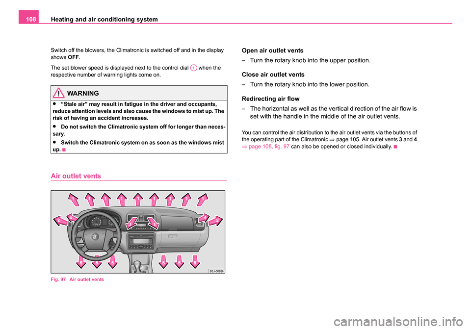
Air outlet vents
Fig. 97 Air outlet vents
Open air outlet vents
– Turn the rotary knob into the upper position.
Close air outlet vents
– Turn the rotary knob into the lower position.
Redirecting air flow
– The horizontal as well as the vertical direction of the air flow is set with the handle in the middle of the air outlet vents.
You can control the air distribution to the air outlet vents via the buttons of
the operating part of the Climatronic ⇒page 105. Air outlet vents 3 and 4
⇒ page 108, fig. 97 can also be opened or closed individually.
A1
NKO 20 A05.book Page 108 Wednesday, June 21, 2006 1:42 PM
Page 115 of 274
Starting-off and Driving
114
•Depress the clutch pedal fully when changing gears, in order to avoid
unnecessary wear and damage.
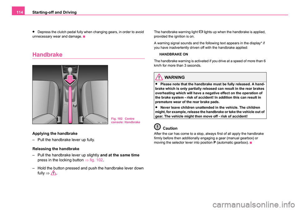
Handbrake
Applying the handbrake
– Pull the handbrake lever up fully.
Releasing the handbrake
– Pull the handbrake lever up slightly and at the same time
press in the locking button ⇒fig. 102 .
– Hold the button pressed and push the handbrake lever down fully ⇒ .
The handbrake warning light lights up when the handbrake is applied,
provided the ignition is on.
A warning signal sounds and the following text appears in the display* if
you have inadvertently driven off with the handbrake applied:
HANDBRAKE ON
The handbrake warning is activated if you drive at a speed of more than 6
km/h for more than 3 seconds.
WARNING
•Please note that the handbrake must be fully released. A hand-
brake which is only partially released can result in the rear brakes
overheating which will have a negative effect on the operation of
the brake system - risk of accident! In addition this can result in
premature wear of the rear brake pads.
•Never leave children unattended in the vehicle. The children
might, for example, release the handbrake or take the vehicle out of
gear. The vehicle might then move off - risk of accident!
Caution
After the car has come to a stop, always first of all apply the handbrake
firmly before then additionally engaging a gear (manual gearbox) or
moving the selector lever into position P (automatic gearbox).
Fig. 102 Centre
console: Handbrake
NKO 20 A05.book Page 114 Wednesday, June 21, 2006 1:42 PM