battery SKODA ROOMSTER 2006 1.G Owner's Manual
[x] Cancel search | Manufacturer: SKODA, Model Year: 2006, Model line: ROOMSTER, Model: SKODA ROOMSTER 2006 1.GPages: 274, PDF Size: 48.64 MB
Page 7 of 274
Contents
6
Airbag system. . . . . . . . . . . . . . . . . . . . . . . . .
Description of the airbag system . . . . . . . . . .
Front airbags . . . . . . . . . . . . . . . . . . . . . . . . .
Side airbags* . . . . . . . . . . . . . . . . . . . . . . . . .
Head airbags* . . . . . . . . . . . . . . . . . . . . . . . .
Deactivating an airbag . . . . . . . . . . . . . . . . . .
Transporting children safely. . . . . . . . . . . . .
What you should know about transporting
children! . . . . . . . . . . . . . . . . . . . . . . . . . . . . .
Child seat . . . . . . . . . . . . . . . . . . . . . . . . . . . .
Attaching a child seat using the “ISOFIX”
system* . . . . . . . . . . . . . . . . . . . . . . . . . . . . .
Attaching child seat using the “Top Tether”
system . . . . . . . . . . . . . . . . . . . . . . . . . . . . . .
Driving Tips . . . . . . . . . . . . . . . . . . . . . .
Intelligent Technology . . . . . . . . . . . . . . . . . .
Electronic stability programme (ESP)* . . . . . .
Brakes . . . . . . . . . . . . . . . . . . . . . . . . . . . . . .
Brake booster . . . . . . . . . . . . . . . . . . . . . . . .
Antilock brake system (ABS)* . . . . . . . . . . . .
Brake Assist* . . . . . . . . . . . . . . . . . . . . . . . . .
Power steering* . . . . . . . . . . . . . . . . . . . . . . .
Tyre inflation pressure-control system* . . . . .
Driving and the Environment. . . . . . . . . . . .
The first 1 500 kilometres and then afterwards
Catalytic converter . . . . . . . . . . . . . . . . . . . . .
Driving in an economical and environmentally
conscious manner . . . . . . . . . . . . . . . . . . . . .
Environmental compatibility . . . . . . . . . . . . . .
Motoring abroad . . . . . . . . . . . . . . . . . . . . . . .
Avoiding damage to your vehicle . . . . . . . . . .
Towing a trailer . . . . . . . . . . . . . . . . . . . . . . . .
Towing a trailer . . . . . . . . . . . . . . . . . . . . . . . .
General Maintenance. . . . . . . . . .
Taking care of your vehicle and cleaning the
vehicle . . . . . . . . . . . . . . . . . . . . . . . . . . . . . . .
General . . . . . . . . . . . . . . . . . . . . . . . . . . . . .
Care of the exterior of vehicle . . . . . . . . . . . .
Care of the interior of vehicle . . . . . . . . . . . . .
Fuel. . . . . . . . . . . . . . . . . . . . . . . . . . . . . . . . . .
Petrol . . . . . . . . . . . . . . . . . . . . . . . . . . . . . . .
Diesel . . . . . . . . . . . . . . . . . . . . . . . . . . . . . .
Refuelling . . . . . . . . . . . . . . . . . . . . . . . . . . .
Inspecting and Replenishing. . . . . . . . . . . .
Engine compartment . . . . . . . . . . . . . . . . . . . . . . . . . . . . . . . . . . . . . . . . . . . . . . . . . . . . . .
Cooling system . . . . . . . . . . . . . . . . . . . . . . .
Brake fluid . . . . . . . . . . . . . . . . . . . . . . . . . . .
Battery . . . . . . . . . . . . . . . . . . . . . . . . . . . . . .
Windshield washer system . . . . . . . . . . . . . .
Wheels and Tyres . . . . . . . . . . . . . . . . . . . . .
Wheels . . . . . . . . . . . . . . . . . . . . . . . . . . . . .
Accessories, changes and replacement of
parts . . . . . . . . . . . . . . . . . . . . . . . . . . . . . . . . .
Accessories and replacement parts . . . . . . .
Technical changes . . . . . . . . . . . . . . . . . . . . .
Breakdown assistance . . . . . . . .
Breakdown assistance . . . . . . . . . . . . . . . . .
First-aid box* and Warning triangle* . . . . . . .
Fire extinguisher* . . . . . . . . . . . . . . . . . . . . . .
Vehicle tool kit . . . . . . . . . . . . . . . . . . . . . . . .
Tyre repair kit* . . . . . . . . . . . . . . . . . . . . . . . .
Spare wheel* . . . . . . . . . . . . . . . . . . . . . . . . .
Changing a wheel . . . . . . . . . . . . . . . . . . . . .
Jump-starting . . . . . . . . . . . . . . . . . . . . . . . . .
Tow-starting and towing vehicle . . . . . . . . . . .
Fuses and light bulbs . . . . . . . . . . . . . . . . . .
Electric fuses . . . . . . . . . . . . . . . . . . . . . . . . .
Bulbs . . . . . . . . . . . . . . . . . . . . . . . . . . . . . . .
Te c h n i c a l D a ta . . . . . . . . . . . . . . . . . .
General . . . . . . . . . . . . . . . . . . . . . . . . . . . . . .
Identification data . . . . . . . . . . . . . . . . . . . . .
Index . . . . . . . . . . . . . . . . . . . . . . . . . . . . . .
154
154
156
159
161
163
166
166
170
174
175
177
177
177
180
181
181
182
183
183
185
185
186
187
191
192
192
193
193 197
197
197
197
203
205
205
205
207
209
209
212
215
218
220
224
225
225
232
232
232
235
235
235
235
236
236
237
237
243
245249
249
254
263
263
263
265
NKO 20 A05.book Page 6 Wednesday, June 21, 2006 1:42 PM
Page 18 of 274
Instruments and Indicator/Warning Lights17
Using the systemSafetyDriving TipsGeneral MaintenanceBreakdown assistanceTechnical Data
•affix the sticker with the entry of the following service interval to the
side of the dash panel on the driver's side.
The Service Interval Display can also be reset with the reset button as
follows:
•Switch off the ignition, press the reset button of the trip counter for
distance driven and hold it down.
•Switch the ignition on and release the reset button. Now turn the reset
button to the right. The service interval display is reset.
Caution
We recommend that you do not reset the Service Interval Display yourself
otherwise this can result in the service interval display being incorrectly
set, which may also result in problems with operation of your vehicle.
Note
•Never reset the display between service intervals otherwise this may
result in incorrect readouts.
•information is retained in the Service Interval Display also after the
battery of the vehicle is disconnected.
•it is necessary to re-code the Service Interval Display if a new instru-
ment cluster is installed during repair work. This work is carried out by a
specialist garage.
•The data displayed is the same after resetting the display with flexible
service intervals (QG1) using the reset button as that for a vehicle with
fixed service intervals (QG2). We therefore recommend having the
Service Interval Display reset only by a Škoda Service Partner who is
familiar with the procedure for resetting the display with a vehicle system
tester.
•Please refer to the brochure Service schedule for extensive informa-
tion about the service intervals.
Digital clock
A reset button is installed on the left below beside the speedom-
eter for adjusting the clock ⇒page 13, fig. 2 .
Set hours
– Turn the reset button to the left.
Setting minutes
– Turn the reset button to the right.
WARNING
The clock should not be adjusted while driving for safety reasons
but only when the vehicle is stationary.
Multi-functional indicator (onboard
computer)*
Introduction
The multi-functional indicator appears in the display ⇒page 18, fig. 5 or
in the information display ⇒page 22, fig. 8 depending on the equipment
fitted to your vehicle.
The multi-functional indicator offers you a range of useful information
A6
NKO 20 A05.book Page 17 Wednesday, June 21, 2006 1:42 PM
Page 19 of 274
Instruments and Indicator/Warning Lights
18
Note
In certain national versions the displays appear in the Imperial system of
measures.
Memory
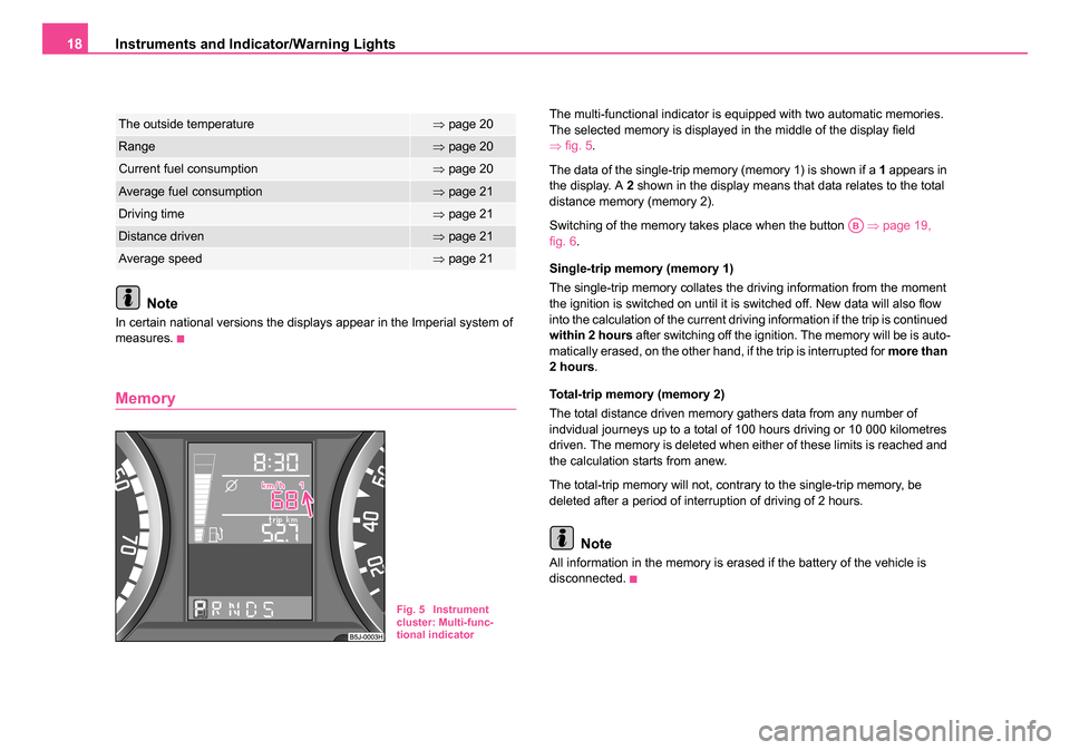
The multi-functional indicator is equipped with two automatic memories.
The selected memory is displayed in the middle of the display field
⇒fig. 5 .
The data of the single-trip memory (memory 1) is shown if a 1 appears in
the display. A 2 shown in the display means that data relates to the total
distance memory (memory 2).
Switching of the memory takes place when the button ⇒page 19,
fig. 6 .
Single-trip memory (memory 1)
The single-trip memory collates the driving information from the moment
the ignition is switched on until it is switched off. New data will also flow
into the calculation of the current driving information if the trip is continued
within 2 hours after switching off the ignition. The memory will be is auto-
matically erased, on the other hand, if the trip is interrupted for more than
2 hours .
Total-trip memory (memory 2)
The total distance driven memory gathers data from any number of
indvidual journeys up to a total of 100 hours driving or 10 000 kilometres
driven. The memory is deleted when either of these limits is reached and
the calculation starts from anew.
The total-trip memory will not, contrary to the single-trip memory, be
deleted after a period of interruption of driving of 2 hours.
Note
All information in the memory is erased if the battery of the vehicle is
disconnected.
The outside temperature⇒ page 20
Range⇒page 20
Current fuel consumption⇒page 20
Average fuel consumption⇒page 21
Driving time⇒page 21
Distance driven⇒page 21
Average speed⇒page 21
Fig. 5 Instrument
cluster: Multi-func-
tional indicator
AB
NKO 20 A05.book Page 18 Wednesday, June 21, 2006 1:42 PM
Page 21 of 274
Instruments and Indicator/Warning Lights
20
Outside temperature
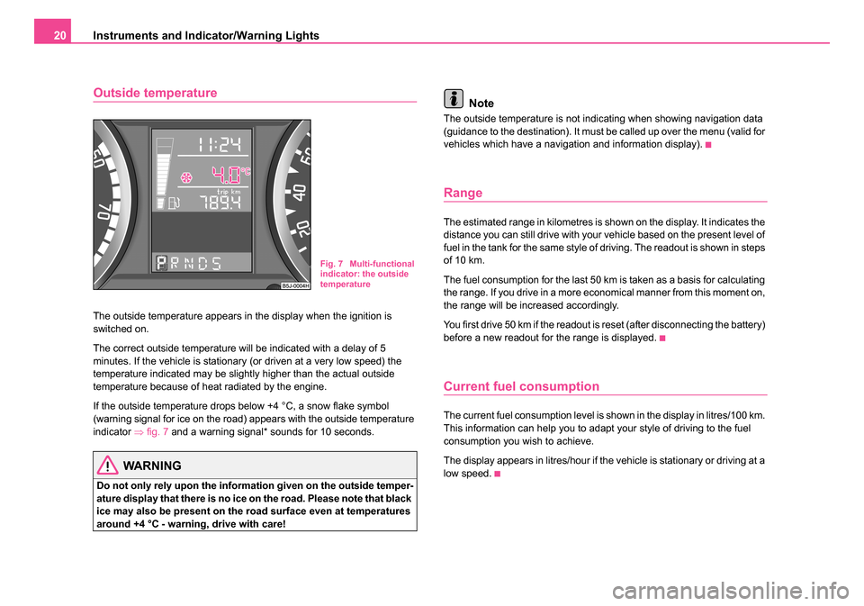
The outside temperature appears in the display when the ignition is
switched on.
The correct outside temperature will be indicated with a delay of 5
minutes. If the vehicle is stationary (or driven at a very low speed) the
temperature indicated may be slightly higher than the actual outside
temperature because of heat radiated by the engine.
If the outside temperature drops below +4 °C, a snow flake symbol
(warning signal for ice on the road) appears with the outside temperature
indicator ⇒fig. 7 and a warning signal* sounds for 10 seconds.
WARNING
Do not only rely upon the information given on the outside temper-
ature display that there is no ice on the road. Please note that black
ice may also be present on the road surface even at temperatures
around +4 °C - warning, drive with care!
Note
The outside temperature is not indicating when showing navigation data
(guidance to the destination). It must be called up over the menu (valid for
vehicles which have a navigation and information display).
Range
The estimated range in kilometres is shown on the display. It indicates the
distance you can still drive with your vehicle based on the present level of
fuel in the tank for the same style of driving. The readout is shown in steps
of 10 km.
The fuel consumption for the last 50 km is taken as a basis for calculating
the range. If you drive in a more economical manner from this moment on,
the range will be increased accordingly.
You first drive 50 km if the readout is reset (after disconnecting the battery)
before a new readout for the range is displayed.
Current fuel consumption
The current fuel consumption level is shown in the display in litres/100 km.
This information can help you to adapt your style of driving to the fuel
consumption you wish to achieve.
The display appears in litres/hour if the vehicle is stationary or driving at a
low speed.
Fig. 7 Multi-functional
indicator: the outside
temperature
NKO 20 A05.book Page 20 Wednesday, June 21, 2006 1:42 PM
Page 30 of 274
Instruments and Indicator/Warning Lights29
Using the systemSafetyDriving TipsGeneral MaintenanceBreakdown assistanceTechnical Data
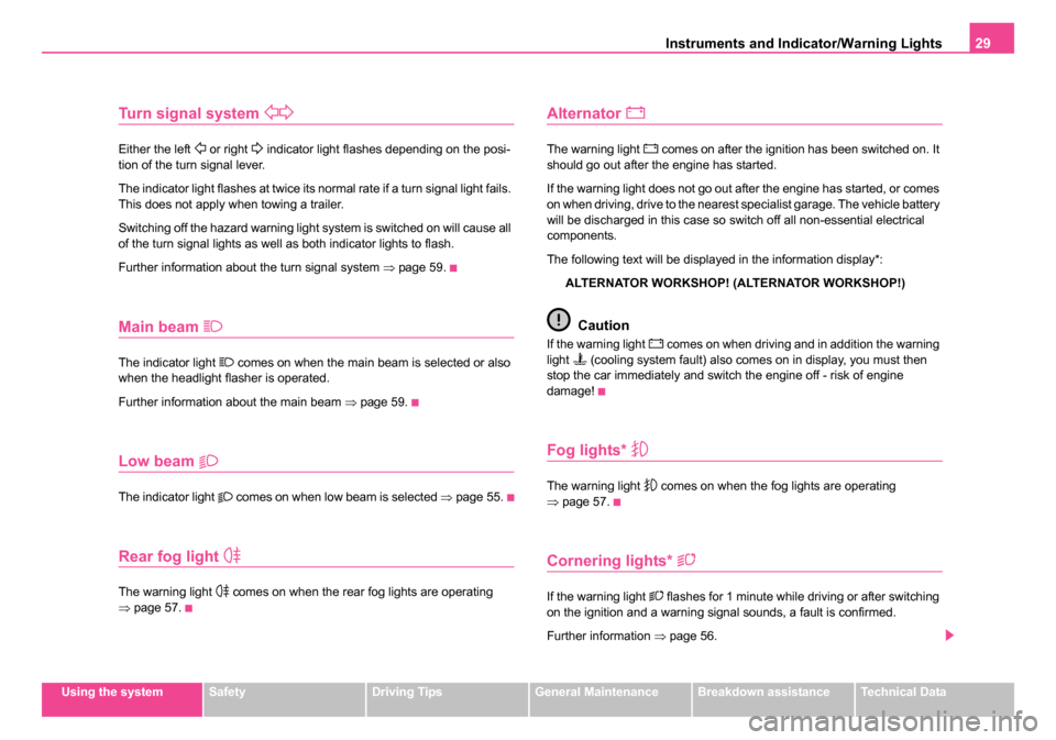
Turn signal system
Either the left or right indicator light flashes depending on the posi-
tion of the turn signal lever.
The indicator light flashes at twice its normal rate if a turn signal light fails.
This does not apply when towing a trailer.
Switching off the hazard warning light system is switched on will cause all
of the turn signal lights as well as both indicator lights to flash.
Further information about the turn signal system ⇒page 59.
Main beam
The indicator light comes on when the main beam is selected or also
when the headlight flasher is operated.
Further information about the main beam ⇒page 59.
Low beam
The indicator light comes on when low beam is selected ⇒page 55.
Rear fog light
The warning light comes on when the rear fog lights are operating
⇒ page 57.
Alternator
The warning light comes on after the ignition has been switched on. It
should go out after the engine has started.
If the warning light does not go out after the engine has started, or comes
on when driving, drive to the nearest specialist garage. The vehicle battery
will be discharged in this case so switch off all non-essential electrical
components.
The following text will be displayed in the information display*:
ALTERNATOR WORKSHOP! (ALTERNATOR WORKSHOP!)
Caution
If the warning light comes on when driving and in addition the warning
light (cooling system fault) also comes on in display, you must then
stop the car immediately and switch the engine off - risk of engine
damage!
Fog lights*
The warning light comes on when the fog lights are operating
⇒ page 57.
Cornering lights*
If the warning light flashes for 1 minute while driving or after switching
on the ignition and a warning signal sounds, a fault is confirmed.
Further information ⇒page 56.
NKO 20 A05.book Page 29 Wednesday, June 21, 2006 1:42 PM
Page 31 of 274
Instruments and Indicator/Warning Lights
30
WARNING
If there is a fault in the cornering lights, the headlights are automat-
ically lowered to the emergency position. Thus the illuminated
length of the road is shortened. Drive carefully and have the car
inspected immediately by a specialist garage.
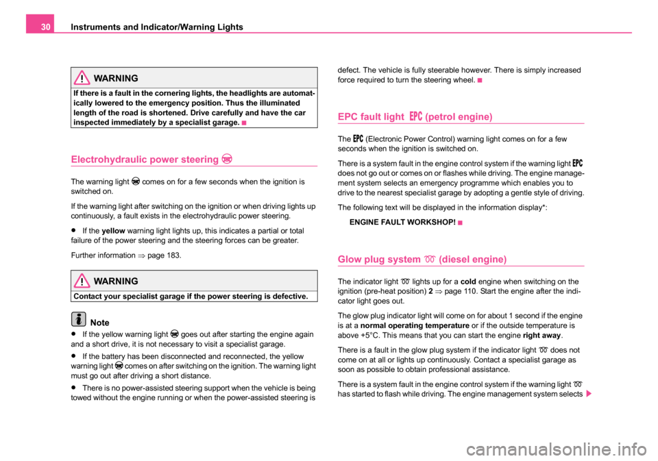
Electrohydraulic power steering
The warning light comes on for a few seconds when the ignition is
switched on.
If the warning light after switching on the ignition or when driving lights up
continuously, a fault exists in the electrohydraulic power steering.
•If the yellow warning light lights up, this indicates a partial or total
failure of the power steering and the steering forces can be greater.
Further information ⇒page 183.
WARNING
Contact your specialist garage if the power steering is defective.
Note
•If the yellow warning light goes out after starting the engine again
and a short drive, it is not necessary to visit a specialist garage.
•If the battery has been disconnected and reconnected, the yellow
warning light comes on after switching on the ignition. The warning light
must go out after driving a short distance.
•There is no power-assisted steering support when the vehicle is being
towed without the engine running or when the power-assisted steering is defect. The vehicle is fully steerable however. There is simply increased
force required to turn the steering wheel.
EPC fault light (petrol engine)
The (Electronic Power Control) warning light comes on for a few
seconds when the ignition is switched on.
There is a system fault in the engine control system if the warning light
does not go out or comes on or flashes while driving. The engine manage-
ment system selects an emergency programme which enables you to
drive to the nearest specialist garage by adopting a gentle style of driving.
The following text will be displayed in the information display*:
ENGINE FAULT WORKSHOP!
Glow plug system (diesel engine)
The indicator light lights up for a cold engine when switching on the
ignition (pre-heat position) 2 ⇒ page 110. Start the engine after the indi-
cator light goes out.
The glow plug indicator light will come on for about 1 second if the engine
is at a normal operating temperature or if the outside temperature is
above +5°C. This means that you can start the engine right away.
There is a fault in the glow plug system if the indicator light
does not
come on at all or lights up continuously. Contact a specialist garage as
soon as possible to obtain professional assistance.
There is a system fault in the engine control system if the warning light
has started to flash while driving. The engine management system selects
NKO 20 A05.book Page 30 Wednesday, June 21, 2006 1:42 PM
Page 32 of 274
Instruments and Indicator/Warning Lights31
Using the systemSafetyDriving TipsGeneral MaintenanceBreakdown assistanceTechnical Data
an emergency programme which enables you to drive to the nearest
specialist garage by adopting a gentle style of driving.
The following text will be displayed in the information display*:
ENGINE FAULT WORKSHOP!
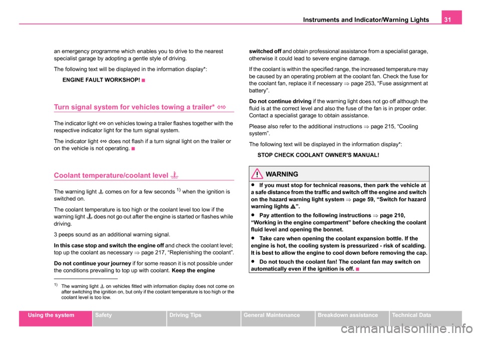
Turn signal system for vehicles towing a trailer*
The indicator light on vehicles towing a trailer flashes together with the
respective indicator light for the turn signal system.
The indicator light
does not flash if a turn signal light on the trailer or
on the vehicle is not operating.
Coolant temperature/coolant level
The warning light comes on for a few seconds 1) when the ignition is
switched on.
The coolant temperature is too high or the coolant level too low if the
warning light
does not go out after the engine is started or flashes while
driving.
3 peeps sound as an additional warning signal.
In this case stop and switch the engine off and check the coolant level;
top up the coolant as necessary ⇒page 217, “Replenishing the coolant”.
Do not continue your journey if for some reason it is not possible under
the conditions prevailing to top up with coolant. Keep the engine switched off
and obtain professional assistance from a specialist garage,
otherwise it could lead to severe engine damage.
If the coolant is within the specified range, the increased temperature may
be caused by an operating problem at the coolant fan. Check the fuse for
the coolant fan, replace it if necessary ⇒page 253, “Fuse assignment at
battery”.
Do not continue driving if the warning light does not go off although the
fluid is at the correct level and also the fuse of the fan is in proper order.
Contact a specialist garage to obtain assistance.
Please also refer to the additional instructions ⇒page 215, “Cooling
system”.
The following text will be displayed in the information display*:
STOP CHECK COOLANT OWNER'S MANUAL!
WARNING
•If you must stop for technical reasons, then park the vehicle at
a safe distance from the traffic and switch off the engine and switch
on the hazard warning light system ⇒page 59, “Switch for hazard
warning lights ”.
•Pay attention to the following instructions ⇒page 210,
“Working in the engine compartment” before checking the coolant
fluid level and opening the bonnet.
•Take care when opening the coolant expansion bottle. If the
engine is hot, the cooling system is pressurized - risk of scalding.
It is best to allow the engine to cool down before removing the cap.
•Do not touch the coolant fan! The coolant fan may switch on
automatically even if the ignition is off.
1)The warning light on vehicles fitted with information display does not come on
after switching the ignition on, but only if the coolant temperature is to\
o high or the
coolant level is too low.
NKO 20 A05.book Page 31 Wednesday, June 21, 2006 1:42 PM
Page 35 of 274

Instruments and Indicator/Warning Lights
34
The following text will be displayed in the information display*:
EXHAUST WORKSHOP!
Traction control system (TCS)
The warning light comes on for a few seconds when the ignition is
switched on.
The warning light comes on when driving when a control cycle is acti-
vated.
The warning light will come on and remains on if the TCS is switched off
or if there is a fault in the system.
The fact that the TCS system operates together with the ABS means that
the TCS warning light will also come on if the ABS system is not operating
properly.
If the warning light
comes on immediately after starting the engine, the
TCS system can be switched off for technical reasons. In this case, the
TCS system can be switched on again by switching the ignition on and off.
If the warning light goes out, the TCS system is fully functional again.
Further information about the TCS ⇒page 178.
Note
If the battery has been disconnected and reconnected, the warning light comes on after switching on the ignition. The warning light must go out
after driving a short distance.
Tyre inflation pressure*
The warning light lights up, if there is a substantial drop in inflation
pressure in one of the tyres. Reduce the speed and check or correct as
soon as possible the inflation pressure in the tyres ⇒page 226.
A peep sounds as an additional warning signal.
If the warning light flashes, there is a system fault. Visit the nearest
specialist garage and have the fault rectified.
Further information about tyre pressure-control system ⇒page 183.
WARNING
•When the warning light lights up, immediately reduce the
speed and avoid sudden steering and brake manoeuvres. Please
stop the vehicle without delay at the nearest possible stop and
inspect the tyres and their inflation pressures.
•Under certain circumstances (e.g. sporty style of driving, wintry
or unpaved roads) the warning light can be delayed or does not
light up at all.
•The tyre inflation pressure-control system does not take away
the responsability from the driver for the correct tyre inflation pres-
sure.
Note
If the battery has been disconnected, the warning light comes on after
switching on the ignition. The warning light must go out after driving a
short distance.
NKO 20 A05.book Page 34 Wednesday, June 21, 2006 1:42 PM
Page 41 of 274
Unlocking and locking
40
WARNING
•Always withdraw the key whenever you leave the vehicle - even
if it is only for a short time. This is particularly important if children
are left in the vehicle. The children might otherwise start the engine
or operate electrical equipment (e.g. power windows) - risk of
injury!
•Do not withdraw the ignition key from the ignition lock until the
vehicle has come to a stop. The steering lock might otherwise
engage unintentionally - risk of accident!
Caution
•Each key contains electronic components; therefore protect them
against moisture and severe shocks.
•Keep the groove of the keys absolutely clean as impurities (textile
fibres, dust etc.) have a negative effect on proper operation of the keys
and the ignition lock.
Note
Please approach a Škoda Service Partner if you lose a key since he can
obtain a new one for you.
Changing the key battery
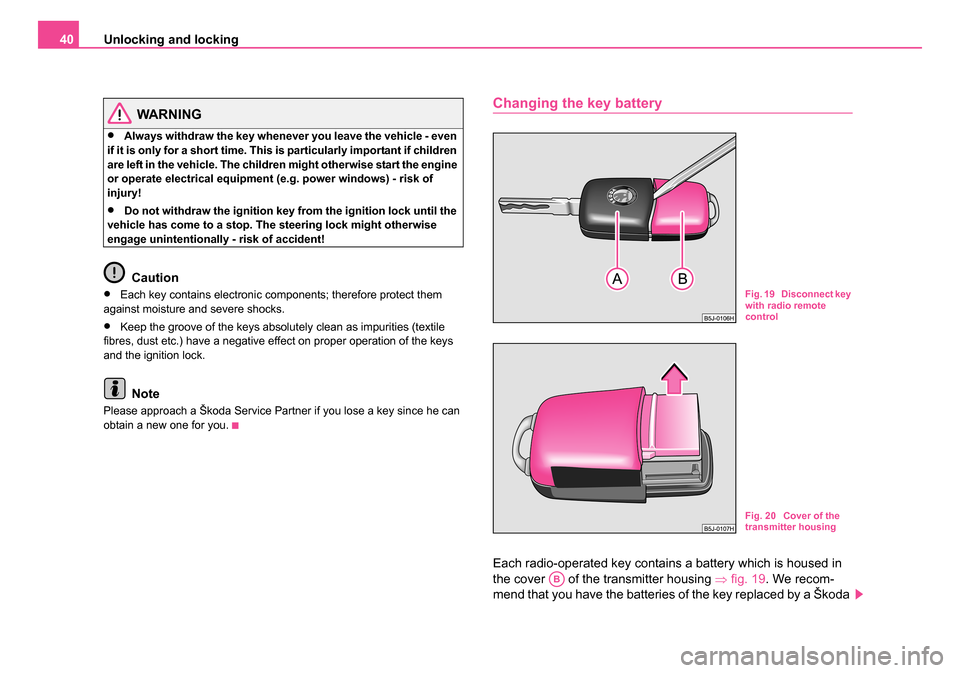
Each radio-operated key contains a battery which is housed in
the cover of the transmitter housing ⇒fig. 19 . We recom-
mend that you have the batteries of the key replaced by a Škoda
Fig. 19 Disconnect key
with radio remote
control
Fig. 20 Cover of the
transmitter housing
AB
NKO 20 A05.book Page 40 Wednesday, June 21, 2006 1:42 PM
Page 42 of 274
Unlocking and locking41
Using the systemSafetyDriving TipsGeneral MaintenanceBreakdown assistanceTechnical Data
Service Partner. You should, however, proceed as follows if you
wish to replace the battery yourself:
– Fold open the key.
– Use a screwdriver to carefully lever off the front part of the key
⇒ page 40, fig. 19 from the transmitter housing .
– Take off the cover of the transmitter housing ⇒page 40,
fig. 20 in direction of arrow.
– Take the used battery out of the housing cover.
– Insert the new battery. Ensure that the “+” symbol on the battery is facing downwards. The correct polarity is also
shown on the cover of the transmitter housing.
– Insert cover with battery in place at the rear of the transmitter housing and press both parts together.
– Insert the transmitter housing into the front part of the key so that the two parts lock into each other.
For the sake of the environment
Dispose of an old battery in accordance with environmental regulations.
Note
•The replacement battery must have the same specification as the orig-
inal battery.
•If it is still not be possible to unlock or lock the vehicle with the remote
control even after replacing the battery this means that the system has to
be synchronised ⇒page 49.
Electronic immobiliser
The electronic immobiliser prevents the vehicle being
operated by an unauthorised person.
An electronic chip is integrated in the head of the key. The immobiliser is
deactivated with the aid of this chip when the key is inserted in the ignition
lock. The electronic immobiliser is automatically activated when you with-
draw the ignition key from the lock.
Note
It is only possible to start the engine of your car with a Genuine Škoda key
with the matching code ⇒page 32.
Locking
Valid for vehicles without a central locking system:
Locking from outside
The securing head will move upwards or downwards in the door when
unlocking or locking.
Locking from inside
All closed vehicle doors are locked by pressing in the securing knobs from
the inside. The doors cannot be opened from the outside when the
securing knobs have been pressed in. The vehicle doors can be opened
from the inside as follows:
•The door is unlocked by actuating the door-opening lever.
•The door opens upon actuating the door-opening lever again.
AAAB
NKO 20 A05.book Page 41 Wednesday, June 21, 2006 1:42 PM