fuse SKODA ROOMSTER 2006 1.G Owner's Manual
[x] Cancel search | Manufacturer: SKODA, Model Year: 2006, Model line: ROOMSTER, Model: SKODA ROOMSTER 2006 1.GPages: 274, PDF Size: 48.64 MB
Page 7 of 274
Contents
6
Airbag system. . . . . . . . . . . . . . . . . . . . . . . . .
Description of the airbag system . . . . . . . . . .
Front airbags . . . . . . . . . . . . . . . . . . . . . . . . .
Side airbags* . . . . . . . . . . . . . . . . . . . . . . . . .
Head airbags* . . . . . . . . . . . . . . . . . . . . . . . .
Deactivating an airbag . . . . . . . . . . . . . . . . . .
Transporting children safely. . . . . . . . . . . . .
What you should know about transporting
children! . . . . . . . . . . . . . . . . . . . . . . . . . . . . .
Child seat . . . . . . . . . . . . . . . . . . . . . . . . . . . .
Attaching a child seat using the “ISOFIX”
system* . . . . . . . . . . . . . . . . . . . . . . . . . . . . .
Attaching child seat using the “Top Tether”
system . . . . . . . . . . . . . . . . . . . . . . . . . . . . . .
Driving Tips . . . . . . . . . . . . . . . . . . . . . .
Intelligent Technology . . . . . . . . . . . . . . . . . .
Electronic stability programme (ESP)* . . . . . .
Brakes . . . . . . . . . . . . . . . . . . . . . . . . . . . . . .
Brake booster . . . . . . . . . . . . . . . . . . . . . . . .
Antilock brake system (ABS)* . . . . . . . . . . . .
Brake Assist* . . . . . . . . . . . . . . . . . . . . . . . . .
Power steering* . . . . . . . . . . . . . . . . . . . . . . .
Tyre inflation pressure-control system* . . . . .
Driving and the Environment. . . . . . . . . . . .
The first 1 500 kilometres and then afterwards
Catalytic converter . . . . . . . . . . . . . . . . . . . . .
Driving in an economical and environmentally
conscious manner . . . . . . . . . . . . . . . . . . . . .
Environmental compatibility . . . . . . . . . . . . . .
Motoring abroad . . . . . . . . . . . . . . . . . . . . . . .
Avoiding damage to your vehicle . . . . . . . . . .
Towing a trailer . . . . . . . . . . . . . . . . . . . . . . . .
Towing a trailer . . . . . . . . . . . . . . . . . . . . . . . .
General Maintenance. . . . . . . . . .
Taking care of your vehicle and cleaning the
vehicle . . . . . . . . . . . . . . . . . . . . . . . . . . . . . . .
General . . . . . . . . . . . . . . . . . . . . . . . . . . . . .
Care of the exterior of vehicle . . . . . . . . . . . .
Care of the interior of vehicle . . . . . . . . . . . . .
Fuel. . . . . . . . . . . . . . . . . . . . . . . . . . . . . . . . . .
Petrol . . . . . . . . . . . . . . . . . . . . . . . . . . . . . . .
Diesel . . . . . . . . . . . . . . . . . . . . . . . . . . . . . .
Refuelling . . . . . . . . . . . . . . . . . . . . . . . . . . .
Inspecting and Replenishing. . . . . . . . . . . .
Engine compartment . . . . . . . . . . . . . . . . . . . . . . . . . . . . . . . . . . . . . . . . . . . . . . . . . . . . . .
Cooling system . . . . . . . . . . . . . . . . . . . . . . .
Brake fluid . . . . . . . . . . . . . . . . . . . . . . . . . . .
Battery . . . . . . . . . . . . . . . . . . . . . . . . . . . . . .
Windshield washer system . . . . . . . . . . . . . .
Wheels and Tyres . . . . . . . . . . . . . . . . . . . . .
Wheels . . . . . . . . . . . . . . . . . . . . . . . . . . . . .
Accessories, changes and replacement of
parts . . . . . . . . . . . . . . . . . . . . . . . . . . . . . . . . .
Accessories and replacement parts . . . . . . .
Technical changes . . . . . . . . . . . . . . . . . . . . .
Breakdown assistance . . . . . . . .
Breakdown assistance . . . . . . . . . . . . . . . . .
First-aid box* and Warning triangle* . . . . . . .
Fire extinguisher* . . . . . . . . . . . . . . . . . . . . . .
Vehicle tool kit . . . . . . . . . . . . . . . . . . . . . . . .
Tyre repair kit* . . . . . . . . . . . . . . . . . . . . . . . .
Spare wheel* . . . . . . . . . . . . . . . . . . . . . . . . .
Changing a wheel . . . . . . . . . . . . . . . . . . . . .
Jump-starting . . . . . . . . . . . . . . . . . . . . . . . . .
Tow-starting and towing vehicle . . . . . . . . . . .
Fuses and light bulbs . . . . . . . . . . . . . . . . . .
Electric fuses . . . . . . . . . . . . . . . . . . . . . . . . .
Bulbs . . . . . . . . . . . . . . . . . . . . . . . . . . . . . . .
Te c h n i c a l D a ta . . . . . . . . . . . . . . . . . .
General . . . . . . . . . . . . . . . . . . . . . . . . . . . . . .
Identification data . . . . . . . . . . . . . . . . . . . . .
Index . . . . . . . . . . . . . . . . . . . . . . . . . . . . . .
154
154
156
159
161
163
166
166
170
174
175
177
177
177
180
181
181
182
183
183
185
185
186
187
191
192
192
193
193 197
197
197
197
203
205
205
205
207
209
209
212
215
218
220
224
225
225
232
232
232
235
235
235
235
236
236
237
237
243
245249
249
254
263
263
263
265
NKO 20 A05.book Page 6 Wednesday, June 21, 2006 1:42 PM
Page 12 of 274
Cockpit11
Using the systemSafetyDriving TipsGeneral MaintenanceBreakdown assistanceTechnical Data
Cockpit
General view
This general view is designed to help you to quickly
become familiar with the instruments, gauges and
controls.
Electric power-operated window* . . . . . . . . . . . . . . . . . . . .
Electric exterior mirror adjustment* . . . . . . . . . . . . . . . . . . .
Air outlet vents . . . . . . . . . . . . . . . . . . . . . . . . . . . . . . . . . . .
Multi-functional module* . . . . . . . . . . . . . . . . . . . . . . . . . . .
Lever for the multi-functional switch:
−Turn signal light, headlight and parking light, headlight
flasher . . . . . . . . . . . . . . . . . . . . . . . . . . . . . . . . . . . . . . .
− Speed regulating system* . . . . . . . . . . . . . . . . . . . . . . . .
Headlight flasher, driver airbag . . . . . . . . . . . . . . . . . . . . . .
Instrument cluster: Instruments and indicator lights . . . . . .
Lever for the multi-functional switch:
− Multi-functional indicator* . . . . . . . . . . . . . . . . . . . . . . . .
− Windshield wiper and wash system . . . . . . . . . . . . . . . . .
Switch for rear window heater . . . . . . . . . . . . . . . . . . . . . . .
Depending on equipment fitted:
− Switch for the ESP* . . . . . . . . . . . . . . . . . . . . . . . . . . . . .
− Switch for the TCS* . . . . . . . . . . . . . . . . . . . . . . . . . . . . .
Air outlet vents . . . . . . . . . . . . . . . . . . . . . . . . . . . . . . . . . . .
Switch for hazard warning lights . . . . . . . . . . . . . . . . . . . . .
Indicator light for a switched off front seat passenger airbag*
Depending on equipment fitted:
− Operating controls for the heating . . . . . . . . . . . . . . . . . . −
Operating controls for Climatic* . . . . . . . . . . . . . . . . . . .
− Operating controls for Climatronic* . . . . . . . . . . . . . . . .
Storage compartments on the front passenger side* . . . . .
Front passenger airbag* . . . . . . . . . . . . . . . . . . . . . . . . . . .
Switch for the front seat passenger airbag(s)* . . . . . . . . . .
Switch depending on equipment fitted:
− Unlock tailgate* . . . . . . . . . . . . . . . . . . . . . . . . . . . . . . . .
− Interior monitor* . . . . . . . . . . . . . . . . . . . . . . . . . . . . . . .
Fuse box in the dash panel . . . . . . . . . . . . . . . . . . . . . . . .
Light switch and control dial for the headlight beam range
regulation . . . . . . . . . . . . . . . . . . . . . . . . . . . . . . . . . . . . . .
Bonnet release lever . . . . . . . . . . . . . . . . . . . . . . . . . . . . . .
Lever for adjusting the steering wheel . . . . . . . . . . . . . . . .
Ignition lock . . . . . . . . . . . . . . . . . . . . . . . . . . . . . . . . . . . . .
Radio*
Rocker switch for heating on the driver's seat* . . . . . . . . .
Buttons for central locking* . . . . . . . . . . . . . . . . . . . . . . . . .
Depending on equipment fitted:
− Gearshift lever (manual gearbox) . . . . . . . . . . . . . . . . . .
− Selector lever (6-speed automatic gearbox)* . . . . . . . . .
Rocker switch for heating on the front passenger seat* . . .
Depending on equipment fitted:
− Ashtray* . . . . . . . . . . . . . . . . . . . . . . . . . . . . . . . . . . . . .
− Storage compartment . . . . . . . . . . . . . . . . . . . . . . . . . . .
CD changer* . . . . . . . . . . . . . . . . . . . . . . . . . . . . . . . . . . . . A151
A266
A398
A4126
A5
59
11 6
A6156
A713
A8
17
63
A962
A10
177
178
A1198
A1259
A13164
A14
96 99
104
A1590
A16156
A17164
A18
46
50
A19249
A2055, 58
A21209
A22109
A2311 0
A24
A2571
A2645
A27
11 3
120
A2871
A29
87
92
A30139
NKO 20 A05.book Page 11 Wednesday, June 21, 2006 1:42 PM
Page 32 of 274
Instruments and Indicator/Warning Lights31
Using the systemSafetyDriving TipsGeneral MaintenanceBreakdown assistanceTechnical Data
an emergency programme which enables you to drive to the nearest
specialist garage by adopting a gentle style of driving.
The following text will be displayed in the information display*:
ENGINE FAULT WORKSHOP!
Turn signal system for vehicles towing a trailer*
The indicator light on vehicles towing a trailer flashes together with the
respective indicator light for the turn signal system.
The indicator light
does not flash if a turn signal light on the trailer or
on the vehicle is not operating.
Coolant temperature/coolant level
The warning light comes on for a few seconds 1) when the ignition is
switched on.
The coolant temperature is too high or the coolant level too low if the
warning light
does not go out after the engine is started or flashes while
driving.
3 peeps sound as an additional warning signal.
In this case stop and switch the engine off and check the coolant level;
top up the coolant as necessary ⇒page 217, “Replenishing the coolant”.
Do not continue your journey if for some reason it is not possible under
the conditions prevailing to top up with coolant. Keep the engine switched off
and obtain professional assistance from a specialist garage,
otherwise it could lead to severe engine damage.
If the coolant is within the specified range, the increased temperature may
be caused by an operating problem at the coolant fan. Check the fuse for
the coolant fan, replace it if necessary ⇒page 253, “Fuse assignment at
battery”.
Do not continue driving if the warning light does not go off although the
fluid is at the correct level and also the fuse of the fan is in proper order.
Contact a specialist garage to obtain assistance.
Please also refer to the additional instructions ⇒page 215, “Cooling
system”.
The following text will be displayed in the information display*:
STOP CHECK COOLANT OWNER'S MANUAL!
WARNING
•If you must stop for technical reasons, then park the vehicle at
a safe distance from the traffic and switch off the engine and switch
on the hazard warning light system ⇒page 59, “Switch for hazard
warning lights ”.
•Pay attention to the following instructions ⇒page 210,
“Working in the engine compartment” before checking the coolant
fluid level and opening the bonnet.
•Take care when opening the coolant expansion bottle. If the
engine is hot, the cooling system is pressurized - risk of scalding.
It is best to allow the engine to cool down before removing the cap.
•Do not touch the coolant fan! The coolant fan may switch on
automatically even if the ignition is off.
1)The warning light on vehicles fitted with information display does not come on
after switching the ignition on, but only if the coolant temperature is to\
o high or the
coolant level is too low.
NKO 20 A05.book Page 31 Wednesday, June 21, 2006 1:42 PM
Page 56 of 274
Lights and Visibility55
Using the systemSafetyDriving TipsGeneral MaintenanceBreakdown assistanceTechnical Data
Lights and Visibility
Lights
Switching lights on and off
Switching on side lights
– Turn the light switch ⇒fig. 32 into position
.
Switching on the low beam and main beam
– Turn the light switch into position
.
– Press the main beam lever forward in order to switch on the main beam ⇒page 59, fig. 37 .
Switching off all lights
– Turn the light switch into position O.
Switching on daylight driving lights*
– Remove the cover of the fuse box on the left side of the dash panel ⇒page 249.
Fig. 32 Dash panel:
Light switch
Fig. 33 Fuse box:
Switch for daylight
driving lights
NKO 20 A05.book Page 55 Wednesday, June 21, 2006 1:42 PM
Page 104 of 274
Heating and air conditioning system 103
Using the systemSafetyDriving TipsGeneral MaintenanceBreakdown assistanceTechnical Data
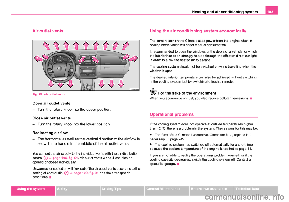
Air outlet vents
Fig. 95 Air outlet vents
Open air outlet vents
– Turn the rotary knob into the upper position.
Close air outlet vents
– Turn the rotary knob into the lower position.
Redirecting air flow
– The horizontal as well as the vertical direction of the air flow is
set with the handle in the middle of the air outlet vents.
You can set the air supply to the individual vents with the air distribution
control ⇒page 100, fig. 94 . Air outlet vents 3 and 4 can also be
opened or closed individually:
Unwarmed or cooled air will flow out of the air outlet vents according to the
setting of control dial ⇒page 100, fig. 94 and the atmospheric
conditions.
Using the air conditioni ng system economically
The compressor on the Climatic uses power from the engine when in
cooling mode which will effect the fuel consumption.
It recommended to open the windows or the doors of a vehicle for which
the interior has been strongly heated through the effect of direct sunlight
in order to allow the heated air to escape.
The cooling system should not be switched on while travelling when the
window is open.
The desired interior temperature can also be achieved without switching
in the cooling system just by switching to fresh air mode.
For the sake of the environment
When you economize on fuel, you also reduce pollutant emissions.
Operational problems
If the cooling system does not operate at outside temperatures higher
than +2 °C, there is a problem in the system. The reasons for this may be:
•The fuse of the Climatic is defective. Check the fuse, replace it if
necessary ⇒page 249.
•The cooling system has switched off automatically for a short time
because the coolant temperature of the engine is too hot ⇒page 14.
If you are not able to rectify the operational problem yourself, or if the
cooling capacity decreases, switch the cooling system off. Contact a
specialist garage.
AC
AA
NKO 20 A05.book Page 103 Wednesday, June 21, 2006 1:42 PM
Page 113 of 274
Starting-off and Driving
112
For the sake of the environment
Never warm up the engine when the vehicle is standing. Drive off right
away. When driving the engine reaches its operating temperature more
rapidly and the pollutant emissions are lower.
Petrol engines
These engines are fitted with a starter system which selects the correct
fuel/air mixture for every external air temperature.
•Do not operate accelerator before and when starting engine.
•Interrupt the attempt at starting after 10 seconds if the engine does not
start right awayand wait for about 30 seconds before repeating the
attempt.
•It is possible that the fuse on the electrical fuel pump is defect if the
engine still does not start. Check the fuse and replace it if necessary
⇒ page 249.
•If the engine does not start, contact the nearest specialist garage to
obtain professional assistance.
It may be necessary, if the engine is very hot, to slightly depress the
accelerator after the engine has started.
Diesel engines
Glow plug system
Diesel engines are equipped with a glow plug system, the preglow period
being controlled automatically in line with the coolant temperature and
outside temperature. The preglow indicator light
comes on after the ignition has been
switched on.
You should not switch on any major electrical components during
the heating period otherwise the vehicle battery will be drained
unnecessarily.
•You should start the engine immediately after the glow plug warning
light has gone out.
•The glow plug warning light will come on for about one second if the
engine is at a normal operating temperature or if the outside temperature
is above +5°C. This means that you can start the engine right away.
•Interrupt the attempt at starting after 10 seconds if the engine does not
start right awayand wait for about 30 seconds before repeating the
attempt.
•It is possible that the fuse on the diesel preglow system is defect if the
engine still does not start. Check the fuse and replace it if necessary
⇒ page 249.
•Contact the nearest specialist garage to obtain professional assist-
ance.
Starting the engine after fuel tank has run dry
It may take longer than normal to start the engine after refuelling if the fuel
tank has run completely dry - up to one minute. This is because the fuel
system must first of all be filled while the attempting to start the engine.
Switching off the engine
– The engine can be switched off by turning the ignition key from position ⇒page 110, fig. 100 into position .
A1
NKO 20 A05.book Page 112 Wednesday, June 21, 2006 1:42 PM
Page 125 of 274
Automatic gearbox
124
If you select a lower gear, the automatic gearbox does not shift down until
there is no risk of the engine overrevving. (Does not apply for the shifting
from 2nd to 1st gear.)
If you operate the kickdown function, the gearbox shifts into a lower gear
in line with the vehicle speed and engine speed.
Emergency programme
An emergency programme exists in the event of a fault in
the system.
The gearbox operates in a corresponding emergency programme if there
are functional faults in the gearbox electronics. This is indicated by all of
the segments in the display lighting up or going out.
It is possible to continue to move the selector lever into all the positions.
In the positions D and S the gearbox remains engaged in the 3rd gear. It
is also possible to continue to engage reverse gear in the position R.
The manual shift programme (Tiptronic) is switched off in the emergency
mode.
If the gearbox has switched over to emergency mode, drive to the
nearest specialist garage in order to have the fault rectified.
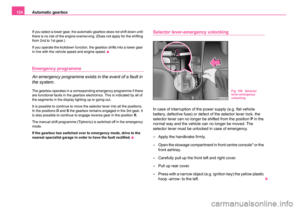
Selector lever-emergency unlocking
In case of interruption of the power supply (e.g. flat vehicle
battery, defective fuse) or defect of the selector lever lock, the
selector lever can no longer be shifted from the position P in the
normal way and the vehicle can no longer be moved. The
selector lever must be unlocked in case of emergency.
– Apply the handbrake firmly.
– Open the stowage compartment in front centre console* or the front ashtray.
– Carefully pull up the front left and right cover.
– Pull up rear cover.
– Press with a narrow object (e.g. ignition key) the yellow plastic hoop -arrow- to the left.
Fig. 109 Selector
lever-emergency
unlocking
NKO 20 A05.book Page 124 Wednesday, June 21, 2006 1:42 PM
Page 210 of 274
Inspecting and Replenishing209
Using the systemSafetyDriving TipsGeneral MaintenanceBreakdown assistanceTechnical Data
Inspecting and Replenishing
Engine compartment
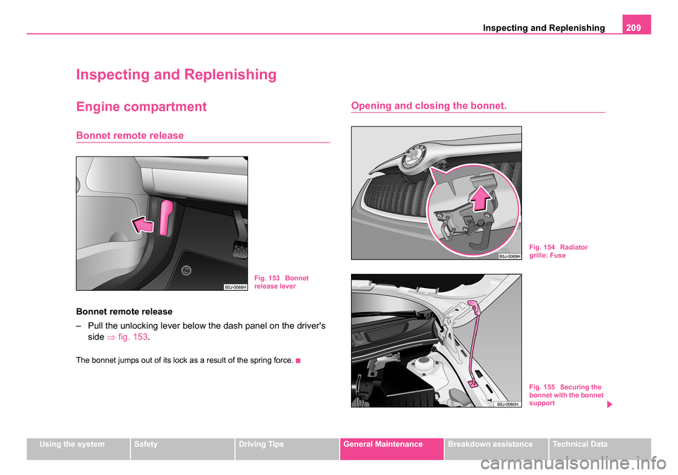
Bonnet remote release
Bonnet remote release
– Pull the unlocking lever below the dash panel on the driver's
side ⇒fig. 153 .
The bonnet jumps out of its lock as a result of the spring force.
Opening and closing the bonnet.
Fig. 153 Bonnet
release lever
Fig. 154 Radiator
grille: Fuse
Fig. 155 Securing the
bonnet with the bonnet
support
NKO 20 A05.book Page 209 Wednesday, June 21, 2006 1:42 PM
Page 221 of 274
Inspecting and Replenishing
220
Battery
Working on the battery
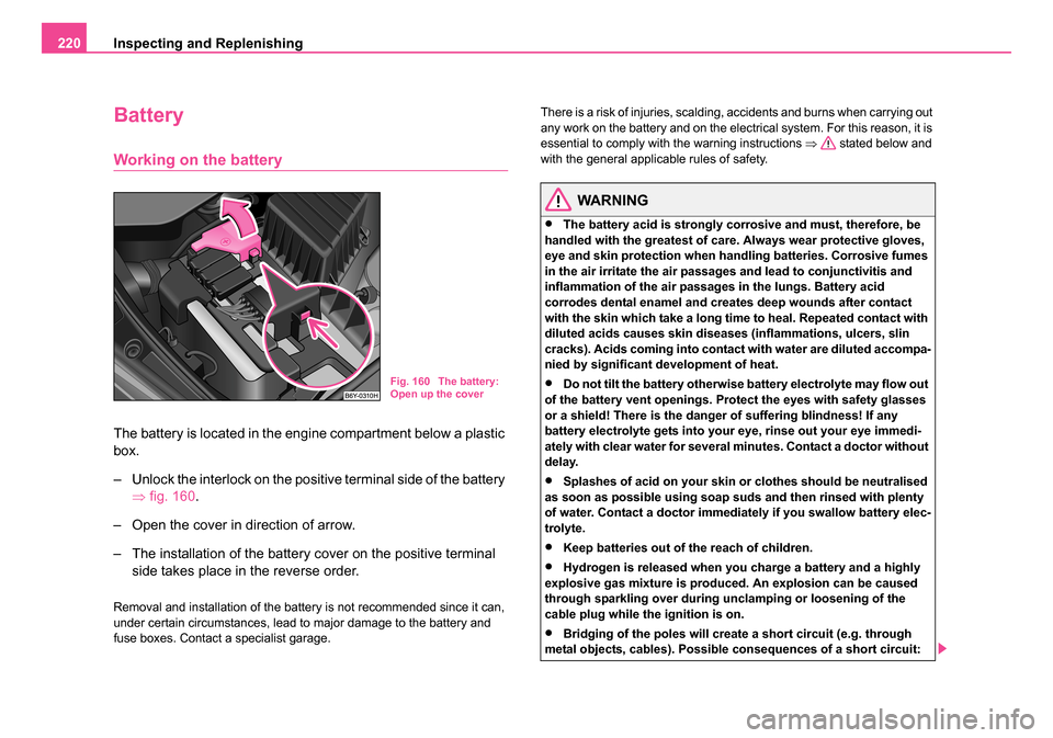
The battery is located in the engine compartment below a plastic
box.
– Unlock the interlock on the positive terminal side of the battery
⇒fig. 160 .
– Open the cover in direction of arrow.
– The installation of the battery cover on the positive terminal side takes place in the reverse order.
Removal and installation of the battery is not recommended since it can,
under certain circumstances, lead to major damage to the battery and
fuse boxes. Contact a specialist garage. There is a risk of injuries, scalding, accidents and burns when carrying out
any work on the battery and on the electrical system. For this reason, it is
essential to comply with the warning instructions
⇒ stated below and
with the general applicable rules of safety.
WARNING
•The battery acid is strongly corrosive and must, therefore, be
handled with the greatest of care. Always wear protective gloves,
eye and skin protection when handling batteries. Corrosive fumes
in the air irritate the air passages and lead to conjunctivitis and
inflammation of the air passages in the lungs. Battery acid
corrodes dental enamel and creates deep wounds after contact
with the skin which take a long time to heal. Repeated contact with
diluted acids causes skin diseases (inflammations, ulcers, slin
cracks). Acids coming into contact with water are diluted accompa-
nied by significant development of heat.
•Do not tilt the battery otherwise battery electrolyte may flow out
of the battery vent openings. Protect the eyes with safety glasses
or a shield! There is the danger of suffering blindness! If any
battery electrolyte gets into your eye, rinse out your eye immedi-
ately with clear water for several minutes. Contact a doctor without
delay.
•Splashes of acid on your skin or clothes should be neutralised
as soon as possible using soap suds and then rinsed with plenty
of water. Contact a doctor immediately if you swallow battery elec-
trolyte.
•Keep batteries out of the reach of children.
•Hydrogen is released when you charge a battery and a highly
explosive gas mixture is produced. An explosion can be caused
through sparkling over during unclamping or loosening of the
cable plug while the ignition is on.
•Bridging of the poles will create a short circuit (e.g. through
metal objects, cables). Possible consequences of a short circuit:
Fig. 160 The battery:
Open up the cover
NKO 20 A05.book Page 220 Wednesday, June 21, 2006 1:42 PM
Page 250 of 274
Fuses and light bulbs249
Using the systemSafetyDriving TipsGeneral MaintenanceBreakdown assistanceTechnical Data
Fuses and light bulbs
Electric fuses
Replacing fuses in the dash panel
Defect fuses must be replaced.
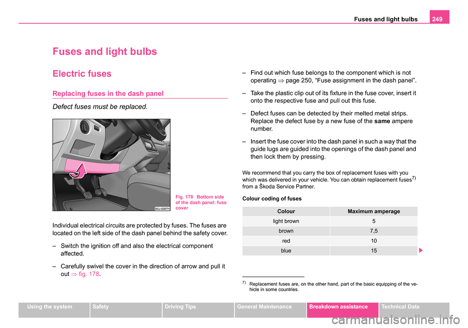
Individual electrical circuits are protected by fuses. The fuses are
located on the left side of the dash panel behind the safety cover.
– Switch the ignition off and also the electrical component
affected.
– Carefully swivel the cover in the direction of arrow and pull it out ⇒fig. 178 . – Find out which fuse belongs to the component which is not
operating ⇒page 250, “Fuse assignment in the dash panel”.
– Take the plastic clip out of its fixture in the fuse cover, insert it onto the respective fuse and pull out this fuse.
– Defect fuses can be detected by their melted metal strips. Replace the defect fuse by a new fuse of the same ampere
number.
– Insert the fuse cover into the dash panel in such a way that the guide lugs are guided into the openings of the dash panel and
then lock them by pressing.
We recommend that you carry the box of replacement fuses with you
which was delivered in your vehicle. You can obtain replacement fuses7)
from a Škoda Service Partner.
Colour coding of fuses
Fig. 178 Bottom side
of the dash panel: fuse
cover
7)Replacement fuses are, on the other hand, part of the basic equipping of the ve-
hicle in some countries.
ColourMaximum amperage
light brown5
brown7,5
red10
blue15
NKO 20 A05.book Page 249 Wednesday, June 21, 2006 1:42 PM