ECO mode SKODA ROOMSTER 2007 1.G Owner's Manual
[x] Cancel search | Manufacturer: SKODA, Model Year: 2007, Model line: ROOMSTER, Model: SKODA ROOMSTER 2007 1.GPages: 248, PDF Size: 46.44 MB
Page 2 of 248
Introduction
You have opted for a Škoda - our sincere thanks for your confidence in us.
Your new Škoda offers you a vehicle fe aturing the most modern engineering and a wide range of equipment which
you will undoubtedly wish to use to the full during your daily motoring. That is why, we recommend that you read
this Owner's Manual attentively to enable you to become fami liar with your car and all that it offers as quickly as
possible.
Please do not hesitate to contact your Škoda Service Pa rtner or importer should you have any further questions
regarding any problems which may arise or your vehicle. He will be ready at any time to receive your questions,
suggestions and criticisms.
Any national legal provisions which vary from the inform ation contained in this Owner's Manual take precedence
over the information contained herein.
We wish you much pleasure with your Šk oda and pleasant motoring at all times.
Yo u r Škoda Auto
NKO A05R 20 MR08.book Page 1 Wednesday, March 28, 2007 9:42 AM
Page 3 of 248
Introduction2
On-board literature
The on-board literature for your vehicle consists of this “ Owner's
Manual ” as well as the brochures “Quick Reference Guide”, “Service
Schedule ” and “Help on the road”. There can also be a variety of other
additional operating manuals and instructions on-board (e.g. an oper-
ating manual for the radio) dependin g on the vehicle model and equip-
ment.
If one of the publications listed above is missing, please contact a Škoda
Service Partner immediately, where one wi ll be glad to assist you in such
matters.
One should note that the details give n in the vehicle's papers always
take precedence over those in the Owner's Manual.
Owner's Manual
This Owner's Manual describes the current scope of equipment.
Certain items of equipment listed ar e only installed later on and only
envisaged for particular markets. The illustrations can differ in minor
details from your vehicle; they are only intended for general information.
In addition to information regarding all the controls and equipment, the
Owner's Manual also contains import ant information regarding care and
operation for your safety and also to retain the value of your vehicle. To
provide you with valuable tips and aids. You can learn how how you can
operate your vehicle safely, economically and in an environmentally
conscious way.
For safety reasons, please also pay attention to the information on
accessories, modifications and replacement of parts ⇒page 193.
The other chapters of the Owner's Manual are also important, however,
for proper treatment of your car - in addition to regular care and mainte-
nance - helps to retain its value and in many cases is also one of the
conditions for possible warranty claims.
The Brief instruction
includes an overview of the most important controls of your vehicle.
The Service schedule
contains:
•Vehicle data,
•Service intervals,
•Overview of the service work,
•Service proof,
•Confirmation of mo bility warranty,
•important information on the warranty.
The confirmations of the carried out service work are one of the condi-
tions for possible warranty claims.
Please always present th e Service schedule when you take your car to a
Škoda Service Partner.
If the Service schedule is missing or worn, please contact your Škoda
Service Partner, where your car is serviced regularly. You will receive a
duplicate, in which the previously carried out service work are confirmed.
Help on the road
contains the addresses and telephone numbers of Škoda Importers.
NKO A05R 20 MR08.book Page 2 Wednesday, March 28, 2007 9:42 AM
Page 9 of 248
Cockpit8
Cockpit
General view
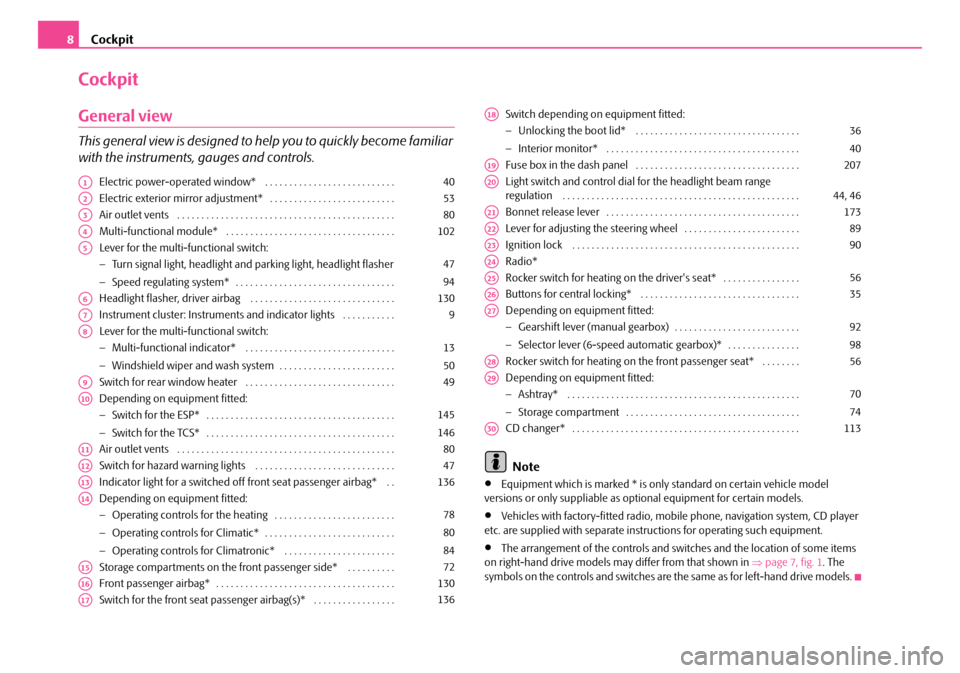
This general view is designed to help you to quickly become familiar
with the instruments, gauges and controls.
Electric power-operated window* . . . . . . . . . . . . . . . . . . . . . . . . . . .
Electric exterior mirror adjustment* . . . . . . . . . . . . . . . . . . . . . . . . . .
Air outlet vents . . . . . . . . . . . . . . . . . . . . . . . . . . . . . . . . . . . . . . . . . . . . .
Multi-functional module* . . . . . . . . . . . . . . . . . . . . . . . . . . . . . . . . . . .
Lever for the multi-functional switch:
− Turn signal light, headlight and parking light, headlight flasher
− Speed regulating system* . . . . . . . . . . . . . . . . . . . . . . . . . . . . . . . . .
Headlight flasher, driver airbag . . . . . . . . . . . . . . . . . . . . . . . . . . . . . .
Instrument cluster: Instruments and in dicator lights . . . . . . . . . . .
Lever for the multi-functional switch:
− Multi-functional indicator* . . . . . . . . . . . . . . . . . . . . . . . . . . . . . . .
− Windshield wiper and wash system . . . . . . . . . . . . . . . . . . . . . . . .
Switch for rear window heater . . . . . . . . . . . . . . . . . . . . . . . . . . . . . . .
Depending on equipment fitted:
− Switch for the ESP* . . . . . . . . . . . . . . . . . . . . . . . . . . . . . . . . . . . . . . .
− Switch for the TCS* . . . . . . . . . . . . . . . . . . . . . . . . . . . . . . . . . . . . . . .
Air outlet vents . . . . . . . . . . . . . . . . . . . . . . . . . . . . . . . . . . . . . . . . . . . . .
Switch for hazard warning lights . . . . . . . . . . . . . . . . . . . . . . . . . . . . .
Indicator light for a switched off front seat passenger airbag* . .
Depending on equipment fitted:
− Operating controls for the heating . . . . . . . . . . . . . . . . . . . . . . . . .
− Operating controls for Climatic* . . . . . . . . . . . . . . . . . . . . . . . . . . .
− Operating controls for Climatronic* . . . . . . . . . . . . . . . . . . . . . . .
Storage compartments on the front passenger side* . . . . . . . . . .
Front passenger airbag* . . . . . . . . . . . . . . . . . . . . . . . . . . . . . . . . . . . . .
Switch for the front seat passenger airbag(s)* . . . . . . . . . . . . . . . . .
Switch depending on equipment fitted:
− Unlocking the boot lid* . . . . . . . . . . . . . . . . . . . . . . . . . . . . . . . . . .
− Interior monitor* . . . . . . . . . . . . . . . . . . . . . . . . . . . . . . . . . . . . . . . .
Fuse box in the dash panel . . . . . . . . . . . . . . . . . . . . . . . . . . . . . . . . . .
Light switch and control dial for the headlight beam range regulation . . . . . . . . . . . . . . . . . . . . . . . . . . . . . . . . . . . . . . . . . . . . . . . . .
Bonnet release lever . . . . . . . . . . . . . . . . . . . . . . . . . . . . . . . . . . . . . . . .
Lever for adjusting the steering wheel . . . . . . . . . . . . . . . . . . . . . . . .
Ignition lock . . . . . . . . . . . . . . . . . . . . . . . . . . . . . . . . . . . . . . . . . . . . . . .
Radio*
Rocker switch for heating on the driver's seat* . . . . . . . . . . . . . . . .
Buttons for central locking* . . . . . . . . . . . . . . . . . . . . . . . . . . . . . . . . .
Depending on equipment fitted:
− Gearshift lever (manual gearbox) . . . . . . . . . . . . . . . . . . . . . . . . . .
− Selector lever (6-speed automatic gearbox)* . . . . . . . . . . . . . . .
Rocker switch for heating on the front passenger seat* . . . . . . . .
Depending on equipment fitted:
− Ashtray* . . . . . . . . . . . . . . . . . . . . . . . . . . . . . . . . . . . . . . . . . . . . . . . .
− Storage compartment . . . . . . . . . . . . . . . . . . . . . . . . . . . . . . . . . . . .
CD changer* . . . . . . . . . . . . . . . . . . . . . . . . . . . . . . . . . . . . . . . . . . . . . . .
Note
•Equipment which is marked * is only standard on certain vehicle model versions or only suppliable as optional equipment for certain models.
•Vehicles with factory-fitted radio, mobi le phone, navigation system, CD player etc. are supplied with separate inst ructions for operating such equipment.
•The arrangement of the controls and switches and the location of some items on right-hand drive models may differ from that shown in ⇒page 7, fig. 1. The symbols on the controls and switches are the same as for left-hand drive models.
A140
A253
A380
A4102
A5
47
94
A6130
A79
A8
13
50
A949
A10
145
146
A1180
A1247
A13136
A14
78
80
84
A1572
A16130
A17136
A18
36
40
A19207
A2044, 46
A21173
A2289
A2390
A24
A2556
A2635
A27
92
98
A2856
A29
70
74
A30113
NKO A05R 20 MR08.book Page 8 Wednesday, March 28, 2007 9:42 AM
Page 12 of 248
Instruments and Indicator/Warning Lights11
Using the systemSafetyDriving TipsGeneral MaintenanceBreakdown assistancePraktikTechnical Data
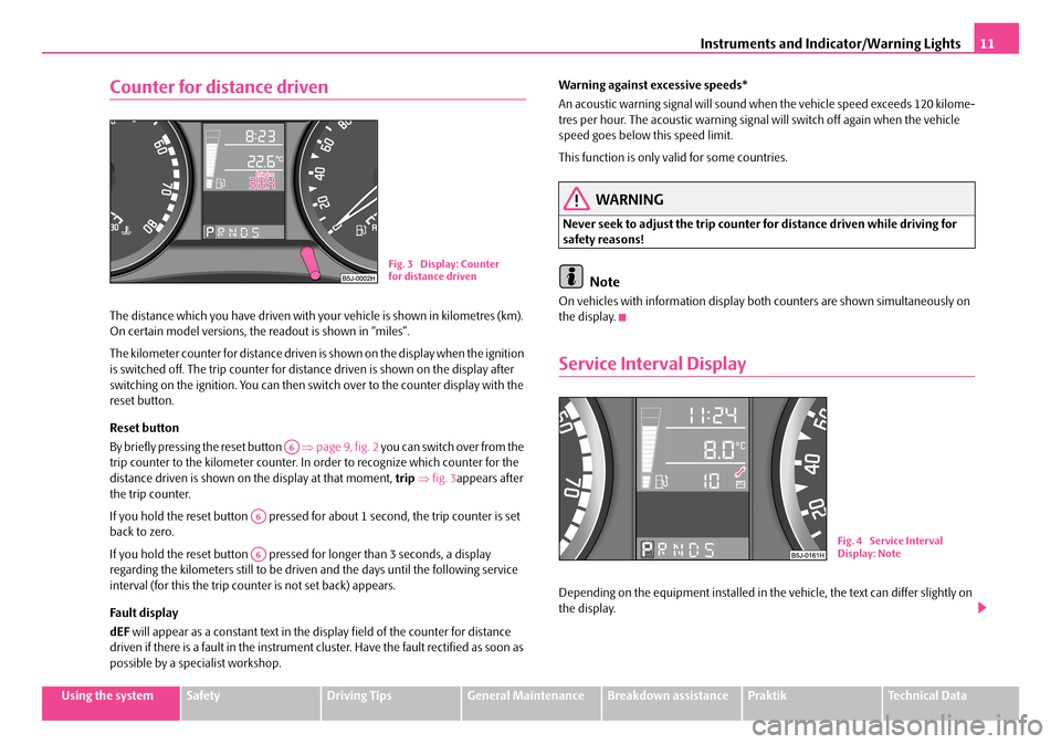
Counter for distance driven
The distance which you have driven with your vehicle is shown in kilometres (km). On certain model versions, the readout is shown in “miles”.
The kilometer counter for distance driven is shown on the display when the ignition is switched off. The trip counter for dist ance driven is shown on the display after switching on the ignition. You can then swit ch over to the counter display with the reset button.
Reset button
By briefly pressing the reset button ⇒page 9, fig. 2 you can switch over from the trip counter to the kilometer counter. In order to recognize which counter for the distance driven is shown on the display at that moment, trip ⇒fig. 3appears after the trip counter.
If you hold the reset button pressed for about 1 second, the trip counter is set back to zero.
If you hold the reset button pressed for longer than 3 seconds, a display regarding the kilometers still to be driven and the days until the following service interval (for this the trip counter is not set back) appears.
Fa ult di spl a y
dEF will appear as a constant text in the display field of the counter for distance driven if there is a fault in the instrument cluster. Have the fault rectified as soon as possible by a specialist workshop.
Warning against excessive speeds*
An acoustic warning signal will sound when the vehicle speed exceeds 120 kilome- tres per hour. The acoustic warning signal will switch off again when the vehicle speed goes below this speed limit.
This function is only valid for some countries.
WARNING
Never seek to adjust the trip counter for distance driven while driving for safety reasons!
Note
On vehicles with information display bo th counters are shown simultaneously on the display.
Service Interval Display
Depending on the equipment installed in the vehicle, the text can differ slightly on the display.
Fig. 3 Display: Counter for distance driven
A6
A6
A6Fig. 4 Service Interval Display: Note
NKO A05R 20 MR08.book Page 11 Wednesday, March 28, 2007 9:42 AM
Page 30 of 248
Instruments and Indicator/Warning Lights29
Using the systemSafetyDriving TipsGeneral MaintenanceBreakdown assistancePraktikTechnical Data
WARNING
Have the airbag system checked immediately by a specialist garage if a fault exists. Otherwise, there is a risk of th e airbag not being activated in the event of an accident.
Note
Further information about switching off airbags ⇒page 135, “Deactivating an airbag”.
Diesel particle filter* (diesel engine)
If the warning light comes on, this means that soot has accumulated in the diesel particle filter because of the frequent short distances.
In order to clean the diesel particle filter, the vehicle should be driven at an even speed of at least 60 km/h at engine speeds of 1 800 - 2 500 rpm for a further 15 minutes or until the warning light goes out with the 4th or 5th gear engaged when the traffic situation permits it.
Always pay attention to the valid speed limits ⇒.
The warning light goes out after the successful cl eaning of the diesel particle filter.
If the filter is not properly cleaned, the warning light does not go out and the warning light begins to flash. ENGINE FAULT WORKSHOP! is shown in the information display*. Afterwards the engine control unit shifts the engine into the emergency mode, which only has a reduced power output. After switching the igni- tion off and on again the warning light comes on.
Have the vehicle inspected without delay by your specialist garage.
WARNING
•If you do not pay attention to the warning light coming on and the corre- sponding descriptions and warning notes, this may result in injuries or major vehicle damage.
•Always adjust your speed to suit weather, road, region and traffic condi-tions. The route indicated by the warning light must not tempt you to disre- gard the national regulations for road traffic.
Caution
•As long as the warning light lights up, one must take into account an increased fuel consumption and in certai n circumstances a power reduction of the engine.
Note
Further information about diesel particle filter ⇒page 152, “Diesel particle filter* (diesel engine)”.
WARNING (continued)
NKO A05R 20 MR08.book Page 29 Wednesday, March 28, 2007 9:42 AM
Seat belt warning light*
The warning light comes on after the ignition is switched on as a reminder to fasten the seat belt.
If the seat belts are not fastened when th e speed of the car increases to more than 25km/h, the warning light flashes and an ac oustic warning signal sounds for approx. 90 seconds.
The following text will be displayed in the information display*:
FASTEN SEAT BELT
In case of a load on the front passenger se at e.g. a bag (this is not recommended for safety reasons) the warning light indicates that the seat belt is not fastened.
For further information on the seat belts ⇒ “Why seat belts?”.
In the event that the seat belt has not been fastened, an audible signal sounds after switching on the ignition for 6 seconds (this function is only valid for certain countries).
page 122,
Page 34 of 248
Unlocking and locking33
Using the systemSafetyDriving TipsGeneral MaintenanceBreakdown assistancePraktikTechnical Data
Central locking system*
Description
Unlocking or locking the vehicle causes all doors to be unlocked or locked at the same time by the central locking system. The boot lid is unlocked when opening. It can be opened by pressing the ha nd grip above the licence plate.
Operation of the central locking system is possible:
•from the outside using the vehicle key ⇒page 34,
•using the buttons for the central locking system ⇒page 35,
•by using the remote control ⇒page 37.
Indicator light in the driver's door on vehicles without anti-theft alarm system
After the car is locked, the indicator light flashes after 2 seconds.
After the car is locked with the deactivate d safe securing system, the indicator light flashes only after 30 seconds.
Indicator light in the driver's door on vehicles with anti-theft alarm system
After locking the vehicle the indicator light flashes for 2 seconds fast, then more slowly.
If the vehicle is locked and the safe securing system ⇒page 34 is not operating, the indicator light in the driver door flashes for about 2 seconds fast, goes out and starts to flash slowly after about 30 seconds.
If the indicator light first of all flashes fast for about 2 seconds, afterwards lights up for about 30 seconds and then flashes slowly, there is a fault in the system of the central locking or the interior monitor* ⇒page 40. Contact a specialist garage to obtain assistance.
Convenience operation of windows
One can open and close the electrically powered windows when unlocking and locking the vehicle ⇒page 42, “Window convenience operation”.
Opening a single door*
This function allows one to just unlock the driver's door. The other doors remain locked and are only unlocked when the command is repeated. The single door opening function can be first activated by recoding the control unit of the central locking system. This work is undertaken by a Škoda Service Partner can give you more information.
Automatic locking*
All the doors and the boot lid are locked automatically once the car reaches a speed of about 15 km/h.
If the ignition key is withdrawn, the car is then automatically unlocked again. In addition, it is possible for the driver to unlock the car by pressing the central locking button or by pulling the door opening lever.
If you wish, your Škoda Service Partner ca n convert the central locking system of your car to the automatic locking mode.
WARNING
•Locking the doors prevents involuntar y opening in an exceptional situa- tion (an accident). Locked doors prevent unwanted entry into the vehicle from outside, for example at road crossings. Locked doors do, however, make it more difficult for rescuers to get into the vehicle in an emergency - danger to life!
Note
•In the event of an accident in which the airbags are deployed, the locked doors are automatically unlocked in order to enable rescuers to gain access to the vehicle.
•Only the front doors can be unlocked and locked using the key if the central locking system fails. You can op erate the rear door manually.
− Emergency locking of the door ⇒page 36.
NKO A05R 20 MR08.book Page 33 Wednesday, March 28, 2007 9:42 AM
Page 74 of 248
Seats and Stowage73
Using the systemSafetyDriving TipsGeneral MaintenanceBreakdown assistancePraktikTechnical Data
WARNING
The storage compartment must always be closed when driving for safety reasons.
Cooling of storage compartment on front passenger side*
The storage compartment can be fitted for vehicles with an air-
conditioning system with a closable inlet for cooled air.
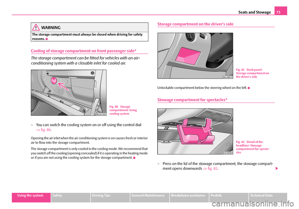
– You can switch the cooling system on or off using the control dial
⇒ fig. 80.
Opening the air inlet when the air conditioning system is on causes fresh or interior air to flow into the storage compartment.
The storage compartment is only cooled in the cooling mode. We recommend that you switch off the cooling (opening concealed) if it is operating in the heating mode or if you are not using the cooling system for the storage compartment.
Storage compartment on the driver's side
Unlockable compartment below the steering wheel on the left.
Stowage compartment for spectacles*
– Press on the lid of the stowage compartment, the stowage compart-
ment opens downwards ⇒fig. 82.
Fig. 80 Storage compartment: Using cooling system
Fig. 81 Dash panel: Storage compartment on the driver's side
Fig. 82 Detail of the headliner: Stowage compartment for specta-cles
NKO A05R 20 MR08.book Page 73 Wednesday, March 28, 2007 9:42 AM
Page 80 of 248
Heating and air conditioning system79
Using the systemSafetyDriving TipsGeneral MaintenanceBreakdown assistancePraktikTechnical Data
Set heating
Recommended settings of heating controls for:
Defrosting the windscreen and side windows
•Tu r n c o n t ro l d i a l ⇒page 78, fig. 93 to the right up to the stop,
•Blower switch in position 3,
•Turn the air distribution control into the position ,
•Open air outlet vents 4 ⇒page 80, fig. 94 and point towards the side window.
Keeping windscreen and side windows demisted
We recommend that you use the following setting in cases where the windows are misted up more than usual (e.g. when it is raining):
•Control dial where necessary to the heating range,
•Blower switch in position 2 or 3,
•Control dial to or as required or to any desired position between these symbols,
•Open air outlet vents 4 and point towards the side window.
Warming up the inside of the vehicle as rapidly as possible
•Turn control dial to the right up to the stop,
•Blower switch in position 3 or 4,
•Turn the air distribution control into the position ,
•Open the air outlet vents 4,
•We recommend that you briefly switch on the recirculated air mode with the pushbutton . The windows can steam up in this position however.
Heating the vehicle to a comfortable temperature
We recommend the following setting once the windows are no longer misted up and the desired temperature has been reached:
•Control dial at the desired heat output,
•Blower switch in position 2 or 3,
•Turn the air distribution control into the position between and ,
•Open the air outlet vents 4,
•Set the air distribution regulator as required between positions and , if the windscreen gets misted up again.
Fresh air mode - ventilation
Non pre-warmed fresh air stream s through the air inlet nozzles 3 and 4 for the following settings.
Recirculated air mode must not be switched on.
•Turn the control dial ⇒page 78, fig. 93 to the left up to the stop,
•Blower switch in the desired position,
•Turn the air distribution control into the position ,
•Open air outlet vents 3 and 4 ⇒page 80, fig. 94
The control dial can be set to other positions as required.
Recirculated air mode
In recirculated air mode air is sucked out of the interior of the vehicle
and then fed back into the interior.
Recirculated air mode prevents polluted air outside the vehicle from
getting into the vehicle, for example when driving through a tunnel or
when standing in a traffic jam.
Switching recirculated air mode on
– Press button , the button symbol lights up ⇒page 78, fig. 93.
Switching recirculated air mode off
– Press button again, the button symbol goes out.
The recirculated air mode is switched off au tomatically if the air distribution control is in position ⇒page 78, fig. 93. You can also switch recirculated air mode on again from this setting by repeatedly pressing button .
AA
AB
AC
AA
AB
AC
AA
AB
AC
A1
AA
AB
AC
AC
AA
AB
AC
AC
AC
NKO A05R 20 MR08.book Page 79 Wednesday, March 28, 2007 9:42 AM
Page 82 of 248
Heating and air conditioning system81
Using the systemSafetyDriving TipsGeneral MaintenanceBreakdown assistancePraktikTechnical Data
Air at a temperature of about 5°C may flow out of the vents under certain circum- stances when the cooling system is operating. Lengthy and uneven distribution of the air flow out of the vents (in particular at the leg area) and large differences in temperature, for example when getting out of the vehicle, can result in chills in sensitive persons.
The air inlet in front of the windscreen must be free of ice, snow or leaves in order to ensure that the heating and cooling systems operate properly.
After switching on the cooling Condensation from the evaporator of the air condi- tioning may drip down and form a puddle below the vehicle. This is quite normal and not an indication of a leak!
WARNING
•For your own safety and that of other road users, ensure that all the windows are free of ice, snow and mistin g. Please familiarize yourself about how to correctly operate th e heating and ventilation systems, how to demist and defrost the windows, as well as with the cooling mode.
•You should not leave recirculated air mode on over a longer period of time, as “stale” air may result in fatigue in the driver and occupants, divert your attention and also cause the windows to mist up. The risk of having an accident increases. Switch recirculated air mode off as soon as the windows begin misting up.
Note
•We recommend that you do not smoke in the vehicle when the recirculating air mode is operating since the smoke which is drawn at the evaporator from the inte- rior of the vehicle forms deposits in the evaporator of the air conditioning system. This produces a permanent odour when the Climatic is operating which can only be eliminated through considerable effort and expense (replacement of compressor).
Using the system
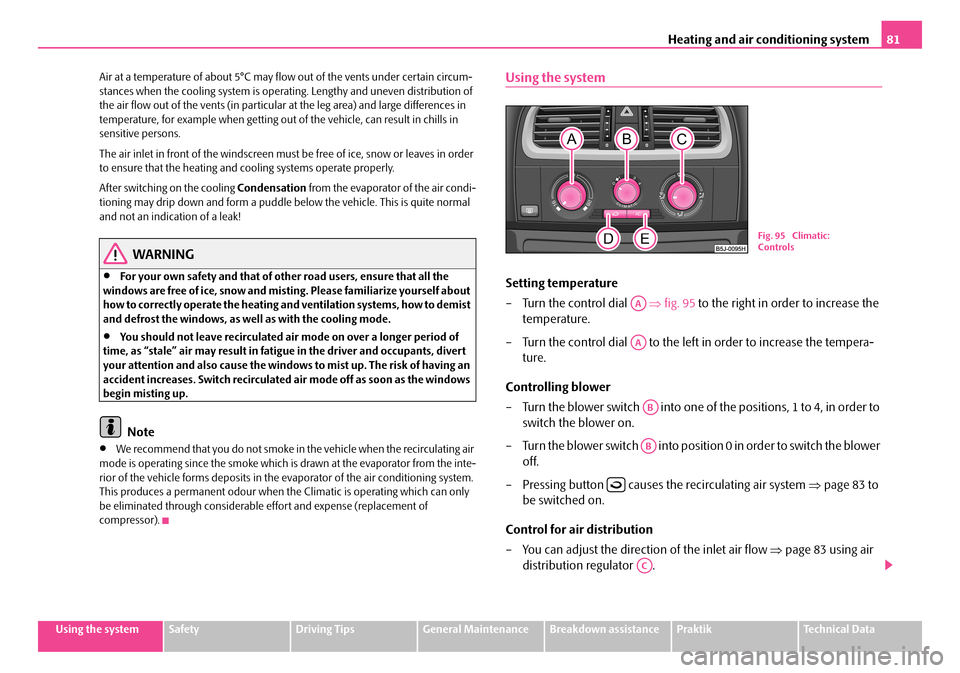
Setting temperature
– Turn the control dial ⇒fig. 95 to the right in order to increase the
temperature.
– Turn the control dial to the left in order to increase the tempera-
ture.
Controlling blower
– Turn the blower switch into one of the positions, 1 to 4, in order to
switch the blower on.
– Turn the blower switch into position 0 in order to switch the blower
off.
– Pressing button causes the recirculating air system ⇒page 83 to
be switched on.
Control for air distribution
– You can adjust the direction of the inlet air flow ⇒page 83 using air
distribution regulator .
Fig. 95 Climatic: Controls
AA
AA
AB
AB
AC
NKO A05R 20 MR08.book Page 81 Wednesday, March 28, 2007 9:42 AM
Page 83 of 248
Heating and air conditioning system82
switching cooling on and off
– Press the button . The symbol in the switch comes on.
– When you again press the switch , the cooling system is switched
off. The symbol in the button is no longer illuminated.
The set temperature will be automatically maintained other than when the control dial is on the extreme right or extreme left position:
Extreme right position - full heating.
Extreme left position - full cooling.
The controls and can be set to any desired intermediate position.
The blower should aways be on to prevent the windows from misting up.
Note
•The whole heat output will be needed to unfrost the windscreen and side windows. No warm air will be fed to the footwell. This can lead to restriction of the heating comfort.
•The used air streams out through the air removal openings in the luggage compartment.
•If the cooling system has not been switched on for a lengthy period, odours may be produced at the evaporator because of deposits. Switch the air conditioning system on at least once a month for appr oximately 5 minutes at the highest blower stage - also during the cold season of th e year - in order to remove such odours. Also open a window for a short time.
•Please refer to the information regarding recirculated air mode ⇒page 83.
•Have the air conditioning system cleaned by a specialist workshop.
Set Climatic
Recommended settings of Climatic controls for the respective operating modes:
Defrosting the windscreen and side windows
•Put the control dial ⇒page 81, fig. 95 to the temperature selected as usual by you (we recommend 22 °C)
•Blower switch in position 3 or 4
•Turn the air distribution control into the position
•Open air outlet vents 4 ⇒page 83, fig. 96 and point towards the side window.
Keeping windscreen and side windows demisted
We recommend that you use the following setting in cases where the windows are misted up more than usual (e.g. when it is raining):
•Blower switch in position 2
•Turn the air distribution control into the position between and
•Open air outlet vents 4 ⇒page 83, fig. 96 and point towards the side window.
•Switch on the cooling system by pressing button .
Warming up the inside of the vehicle as rapidly as possible
•Control dial at the desired heat temperature
•Blower switch in position 3
•Turn the air distribution control into the position
•Open the air outlet vents 4
•We recommend that you briefly switch on the recirculated air mode with the pushbutton . The windows can stea m up in this position however.
Heating the vehicle to a comfortable temperature
We recommend the following setting once the windows are no longer misted up and the desired temperature has been reached:
•Control dial at the desired heat temperature
•Blower switch in position 2
•Turn the air distribution control into the position between and
•Open the air outlet vents 4
•Set the air distribution regulator as required between positions and , if the windscreen gets misted up again.
AC
AC
AAAC
AA
AB
AC
AB
AC
AC
AA
AB
AC
AA
AB
AC
AC
NKO A05R 20 MR08.book Page 82 Wednesday, March 28, 2007 9:42 AM