ECO mode SKODA ROOMSTER 2010 1.G User Guide
[x] Cancel search | Manufacturer: SKODA, Model Year: 2010, Model line: ROOMSTER, Model: SKODA ROOMSTER 2010 1.GPages: 231, PDF Size: 12.91 MB
Page 86 of 231
Heating and air conditioning system85
Using the system
Safety
Driving Tips
General Maintenance
Breakdown assistance
Praktik
Technical Data
Recommended setting for all periods of the year:
Set the desired temperature, we recommend 22°C (72°F).
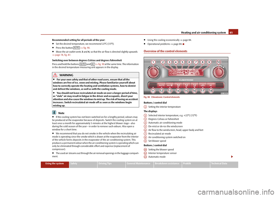
Press the button
fig. 90 .
Move the air outlet vents 3 and 4, so that the air flow is directed slightly upwards
page 78, fig. 87 .
Switching over between degrees Celsius and degrees Fahrenheit
Press and hold the buttons and fig. 90 at the same time. The information
in the desired temperature measuring unit appears in the display.
WARNING
For your own safety and that of other road users, ensure that all the
windows are free of ice, snow and mistin g. Please familiarize yourself about
how to correctly operate th e heating and ventilation systems, how to demist
and defrost the windows, as well as with the cooling mode.
You should not leave recirculated air mode on over a longer period of time,
as “stale” air may result in fatigue in the driver and occupants, divert your
attention and also cause the windows to mist up. The risk of having an accident
increases. Switch recirculated air mode off as soon as the windows begin
misting up.Note
If the cooling system has not been switched on for a lengthy period, odours may
be produced at the evaporator because of deposits. Switch the cooling system on at
least once a month for approximately 5 minut es at the highest blower stage - also
during the cold season of the year - in order to remove such odours. Also open a
window for a short time.
We recommend that you do not smoke in the vehicle when the recirculating air
mode is operating since the smoke which is drawn at the evaporator from the interior
of the vehicle forms deposits in the evapor ator of the air conditioning system. This
produces a permanent odour when the air co nditioning system is operating which can
only be eliminated through considerable effort and expense (replacement of
compressor).
The used air streams out through the air removal openings in the luggage compart-
ment.
Using the cooling economically page 84.
Operational problems page 84.
Overview of the control elementsFig. 90 Climatronic: Control elementsButtons / control dial
Setting the interior temperature
The displays Selected interior temperature, e.g. +22°C (72°F)
Degrees Celsius or Fahrenheit
Automatic air conditioning mode
De-mist or de-ice the windscreen
Air flow to the windscreen, head, upper body and feet
Recirculated air mode
Air conditioning sy stem switched on
Set blower speed
Buttons / control dial Setting the blower speed
Interior temperature sensor
Automatic mode
AUTO
AUTO
AC
A1A2A3A4A5A6A7A8A9A10A11A12
s16g.4.book Page 85 Wednesda y, February 10, 2010 3:53 PM
Page 91 of 231
Starting-off and Driving
90
switch on again after some time if the co olant temperature rises because of an accu-
mulation of heat in the engine or if the engine is warm and the engine compartment is
additionally heated by strong sunlight.
This is why particular care is required when carrying out any work in the engine
compartment page 162, “Working in the engine compartment”.
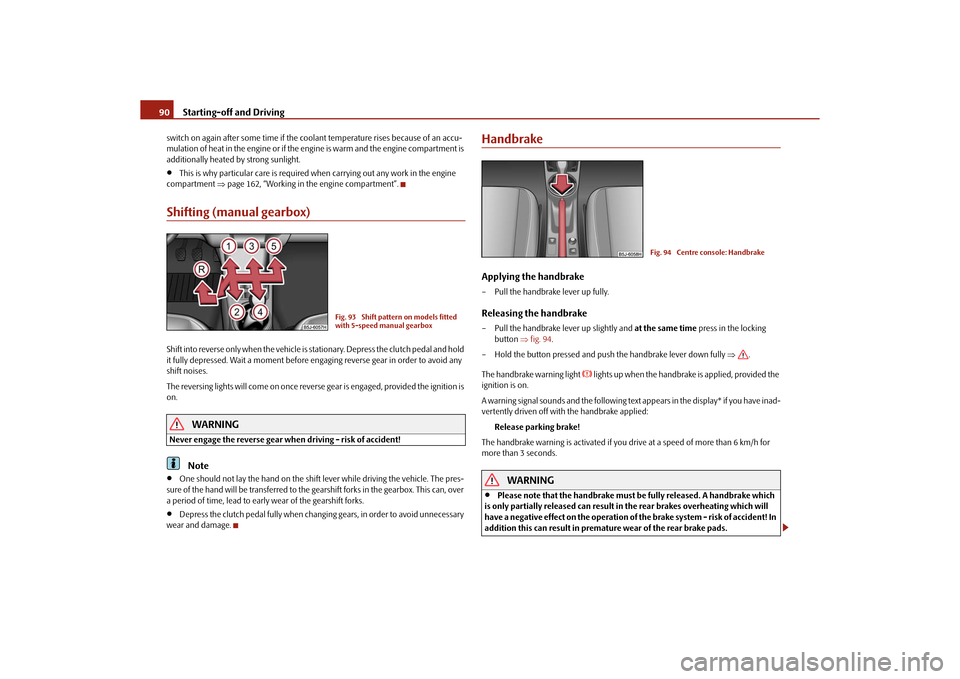
Shifting (manual gearbox)Shift into reverse only when the vehicle is stationary. Depress the clutch pedal and hold
it fully depressed. Wait a moment before en gaging reverse gear in order to avoid any
shift noises.
The reversing lights will come on once reverse gear is engaged, provided the ignition is
on.
WARNING
Never engage the reverse gear when driving - risk of accident!
Note
One should not lay the hand on the shift lever while driving the vehicle. The pres-
sure of the hand will be transferred to the gearshift forks in the gearbox. This can, over
a period of time, lead to early wear of the gearshift forks.
Depress the clutch pedal fully when changi ng gears, in order to avoid unnecessary
wear and damage.
HandbrakeApplying the handbrake– Pull the handbrake lever up fully.Releasing the handbrake– Pull the handbrake lever up slightly and at the same time press in the locking
button fig. 94 .
– Hold the button pressed and push the handbrake lever down fully .
The handbrake warning light
lights up when the handbrak e is applied, provided the
ignition is on.
A warning signal sounds and the following text appears in the display* if you have inad-
vertently driven off with the handbrake applied:
Release parking brake!
The handbrake warning is activated if you drive at a speed of more than 6 km/h for
more than 3 seconds.
WARNING
Please note that the handbrake must be fully released. A handbrake which
is only partially released can result in the rear brakes overheating which will
have a negative effect on the operation of the brake system - risk of accident! In
addition this can result in premature wear of the rear brake pads.
Fig. 93 Shift pattern on models fitted
with 5-speed manual gearbox
Fig. 94 Centre console: Handbrake
s16g.4.book Page 90 Wednesda y, February 10, 2010 3:53 PM
Page 92 of 231
Starting-off and Driving91
Using the system
Safety
Driving Tips
General Maintenance
Breakdown assistance
Praktik
Technical Data
Never leave children unattended in the vehicle. The children might, for
example, release the handbrake or take the vehicle out of gear. The vehicle
might then move off - risk of accident!Caution
After the car has come to a stop, always firs t of all apply the handbrake firmly before
then additionally engaging a gear (manual gearbox) or moving the selector lever into
position P (automatic gearbox).Parking aid*The parking aid provides a warning of obstacles behind the vehicle.The audible parking aid determines the di stance between the rear bumper and an
obstacle located behind the vehicle with the aid of ultrasound sensors. The sensors are
integrated in the rear bumper.
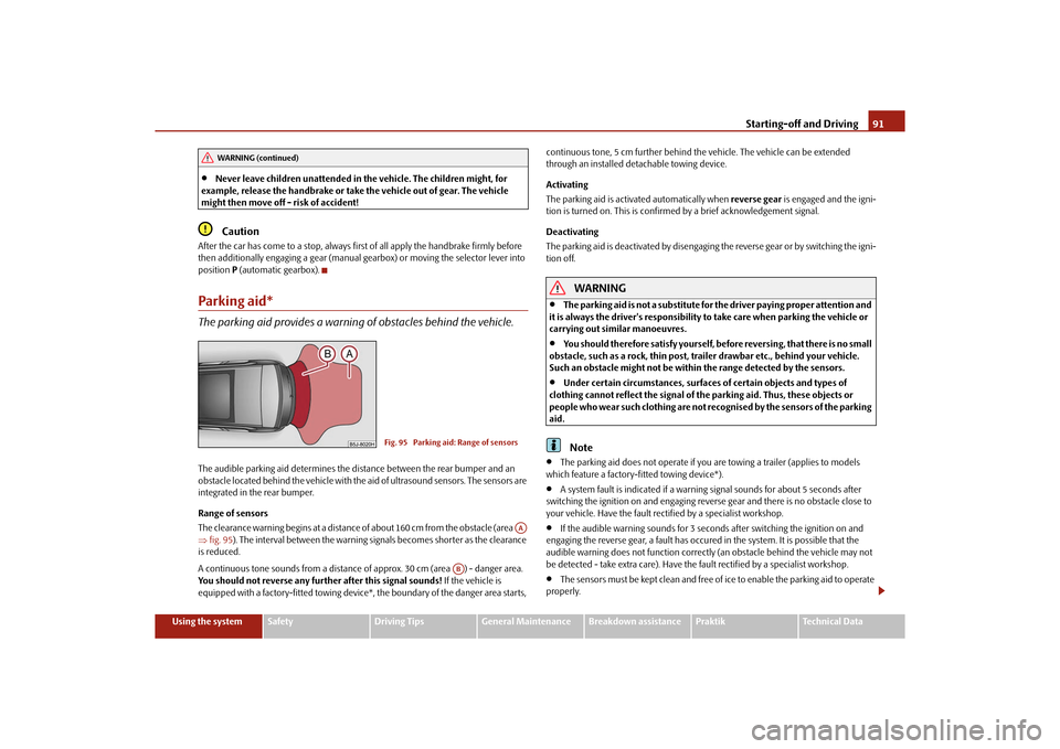
Range of sensors
The clearance warning begins at a distance of about 160 cm from the obstacle (area
fig. 95 ). The interval between the warning signals becomes shorter as the clearance
is reduced.
A continuous tone sounds from a distance of approx. 30 cm (area ) - danger area.
You should not reverse any further after this signal sounds! If the vehicle is
equipped with a factory-fitted towing device*, the boundary of the danger area starts, continuous tone, 5 cm furt
her behind the vehicle. The vehicle can be extended
through an installed deta chable towing device.
Activating
The parking aid is activated automatically when reverse gear is engaged and the igni-
tion is turned on. This is confirmed by a brief acknowledgement signal.
Deactivating
The parking aid is deactivated by disengaging the reverse gear or by switching the igni-
tion off.
WARNING
The parking aid is not a substitute for the driver paying proper attention and
it is always the driver's responsibility to take care when parking the vehicle or
carrying out similar manoeuvres.
You should therefore satisfy yourself, before reversing, that there is no small
obstacle, such as a rock, thin post, trailer drawbar etc., behind your vehicle.
Such an obstacle might not be within the range detected by the sensors.
Under certain circumstances, surfaces of certain objects and types of
clothing cannot reflect the signal of the parking aid. Thus, these objects or
people who wear such clothing are not recognised by the sensors of the parking
aid.Note
The parking aid does not operate if you are towing a trailer (applies to models
which feature a factory-fitted towing device*).
A system fault is indicated if a warning signal sounds for about 5 seconds after
switching the ignition on and engaging reverse gear and there is no obstacle close to
your vehicle. Have the fault rectified by a specialist workshop.
If the audible warning sounds for 3 seconds after switching the ignition on and
engaging the reverse gear, a fault has occured in the system. It is possible that the
audible warning does not function correctl y (an obstacle behind the vehicle may not
be detected - take extra care). Have the fault rectified by a specialist workshop.
The sensors must be kept clean and free of ice to enable the parking aid to operate
properly.
WARNING (continued)
Fig. 95 Parking aid: Range of sensors
AA
AB
s16g.4.book Page 91 Wednesda y, February 10, 2010 3:53 PM
Page 95 of 231
Automatic gearbox
94
Automatic gearboxAutomatic gearbox*Information for driving with the 6-speed automatic gearbox*
Your car is equipped with a conv entional 6-speed automatic gearbox.The maximum speed is reached in the 5th gear. The 6th gear serves as an economic
driving programme, which is intended to redu ce the fuel consumption. Shifting up and
down through the gears is performed automa tically. You can also, however, switch the
gearbox over into the Tiptronic mode. This mode makes it possible for you to also shift
gears manually page 98.Starting-off and Driving– Depress the brake pedal fully and keep it depressed.
– Press the Shiftlock button (button in ha ndle of the selector lever), move the
selector lever into the desired position, e.g. D page 95, and then release the
Shiftlock button.
– Wait a moment until the gearbox has shif ted (a slight engagement nudge can be
felt).
– Release the brake pedal and depress the accelerator .Stop– The selector lever position N does not have to be selected when stopping just for
a short time, such as at a cross roads. It is sufficient to hold the vehicle stationary
using the foot brake. The engine can, however, be allowed just to idle.Parking– Depress the brake pedal and hold it depressed.
– Apply the handbrake firmly.
– Press and Shiftlock button in the selector lever, move the selector lever to P and
then release the Shiftlock button.
The engine can only be started when the selector lever is in position P or N page 88. It is sufficient to engage selector lever position
P when parking on a flat surface. When
parking on a slope you should first apply the handbrake firmly and then move the
selector lever into position P. This is to ensure that there is no excessive pressure acting
on the lock mechanism and that it is easier to subsequently move the selector lever out
of position P.
If the selector lever position N is selected by accident while driving it is first necessary
to release pressure on the accelerator pedal and wait for idling speed of the engine to
be reached before engaging a drive position in the selector lever.
WARNING
Do not depress the accelerator when changing the position of the selector
lever if the car is stationary and the engine is running - risk of accident!
Never move the selector lever into position R or P when driving - risk of an
accident!
When the engine is running and the vehi cle is stationary, it is necessary to
hold the car with the brake pedal in all the positions of the selector lever (except
P and N) since the power transmission is never completely interrupted, also not
when the engine is idling - the vehicle creeps.
Information for driving with the automatic gearbox DSG*
The abbreviation DSG mean s Direct shift gearbox (Direct shift gearbox).Two independent clutches are needed for the power transmission between the engine
and the gearbox. These replace the torque converter of the conventional automatic
gearbox. Their shifting is matched in such a way that there are no jerks when shifting
the gear and the power transmission of the engine to the front wheels is not inter-
rupted. Shifting up and down through the gears is performed automatically. You can
also, however, switch the gearbox over into the Tiptronic mode. This mode makes it
possible for you to also shift gears manually page 98.Starting-off and Driving– Depress the brake pedal fully and keep it depressed.
s16g.4.book Page 94 Wednesda y, February 10, 2010 3:53 PM
Page 98 of 231
Automatic gearbox97
Using the system
Safety
Driving Tips
General Maintenance
Breakdown assistance
Praktik
Technical Data
A time delay element ensures that the selector lever is not blocked when rapidly
switching over the position
N (e.g. from R to D). This does, for example, allow one to
seesaw out a stuck vehicle. The selector lever lo ck will click into place if the lever is in
the N position for more than 2 seconds without the brake pedal being pressed.
The selector lever lock is only active if the vehicle is stationary or moving at speed of
less than 5 km/hour. The lock is swit ched off automatically into position N when the
car is travelling at a higher speed.
Shiftlock button
The Shiftlock button in the hand le of selector lever prevents certain selector lever posi-
tions being engaged inadvertently. The selector lever lock is cancelled when you press
the Shiftlock button.
Keylock - Ignition key withdrawal lock
You can only withdraw the ignition key after switching off the ignition if the selector
lever is in position P. If the ignition key is withdrawn, the selector lever is blocked in
position P.
Kickdown function
The kickdown function provides you with maximum acceleration
power.Fully depressing the accelerator pedal allows the kickdown function to be activated in
the desired driving program. This function has precedence over the driving
programme and serves for maximum acceleration of the vehicle when exploiting the
maximum power potential of the engine wi thout taking into account the current
selector lever position ( D, S or Tiptronic ). The gearbox shifts down to one or several
gears in line with the driving state and the vehicle accelerates. The gearbox does not
shift up into the highest gear until the engine has reached its maximum revolutions for
this gear range.
WARNING
Please note that using the kickdown function can result in the driven wheels
spinning on a smooth or slippery road surface - risk of skidding!
Dynamic shift programmeThe automatic gearbox of your vehicle is controlled electronically. Shifting up and
down through the gears is performed automatically on the basis of pre-defined driving
programmes.
Adopting a moderate style of driving will cause the gearbox to select the most
economical driving programme. Shifting up into a higher gear as soon as possible and
shifting down as late as po ssible will have a favourable effect on your fuel consump-
tion.
Adopting a sporty style of driving with rapid movements of the accelerator pedal
combined with sharp acceleration and freque nt changes in speed, exploiting the top
speed of the car or depressing the accelerator pedal (kickdown function), will cause
the gearbox to switch over to this style of driving and shift down earlier with frequent
changes in gears in comparison to the moderate style of driving.
Selecting the most appropriate driving programme for the particular style of driving is
a continuous process. Irrespective of this it is, however, possible to switch or shift down
into a dynamic shift programme by depressi ng the accelerator rapidly. The gearbox
shifts down into a lower gear matching the speed of the car and this allows you to
accelerate rapidly (e.g. when overtaking) without having to depress the accelerator
pedal fully into the kickdown range. The or iginal programme will be reactivated to
match your particular styl e of driving once the gearbox has shifted up again.
When driving in hilly regions, the gears are selected to match uphill and downhill
sections. This avoids the gearbox frequently shifting up and down when negotiating an
uphill stretch. When driving downhill, it is possible to shift down into the Tiptronic
position, in order to exploit the engine brake torque.
s16g.4.book Page 97 Wednesda y, February 10, 2010 3:53 PM
Page 102 of 231
Communication101
Using the system
Safety
Driving Tips
General Maintenance
Breakdown assistance
Praktik
Technical Data
The buttons apply for the respective operating mode of the current radio or navigation
system.
Note
The loudspeakers in the vehicle are matched to a power output of the radio and
navigation system of 4x 20°W.
For the equipment sound system*, the loudspeakers are matched to a power
output of the amplifier of 4x40°W + 6x20 W.
Mobile phones and tw o-way radio systemsThe installation of a mobile phone and two-way radio system in a vehicle should be
carried out by a specialist garage.
Mobile phones send and receive radio waves during a conversation as well as in
standby mode. Radio waves can be harmful to the human body if their frequency
exceeds certain limit values.
Škoda Auto permits the operation of mobile phones and two-way radio systems with
a professionally installed external aerial and a maximum transmission power of up to
10 watts.
It is essential that you inform a specialist garage about the possibilites to assemble and
operate mobile phones and two-way radio sets which have a power output of more
than 10 W. They will inform you which technical possibilities exist for retrofitting
mobile phones.
When using a mobille phone inside the vehicl e, which is not inserted into the phone
adapter, and thus has no connection to the external aerial, the electromagnetic radia-
tion can exceed the current limit value. We therefore recommend to operate a mobile
phone in the vehicle only when it is conne cted to an external aerial via the phone
adapter. This improves the quality of the connection.
Operation of mobile phones or two-way ra dio systems may interfere with functioning
of the electronic systems of your vehicle. The reasons for this may be:
no external aerial,
external aerial incorrectly installed,
transmission power gr eater than 10 watts.
WARNING
If a mobile phone or a two-way radio system is operated in the vehicle
without using a special external aerial or an external aerial which has been
incorrectly installed, this can increase the strength of the electromagnetic field
in the interior of the vehicle.
Please concentrate fully at all times on your driving!
You must not install two-way radio systems, mobile phones or mounts on
the covers of the airbags or within the immediate deployment range of airbags.
This might result in injuries to the occupants in the event of an accident.
Never leave a mobile phone on a seat, on the dash panel or in another area,
from which it can be thrown during a sudden braking manoeuver, an accident
or a collision. In this case, the occupants of the vehicle might be injured.Note
Observe the country-specific regulations for the use of mobile phones in vehicles.Universal telephone preinstallation GSM II*IntroductionThe universal telephone preinstallation GSM II is a built-in “handsfree-system”, it
provides a voice operated convenience mode via the multifunction steering wheel* or
the navigation system*.
All communication between a telephone and the handsfree-system of your vehicle
can only be established with the help of the Bluetooth
® technology. The adapter*
serves only for charging the telephone and fo r transmitting the signal to the external
aerial of the vehicle.
a)On vehicles which are equipped with the universal telephone prei nstallation GSM II, pressing the button only allows to operate the telephone.
A1
s16g.4.book Page 101 Wednesday, February 10, 2010 3:53 PM
Page 135 of 231
Intelligent Technology
134
Changes to vehicle (e.g. on engine, on th e brakes, on chassis or another combina-
tion of tyres and wheels) can influence the function of the ESP page 179, “Accesso-
ries, changes and replacement of parts”.
Traction control system (TCS)*
The traction control system prevents the driven wheels from spinning
when accelerating.General
The TCS makes it much easier, and sometimes at all possible, to start off, accelerate and
climb a steep hill when the conditions of the road surface are unfavourable.
Operating principle
The TCS switches on automatically when th e engine is started and then conducts a
self-test. The system monitors the speeds of the driven wheels with the aid of the ABS
sensors. If the wheels are spinning, the force transmitted to the road surface is auto-
matically adapted by reducing the engine speed. The system operates at all speeds.
The TCS operates in combination with the ABS page 136, “Antilock brake system
(ABS)”. The TCS will not function if a fault exists in the ABS system.
Switching off
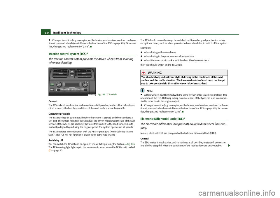
You can switch the TCS off and on again as you wish by pressing the button fig. 126 .
The TCS warning light lights up in the instru ment cluster when the TCS is switched off page 30. The TCS should normally always
be switched on. It may be good practice in certain
exceptional cases, such as when you wish to have wheel slip, to switch off the system.
Examples:
when driving with snow chains;
when driving in deep snow or on a loose surface;
when it is necessary to rock a vehicle when it has become stuck.
then you should switch on the TCS again.
WARNING
You should always adjust your style of driving to the conditions of the road
surface and the traffic situation. The increased safety offered must not tempt
you to take greater risks than otherwise - risk of an accident!
Note
All four wheels must be fitted with the same tyres in order to achieve problem-free
operation of the TCS. Differing rolling circum ferences of the tyres can lead to an unde-
sirable reduction in the engine output.
Changes to vehicle (e.g. on engine, on the brakes, on chassis or another combina-
tion of tyres and wheels) can influence the function of the TCS page 179, “Accesso-
ries, changes and replacement of parts”.
Electronic Differential Lock (EDL)*
The electronic differential lock prev ents an individual wheel from slip-
ping.Models fitted with ESP are equipped with electronic differential lock (EDL).
General
The EDL makes it much easier, and sometimes at all possible, to st art off, accelerate
and climb a steep hill when the conditions of the road surface are unfavourable.
Fig. 126 TCS switch
s16g.4.book Page 134 Wednesda y, February 10, 2010 3:53 PM
Page 148 of 231
Driving and the Environment147
Using the system
Safety
Driving Tips
General Maintenance
Breakdown assistance
Praktik
Technical Data
This particularly applies to
models with a lowered suspen sion (sport suspension) and
also when your vehicle is fully laden.
Driving through bodies of water on roadsIn order to avoid damage to the vehicle, for example when driving through flooded
roads, observe the following:
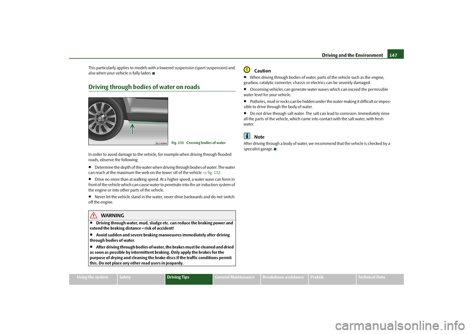
Determine the depth of the water when driv ing through bodies of water. The water
can reach at the maximum the web on the lower sill of the vehicle fig. 132 .
Drive no more than at walking speed. At a higher speed, a water wave can form in
front of the vehicle which can cause water to penetrate into the air induction system of
the engine or into other parts of the vehicle.
Never let the vehicle stand in the water, never drive backwards and do not switch
off the engine.
WARNING
Driving through water, mud, sludge etc. can reduce the braking power and
extend the braking distance - risk of accident!
Avoid sudden and severe braking manoeuvres immediately after driving
through bodies of water.
After driving through bodies of water, the brakes must be cleaned and dried
as soon as possible by intermittent braking. Only apply the brakes for the
purpose of drying and cleaning the brake discs if the traffic conditions permit
this. Do not place any other road users in jeopardy.
Caution
When driving through bodies of water, pa rts of the vehicle such as the engine,
gearbox, catalytic converter, chassis or electrics can be severely damaged.
Oncoming vehicles can generate water waves which ca n exceed the permissible
water level for your vehicle.
Potholes, mud or rocks can be hidden under the water making it difficult or impos-
sible to drive through the body of water.
Do not drive through salt water. The salt can lead to corrosion. Immediately rinse
all the parts of the vehicle, which came into contact with the salt water, with fresh
water.Note
After driving through a body of water, we recommend that the vehicle is checked by a
specialist garage.
Fig. 132 Crossing bodies of water
s16g.4.book Page 147 Wednesda y, February 10, 2010 3:53 PM
Page 177 of 231
Wheels and Tyres
176
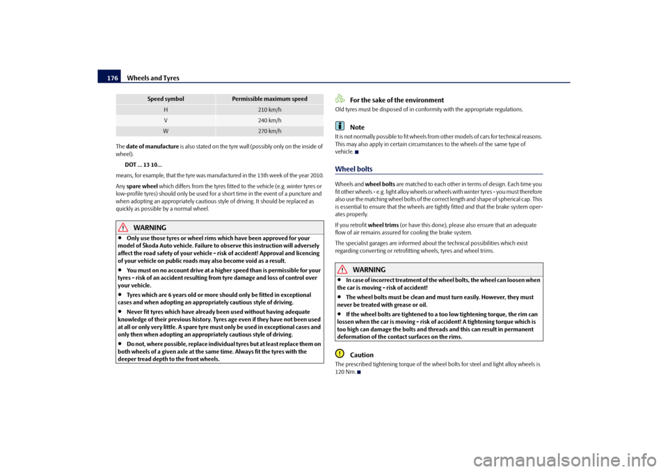
The date of manufacture is also stated on the tyre wall (possibly only on the inside of
wheel).
DOT ... 13 10...
means, for example, that the tyre was ma nufactured in the 13th week of the year 2010.
Any spare wheel which differs from the tyres fitted to the vehicle (e.g. winter tyres or
low-profile tyres) should only be used for a short time in the event of a puncture and
when adopting an appropriately cautious styl e of driving. It should be replaced as
quickly as possible by a normal wheel.
WARNING
Only use those tyres or wheel rims which have been approved for your
model of Škoda Auto vehicle. Failure to observe this instruction will adversely
affect the road safety of your vehicle - risk of accident! Approval and licencing
of your vehicle on public roads ma y also become void as a result.
You must on no account drive at a high er speed than is permissible for your
tyres - risk of an accident resulting from tyre damage and loss of control over
your vehicle.
Tyres which are 6 years old or more should only be fitted in exceptional
cases and when adopting an approp riately cautious style of driving.
Never fit tyres which have already been used without having adequate
knowledge of their previous history. Tyre s age even if they have not been used
at all or only very little. A spare tyre must only be used in exceptional cases and
only then when adopting an appropriately cautious style of driving.
Do not, where possible, replace individu al tyres but at least replace them on
both wheels of a given axle at the same time. Always fit the tyres with the
deeper tread depth to the front wheels.
For the sake of the environment
Old tyres must be disposed of in conformity with the appropriate regulations.
Note
It is not normally possible to fit wheels from other models of cars for technical reasons.
This may also apply in certain circumstance s to the wheels of the same type of
vehicle.Wheel boltsWheels and wheel bolts are matched to each other in terms of design. Each time you
fit other wheels - e.g. light alloy wheels or wheels with winter tyres - you must therefore
also use the matching wheel bolts of the corr ect length and shape of spherical cap. This
is essential to ensure that the wheels are tightly fitted and that the brake system oper-
ates properly.
If you retrofit wheel trims (or have this done), please also ensure that an adequate
flow of air remains assured for cooling the brake system.
The specialist garages are informed about the technical possibilities which exist
regarding converting or retrofitting wheels, tyres and wheel trims.
WARNING
In case of incorrect treatment of the wheel bolts, the wheel can loosen when
the car is moving - risk of accident!
The wheel bolts must be clean and must turn easily. However, they must
never be treated with grease or oil.
If the wheel bolts are tightened to a too low tightening torque, the rim can
lossen when the car is moving - risk of accident! A tightening torque which is
too high can damage the bolts and threads and this can result in permanent
deformation of the contact surfaces on the rims.Caution
The prescribed tightening torque of the wheel bolts for steel and light alloy wheels is
120 Nm.
H
210 km/h
V
240 km/h
W
270 km/h
Speed symbol
Permissible maximum speed
s16g.4.book Page 176 Wednesda y, February 10, 2010 3:53 PM
Page 195 of 231
Fuses and light bulbs
194
– Release the fixtures in the openings using a flat screwdriver and fold the cover
upwards in direction of arrow .
– Find out which fuse belongs to th e component which is not operating.
– Defect fuses can be detected by their melted metal strips. Replace the defect fuse by a new fuse of the same ampere number.
Caution
Never attempt to “repair” fuses and also do not replace them with a fuse of a higher
amperage - risk of fire! This may also cause damage at an other part of the electrical
system.
Have the electrical system checked as quickl y as possible by a specialist garage if a
newly inserted fuse blows again after a short time.Note
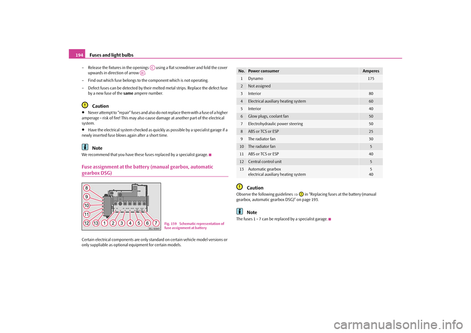
We recommend that you have these fuses replaced by a specialist garage.Fuse assignment at the battery (manual gearbox, automatic gearbox DSG)Certain electrical components are only standard on certain vehicle model versions or
only suppliable as optional equipment for certain models.
Caution
Observe the following guidelines in “Replacing fuses at the battery (manual
gearbox, automatic gearbox DSG)” on page 193.
Note
The fuses 1 - 7 can be replac ed by a specialist garage.
AC
AD
Fig. 159 Schematic representation of
fuse assignment at battery
No.
Power consumer
Amperes
1
Dynamo
175
2
Not assigned
3
Interior
80
4
Electrical auxiliary heating system
60
5
Interior
40
6
Glow plugs, coolant fan
50
7
Electrohydraulic power steering
50
8
ABS or TCS or ESP
25
9
The radiator fan
30
10
The radiator fan
5
11
ABS or TCS or ESP
40
12
Central control unit
5
13
Automatic gearbox
electrical auxiliary heating system
5
40
s16g.4.book Page 194 Wednesda y, February 10, 2010 3:53 PM