navigation system SKODA ROOMSTER 2010 1.G Owner's Manual
[x] Cancel search | Manufacturer: SKODA, Model Year: 2010, Model line: ROOMSTER, Model: SKODA ROOMSTER 2010 1.GPages: 231, PDF Size: 12.91 MB
Page 10 of 231
Cockpit9
Using the system
Safety
Driving Tips
General Maintenance
Breakdown assistance
Praktik
Technical Data
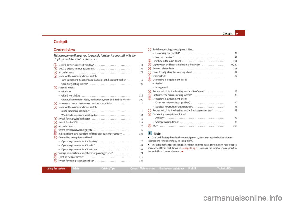
CockpitGeneral viewThis overview will help you to quickly familiarise yourself with the
displays and the control elements.
Electric power-operated window* . . . . . . . . . . . . . . . . . . . . . . . . . . . . . . .
Electric exterior mirror adjustment* . . . . . . . . . . . . . . . . . . . . . . . . . . . . .
Air outlet vents . . . . . . . . . . . . . . . . . . . . . . . . . . . . . . . . . . . . . . . . . . . . . . . .
Lever for the multi-functional switch:
Turn signal light, headlight and parking light, headlight flasher . .
Speed regulating system* . . . . . . . . . . . . . . . . . . . . . . . . . . . . . . . . . . . .
Steering wheel:
with horn
with driver airbag . . . . . . . . . . . . . . . . . . . . . . . . . . . . . . . . . . . . . . . . . . .
with pushbuttons for radio, navi gation system and mobile phone*
Instrument cluster: Instruments and indicator lights . . . . . . . . . . . . . .
Lever for the multi-functional switch:
Multi-functional indicator* . . . . . . . . . . . . . . . . . . . . . . . . . . . . . . . . . . .
Windshield wiper and wash system . . . . . . . . . . . . . . . . . . . . . . . . . . .
Switch for rear window heater . . . . . . . . . . . . . . . . . . . . . . . . . . . . . . . . . .
Switch for the TCS* . . . . . . . . . . . . . . . . . . . . . . . . . . . . . . . . . . . . . . . . . . . . .
Air outlet vents . . . . . . . . . . . . . . . . . . . . . . . . . . . . . . . . . . . . . . . . . . . . . . . .
Switch for hazard warning lights . . . . . . . . . . . . . . . . . . . . . . . . . . . . . . . . .
Indicator light for a switched off front seat passenger airbag* . . . . . .
Depending on equipment fitted:
Operating controls for the heating . . . . . . . . . . . . . . . . . . . . . . . . . . . .
Operating controls for Climatic* . . . . . . . . . . . . . . . . . . . . . . . . . . . . . .
Operating controls for Climatronic* . . . . . . . . . . . . . . . . . . . . . . . . . . .
Storage compartments on the front passenger side* . . . . . . . . . . . . . .
Front passenger airbag* . . . . . . . . . . . . . . . . . . . . . . . . . . . . . . . . . . . . . . . .
Switch for front passenger airbag* . . . . . . . . . . . . . . . . . . . . . . . . . . . . . . . Switch depending on equipment fitted:
Unlocking the boot lid* . . . . . . . . . . . . . . . . . . . . . . . . . . . . . . . . . . . . . .
Interior monitor* . . . . . . . . . . . . . . . . . . . . . . . . . . . . . . . . . . . . . . . . . . . .
Fuse box in the dash panel . . . . . . . . . . . . . . . . . . . . . . . . . . . . . . . . . . . . . .
Light switch and headlamp beam adjustment . . . . . . . . . . . . . . . . . . . .
Bonnet release lever . . . . . . . . . . . . . . . . . . . . . . . . . . . . . . . . . . . . . . . . . . . .
Lever for adjusting the steering wheel . . . . . . . . . . . . . . . . . . . . . . . . . . . .
Ignition lock . . . . . . . . . . . . . . . . . . . . . . . . . . . . . . . . . . . . . . . . . . . . . . . . . . .
Depending on equipment fitted:
Radio*
Navigation*
Rocker switch for the heating on the driver's seat* . . . . . . . . . . . . . . . .
Button for the central locking system* . . . . . . . . . . . . . . . . . . . . . . . . . . .
Depending on equipment fitted:
Gearshift lever (manual gearbox) . . . . . . . . . . . . . . . . . . . . . . . . . . . . . .
Selector lever (automatic gearbox*) . . . . . . . . . . . . . . . . . . . . . . . . . . .
Rocker switch for the heating on the front passenger seat* . . . . . . . .
Depending on equipment fitted:
Ashtray* . . . . . . . . . . . . . . . . . . . . . . . . . . . . . . . . . . . . . . . . . . . . . . . . . . . .
Storage compartment . . . . . . . . . . . . . . . . . . . . . . . . . . . . . . . . . . . . . . . .
MDI* . . . . . . . . . . . . . . . . . . . . . . . . . . . . . . . . . . . . . . . . . . . . . . . . . . . . . . . . . .
Note
Cars with factory-fitted radio or naviga tion system are supplied with separate
instructions for operating such equipment.
The arrangement of the control elements on right-hand drive models may differ to
some extent from that shown in page 8, fig. 1. However the symbols correspond to
the individual control elements.
A1
43
A2
55
A3
78
A4
5092
A5
119100
A6
15
A7
1853
A8
52
A9
133
A10
78
A11
49
A12
125
A13
788184
A14
74
A15
119
A16
125
A17
3942
A18
191
A19
46, 49
A20
161
A21
87
A22
87
A23A24
59
A25
38
A26
9095
A27
59
A28
7275
A29
107
s16g.4.book Page 9 Wednesda y, February 10, 2010 3:53 PM
Page 23 of 231
Instruments and warning lights
22
An audible signal sounds as an additional warning signal.
The set speed limit remains stored even after switching off the ignition.MAXI DOT display (information display)*IntroductionThe information display provides you with information in a convenient way
concerning the current operating state of your vehicle . The information system also
provides you with data (depending on the equipment installed in the vehicle) relating
to the radio, mobile phone, multi-function al indicator, navigation system, the unit
connected to the MDI input and the automatic gearbox.
Certain functions and operating conditions are always being checked on the vehicle
when the ignition is switched on and also while driving.
Functional faults, if required repair work and other information are indicated by red
symbols page 23 and yellow symbols page 24.
Lighting up of certain symbols is combined with an acoustic warning signal.
Information and texts giving warnings are also shown in the display page 25.
The display of text is possible in the following languages: Czech, English, German, French, Italian, Spanish, Portuguese, Russian and Chinese.
You can select the desired language in the setting menu.
The following information can be shown in the display (depending on the equipment
installed on the vehicle):
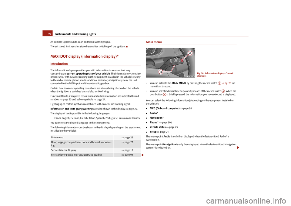
Main menu– You can activate the MAIN MENU by pressing the rocker switch fig. 20 for
more than 1 second.
– You can select indi vidual menu points by means of the rocker switch . When the
pushbutton is briefly pressed, the info rmation you have selected is displayed.
You can select the following information (depending on the equipment installed on
the vehicle):
MFD (Onboard computer) page 18
Audio *
Navigation *
Phone* page 101
Vehicle status page 23
Setup page 24
The menu point Audio is only then displayed when the factory-fitted Radio* is
switched on.
The menu point Navigation is only then displayed when the factory-fitted Navigation
system* is switched on.
Main menu
page 22
Door, luggage compartment door and bonnet ajar warn-
ing
page 23
Service Interval Display
page 17
Selector lever position for an automatic gearbox
page 94
Fig. 20 Information display: Control
elements
AAAA
AB
s16g.4.book Page 22 Wednesda y, February 10, 2010 3:53 PM
Page 24 of 231
Instruments and warning lights23
Using the system
Safety
Driving Tips
General Maintenance
Breakdown assistance
Praktik
Technical Data
Note
If warning messages are shown in the information display page 23, these
messages can be confirmed with the button on the windshield wiper lever in order
to call up the main menu.
If you do not activate the information display at that moment, the menu shifts to
one level higher every 10 seconds.
The operation of the factory-fitted radio* or the navigation system* is described in
separate operating instructions to be found in the on-board literature.
Door, luggage compartment door and bonnet ajar warningThe door, luggage compartment and bonnet ajar warning lights up if at least one door,
the luggage compartment or bonnet are not closed. The symbol indicates which door
is still open or whether the luggage compartment door or bonnet is not closed.
The symbol goes out as soon as the doors, luggage compartment door and bonnet are
completely closed.
A warning signal sounds if the car is driven at a speed of more than 6km/hour and if
the engine or the luggage compartment door is open.Auto Check ControlCar stateThe Auto Check Control carries out a chec k of certain functions and vehicle compo-
nents. The check is performed constantly when the ignition is switched on, both when
the vehicle is stationary, as well as when driving.
Some operational faults, urgent repairs, service work or other information appear in
the display of the instrument cluster. The di splays are shown with a red or yellow light
symbol depending on the priority of the message.
The red symbols indicate danger (priority 1) while the yellow symbols indicate a
warning (priortity 2). Information for the driver may also appear in addition to the
symbols page 25. Shown in the menu
Vehicle status, if there is at least one error message. After selecting
this menu the first of the error messages is displayed. Several error messages are
shown on the display under the message e.g. 1/3 . This indicates that the first of a total
of three error messages is displayed. The respective messages are displayed one after
the other in an interval of 5 seconds. Check as soon as possible the displayed error
messages.
As long as the operational faults are not rectified, the symbols are always indicated
again. After the first display, the symbol s are indicated without information for the
driver.
If a fault occurs, a warning signal will also so und in addition to the symbol and text in
the display:
Priority 1 - three warning signals
Priority 2 - one warning signal
Red symbols
A red symbol signals danger.– Bring the vehicle to a stop.
– Switch the engine off.
– Investigate the function indicated.
– Obtain professional assistance.
Meaning of the red symbols:
Three successive warning signals will sound if a red symbol appears.
AB
Engine oil pressure too low
page 28
Overheated clutches of the automatic gear-
box DSG*
page 94
s16g.4.book Page 23 Wednesda y, February 10, 2010 3:53 PM
Page 101 of 231
Communication
100
CommunicationMultifunction steering wheel*Operate radio und navigation on the multifunction steering wheel
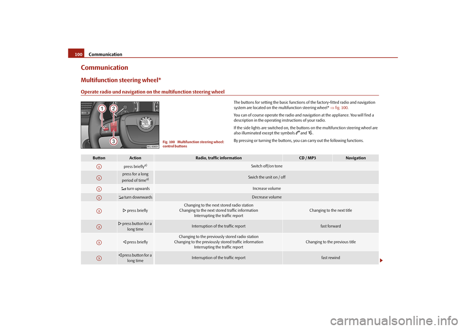
The buttons for setting the basic functions of the factory-fitted radio and navigation
system are located on the multifunction steering wheel* fig. 100 .
You can of course operate the radio and navi gation at the appliance. You will find a
description in the operating instructions of your radio.
If the side lights are switched on, the buttons on the multifunction steering wheel are
also illuminated except the symbols
and
.
By pressing or turning the buttons, yo u can carry out the following functions.
Fig. 100 Multifunction steering wheel:
control buttons
Button
Action
Radio, traffic information
CD / MP3
Navigation
press briefly
a)
Switch off/on tone
press for a long
period of time
a)
Swich the unit on / off
turn upwards
Increase volume
turn downwards
Decrease volume
press briefly
Changing to the next stored radio station
Changing to the next stored traffic information Interrupting the traffic report
Changing to the next title
press button for a
long time
Interruption of the traffic report
fast forward
press briefly
Changing to the previously stored radio station
Changing to the previously stored traffic information Interrupting the traffic report
Changing to the previous title
press button for a
long time
Interruption of the traffic report
fast rewind
A1A1A1A1A2A2A3A3
s16g.4.book Page 100 Wednesda y, February 10, 2010 3:53 PM
Page 102 of 231
Communication101
Using the system
Safety
Driving Tips
General Maintenance
Breakdown assistance
Praktik
Technical Data
The buttons apply for the respective operating mode of the current radio or navigation
system.
Note
The loudspeakers in the vehicle are matched to a power output of the radio and
navigation system of 4x 20°W.
For the equipment sound system*, the loudspeakers are matched to a power
output of the amplifier of 4x40°W + 6x20 W.
Mobile phones and tw o-way radio systemsThe installation of a mobile phone and two-way radio system in a vehicle should be
carried out by a specialist garage.
Mobile phones send and receive radio waves during a conversation as well as in
standby mode. Radio waves can be harmful to the human body if their frequency
exceeds certain limit values.
Škoda Auto permits the operation of mobile phones and two-way radio systems with
a professionally installed external aerial and a maximum transmission power of up to
10 watts.
It is essential that you inform a specialist garage about the possibilites to assemble and
operate mobile phones and two-way radio sets which have a power output of more
than 10 W. They will inform you which technical possibilities exist for retrofitting
mobile phones.
When using a mobille phone inside the vehicl e, which is not inserted into the phone
adapter, and thus has no connection to the external aerial, the electromagnetic radia-
tion can exceed the current limit value. We therefore recommend to operate a mobile
phone in the vehicle only when it is conne cted to an external aerial via the phone
adapter. This improves the quality of the connection.
Operation of mobile phones or two-way ra dio systems may interfere with functioning
of the electronic systems of your vehicle. The reasons for this may be:
no external aerial,
external aerial incorrectly installed,
transmission power gr eater than 10 watts.
WARNING
If a mobile phone or a two-way radio system is operated in the vehicle
without using a special external aerial or an external aerial which has been
incorrectly installed, this can increase the strength of the electromagnetic field
in the interior of the vehicle.
Please concentrate fully at all times on your driving!
You must not install two-way radio systems, mobile phones or mounts on
the covers of the airbags or within the immediate deployment range of airbags.
This might result in injuries to the occupants in the event of an accident.
Never leave a mobile phone on a seat, on the dash panel or in another area,
from which it can be thrown during a sudden braking manoeuver, an accident
or a collision. In this case, the occupants of the vehicle might be injured.Note
Observe the country-specific regulations for the use of mobile phones in vehicles.Universal telephone preinstallation GSM II*IntroductionThe universal telephone preinstallation GSM II is a built-in “handsfree-system”, it
provides a voice operated convenience mode via the multifunction steering wheel* or
the navigation system*.
All communication between a telephone and the handsfree-system of your vehicle
can only be established with the help of the Bluetooth
® technology. The adapter*
serves only for charging the telephone and fo r transmitting the signal to the external
aerial of the vehicle.
a)On vehicles which are equipped with the universal telephone prei nstallation GSM II, pressing the button only allows to operate the telephone.
A1
s16g.4.book Page 101 Wednesday, February 10, 2010 3:53 PM
Page 103 of 231
Communication
102
To ensure an optimum signal transmission, always leave the telephone with the
adapter* in the telephone mount.
Furthermore the volume can be changed indivi dually during the call at any time with
the button for setting the radio* or navigation system* or with the buttons on the
multifunction steering wheel*.
WARNING
Pay attention primarily to the traffic situation! As the driver you are fully
responsible for road safety. Use the teleph one system only to such an extent, so
that you are in full control of your vehicle at any time.
Note
Please also refer to the additional instructions page 101.
Should you have any questions, please contact an authorised Škoda Service
Par tner.
Phone PhonebookA phone phonebook is part of the mobile ph one preinstallation with voice control. In
the phone phonebook there are 2 500 free memory locations available. This phone
phonebook can be used in line with the mobile telephone.
After the first connection of the telephone, the system begins to load the phone book
from the phone and the SIM card into the memory of the control unit.
Each time the telephone has established a new connection with the handsfree-system,
an update of the relevant phone book is performed. The updating can take a few
minutes. During this time the phone book, which was stored after the last update was
completed, is available. Newly stored te lephone numbers are only shown after the
updating has ended.
If the number of contacts loaded exceed s 2 500, the phone book is not complete.
If a telephone event (e.g. incoming or outgoing call, dialogue of the voice control)
occurs during the updating pr ocedure, the updating is interrupted. After the telephone
event has ended, the updating starts anew.
Note
It a yellow or red warning symbol lights up in the information display, the menu phone-
book cannot be selected.Connection of the mobile phone with the handsfree-systemIn order to connect a mobile phone with the handsfree-system, it is necessary to
connect the telephone to the handsfree-system. Detailed information on this is
provided in the operating instructions of your mobile phone. The following steps must
be carried out for the connection:
– Activate the Bluetooth
® in your telephone and the visibility of the mobile phone.
– Switch on the ignition.
– Select the menu Phone - Phone search in the information display and wait until
the control unit has ended the search.
– Select your mobile phone in the menu of the units found.
–Confirm the PIN (as standard 1234).
– If the hands-free system announces (as standard Skoda UHV) on the display of the
mobile phone, enter the PIN (as standard 1234) within 30 seconds and wait until
the connection is established.
11)
– After ending the connection, confirm in the information display that a new user profile was created.
If no more free space is available for creating a new user profile, delete an existing user
profile.
If you have not managed to connect your mobile phone with the hands-free system
within 3 minutes after switching on the ignition, switch the ignition off and then again
on. The visibility of the hands-free system is established again for 3 minutes. The visi-
bility of the Bluetooth
® device is automatically switched off if the vehicle starts off or
if the mobile phone connects to the device.
11)Some mobile phones have a menu, in which the authorization for establishing a Bluetooth
®
connection is performed via the input of a code. If the input for the authorization is necessary, it
must always be performed when re-e stablishing the Bluetooth connection.
s16g.4.book Page 102 Wednesday, February 10, 2010 3:53 PM
Page 108 of 231
Communication107
Using the system
Safety
Driving Tips
General Maintenance
Breakdown assistance
Praktik
Technical Data
row of digits (complete number)
, in the form of order of digits (separation through a
brief voice pause) or through individually spoken digits. After each order of digits
(separation through brief voice pause) all of the digits detected up to now are repeated
by the system.
The digits 0 - 9 , symbols +,
, # are permitted. The system detects no continuous digit
combinations such as twenty-three, but only individually spoken digits (two, three).
Call name– Press the PTT button.
– Give the command CALL XZY after the signal tone.
Example for calling the name from the phone bookMusic playback via Bluetooth
®
The universal telephone preinstallation GSM II makes it possible to play back music via
Bluetooth
® from the devices such as MP3 player, mobile phone or notebook.
In order to enable the music playback via Bluetooth
®, it is necessary to connect the
device with the handsfree-system in the menu Phone - Bluetooth - Media player .
The operation of the music pl ayback from the connected de vice can be performed via
the handsfree-system with the voice control page 106 or directly via the connected
device.
Note
The device to be connected must support the Bluetooth
® profile A2DP, see Owner's
manual of the device to be connected.
Inputs AUX-IN* and MDI*The input AUX-IN is located below the armres t* of the front seats and is marked with
.
The input MDI is located in the front belo w the front passenger storage compartment.
The inputs AUX-IN and MDI connect the ex ternal audio sources (e.g. iPod or MP3
player) and play back music from these devi ces via your radio* or navigation system*
installed in the factory.
The description of the operation can be found in the relevant Owner's Manual of your
radio* or your navigation*.Note
The loudspeakers in the vehicle are matched to a power output of the radio and
navigation system of 4x 20°W.
For the equipment sound system*, the loudspeakers are matched to a power
output of the amplifier of 4x40°W + 6x20 W.
Voice command
Announcement
CALL XYZ
“ Say home, work, mobile ”
e.g. WORK
“XYZ work is dialed. ”
s16g.4.book Page 107 Wednesda y, February 10, 2010 3:53 PM
Page 193 of 231
Fuses and light bulbs
192
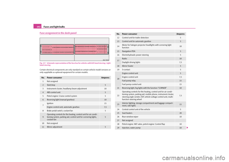
Fuse assignment in the dash panelFig. 157 Schematic representation of the fuse box for vehicles with left-hand steering / right-
hand steeringCertain electrical components are only standard on certain vehicle model versions or
only suppliable as optional equipment for certain models.No.
Power consumer
Amperes
1
Not assigned
2
Start/stop
5
3
Instrument cluster, headlamp beam adjustment
10
4
ABS control unit
5
5
Petrol engine: Cruise control system
5
6
Reversing light (manual gearbox)
10
7
Ignition
15
Engine control unit, automatic gearbox
7,5
8
Brake pedal switch, coolant fan
5
9
Operating controls for the heating, control unit for air condi-
tioning system, parking aid, control unit for cornering lights,
coolant fan
5
10
Not assigned
11
Mirror adjustment
5
12
Control unit for trailer detection
5
13
Control unit for automatic gearbox
5
14
Motor for halogen projector headlights with cornering light
function
10
15
Navigation PDA
5
16
Electrohydraulic power steering
5
17
Radio
10
Daylight driving lights
7,5
18
Mirror heater
5
19
S-contact
5
20
Engine control unit
5
Engine control unit
7,5
Fuel pump relay
15
Fuel pump control unit
15
21
Reversing light, fog lights with the function “CORNER”
10
22
Operating controls for the heating, control unit for air condi-
tioning system, parking aid, mobi le phone, instrument cluster,
steering angle sender , ESP, vehicle voltage control unit, multi-
function steering wheel
7,5
23
Interior lighting, storage compartment and luggage compart-
ment, side lights
15
24
Central control unit of the vehicle
5
25
Seat heaters
20
26
Rear window wiper
10
27
Not assigned
28
Petrol engine: AKF valve, petrol engine: Control flap
10
29
Injection, water pump
10
No.
Power consumer
Amperes
s16g.4.book Page 192 Wednesda y, February 10, 2010 3:53 PM