ECO SKODA ROOMSTER 2011 1.G Owner's Manual
[x] Cancel search | Manufacturer: SKODA, Model Year: 2011, Model line: ROOMSTER, Model: SKODA ROOMSTER 2011 1.GPages: 212, PDF Size: 3.3 MB
Page 3 of 212
Introduction
You have opted for a ŠKODA – our sincere thanks for your confidence in us.
Your new ŠKODA offers you a vehicle featuring the most modern engineering and a wide range of equipment
which you will undoubtedly wish to use to the full during your daily motoring. That is why, we recommend
that you read this Owner's Manual attentively to enable you to become familiar with your car and all that it
offers as quickly as possible.
Please do not hesitate to contact your specialist garage or importer should you have any further questions or
any problems regarding your vehicle which may arise. He will be ready at any time to receive your questions,
suggestions and criticisms.
National legal provisions, which deviate from the information contained in these operating instructions, take
precedence over the information contained in the operating instructions.
We wish you much pleasure with your ŠKODA and pleasant motoring at all times.
Your ŠKODA AUTO a.s. (hereinafter ŠKODA) £
Page 4 of 212
On-board literature
The on-board literature for your vehicle consists of this
“Owner's Man-
ual ” as well as a “Service schedule” and a “ Help on the road”. There can
also be other additional operating manuals and instructions on-board
(e. g. an operating manual for the radio) depending on the vehicle model
and equipment.
If one of the publications listed above is missing, please contact a spe-
cialist garage immediately, where one will be glad to assist you in such
matters.
One should note that the details given in the vehicle's technical docu-
mentation always take precedence over those in the Owner's Manual.
Owner's Manual
This Owner's manual describes all possible equipment variants without
identifying them as special equipment, model variants or market-de-
pendent equipment.
Consequently, this vehicle does not need to contain all of the equip-
ment components described in this Owner's manual.
The scope of equipment for your vehicle is described in the sales docu-
mentation you were given when purchasing the car. For more informa-
tion, contact your local ŠKODA retailer.
The illustrations can differ in minor details from your vehicle; they are
only intended for general information.
In addition to information regarding all the controls and equipment, the
Owner's Manual also contains important information regarding care and
operation for your safety and also to retain the value of your vehicle. To
provide you with valuable tips and aids. You will learn how you can op-
erate your vehicle safely, economically and in an environmentally con-
scious way.
For safety reasons, please also pay attention to the information on ac-
cessories, modifications and replacement of parts ⇒ page 166. The other chapters of the Owner's Manual are also important, however,
for proper treatment of your car - in addition to regular care and main-
tenance - helps to retain its value and in many cases is also one of the
conditions for possible warranty claims.
The Service schedule
Contains:
● Vehicle data;
● Service intervals;
● Overview of the service work;
● Service proof;
● Confirmation of mobility warranty (only valid in certain countries);
● important information on the warranty.
The confirmations of the carried out service work are one of the condi-
tions for possible warranty claims.
Please always present the Service schedule when you take your car to a
specialist garage.
If the Service schedule is missing or worn, please contact the specialist
garage where your car is serviced regularly. You will receive a duplicate,
in which the previously carried out service work are confirmed.
Help on the road
Contains the most important telephone numbers in individual countries
as well as the addresses and telephone numbers of
ŠKODA importers.2
Introduction
Page 5 of 212
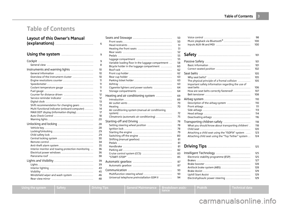
Table of Contents
Layout of this Owner's Manual
(explanations)
. . . . . . . . . . . . . . . . . . . . . . . . . . . . . . . 6
Using the system . . . . . . . . . . . . . . . . . . . . . . . . . . 9
Cockpit . . . . . . . . . . . . . . . . . . . . . . . . . . . . . . . . . . . . . . . . . . . . . 9
General view . . . . . . . . . . . . . . . . . . . . . . . . . . . . . . . . . . . . . . 8
Instruments and warning lights . . . . . . . . . . . . . . . . . . 10
General information . . . . . . . . . . . . . . . . . . . . . . . . . . . . . . . 10
Overview of the instrument cluster . . . . . . . . . . . . . . . . . 10
Engine revolutions counter . . . . . . . . . . . . . . . . . . . . . . . . . 11
Speedometer . . . . . . . . . . . . . . . . . . . . . . . . . . . . . . . . . . . . . . 11
Coolant temperature gauge . . . . . . . . . . . . . . . . . . . . . . . . 11
Fuel gauge . . . . . . . . . . . . . . . . . . . . . . . . . . . . . . . . . . . . . . . . 11
Counter for distance driven . . . . . . . . . . . . . . . . . . . . . . . . 12
Service reminder indicator . . . . . . . . . . . . . . . . . . . . . . . . . 12
Digital clock . . . . . . . . . . . . . . . . . . . . . . . . . . . . . . . . . . . . . . . 13
Shift recommendation for changing gears . . . . . . . . . . . 13
Multi-functional indicator (onboard computer) . . . . . . . 14
MAXI DOT display (information display) . . . . . . . . . . . . . . 17
Auto Check Control . . . . . . . . . . . . . . . . . . . . . . . . . . . . . . . . 18
Warning lights . . . . . . . . . . . . . . . . . . . . . . . . . . . . . . . . . . . . . 20
Unlocking and locking . . . . . . . . . . . . . . . . . . . . . . . . . . . . . 28
Vehicle key . . . . . . . . . . . . . . . . . . . . . . . . . . . . . . . . . . . . . . . . 28
Locking/Unlocking . . . . . . . . . . . . . . . . . . . . . . . . . . . . . . . . . 29
Child safety lock . . . . . . . . . . . . . . . . . . . . . . . . . . . . . . . . . . . 29
Central locking system . . . . . . . . . . . . . . . . . . . . . . . . . . . . . 30
Remote control . . . . . . . . . . . . . . . . . . . . . . . . . . . . . . . . . . . . 34
Anti-theft alarm system . . . . . . . . . . . . . . . . . . . . . . . . . . . . 35
Interior monitor and towing protection monitoring . . 36
Electrical power windows . . . . . . . . . . . . . . . . . . . . . . . . . . 36
Panorama roof . . . . . . . . . . . . . . . . . . . . . . . . . . . . . . . . . . . . 38
Lights and Visibility . . . . . . . . . . . . . . . . . . . . . . . . . . . . . . . . 39
Lights . . . . . . . . . . . . . . . . . . . . . . . . . . . . . . . . . . . . . . . . . . . . . 39
Interior lighting . . . . . . . . . . . . . . . . . . . . . . . . . . . . . . . . . . . . 43
Visibility . . . . . . . . . . . . . . . . . . . . . . . . . . . . . . . . . . . . . . . . . . 45
Windshield wiper and wash system . . . . . . . . . . . . . . . . . 46
Rear-view mirror . . . . . . . . . . . . . . . . . . . . . . . . . . . . . . . . . . 48 Seats and Stowage
. . . . . . . . . . . . . . . . . . . . . . . . . . . . . . . . 50
Front seats . . . . . . . . . . . . . . . . . . . . . . . . . . . . . . . . . . . . . . . . 50
Head restraints . . . . . . . . . . . . . . . . . . . . . . . . . . . . . . . . . . . . 51
Heating the front seats . . . . . . . . . . . . . . . . . . . . . . . . . . . . 51
Rear seats . . . . . . . . . . . . . . . . . . . . . . . . . . . . . . . . . . . . . . . . 52
Pedals . . . . . . . . . . . . . . . . . . . . . . . . . . . . . . . . . . . . . . . . . . . . 55
luggage compartment . . . . . . . . . . . . . . . . . . . . . . . . . . . . . 55
Variable loading floor in the luggage compartment . . 58
Bicycle holder in the luggage compartment . . . . . . . . . 60
Roof rack . . . . . . . . . . . . . . . . . . . . . . . . . . . . . . . . . . . . . . . . . 62
Front cup holder . . . . . . . . . . . . . . . . . . . . . . . . . . . . . . . . . . . 62
Rear cup holder . . . . . . . . . . . . . . . . . . . . . . . . . . . . . . . . . . . 63
Parking ticket holder . . . . . . . . . . . . . . . . . . . . . . . . . . . . . . . 63
Ashtray . . . . . . . . . . . . . . . . . . . . . . . . . . . . . . . . . . . . . . . . . . . 63
Cigarette lighters and power sockets . . . . . . . . . . . . . . . 64
Storage compartments . . . . . . . . . . . . . . . . . . . . . . . . . . . . 64
Heating and air conditioning system . . . . . . . . . . . . . 69
Introduction . . . . . . . . . . . . . . . . . . . . . . . . . . . . . . . . . . . . . . . 69
Air outlet vents . . . . . . . . . . . . . . . . . . . . . . . . . . . . . . . . . . . . 70
Heating . . . . . . . . . . . . . . . . . . . . . . . . . . . . . . . . . . . . . . . . . . . 70
Air conditioning system (manual air conditioning
system) . . . . . . . . . . . . . . . . . . . . . . . . . . . . . . . . . . . . . . . . . . . 72
Climatronic (automatic air conditioning) . . . . . . . . . . . . . 75
Starting-off and Driving . . . . . . . . . . . . . . . . . . . . . . . . . . . 78
Setting steering wheel position . . . . . . . . . . . . . . . . . . . . 78
Ignition lock . . . . . . . . . . . . . . . . . . . . . . . . . . . . . . . . . . . . . . . 78
Starting the engine . . . . . . . . . . . . . . . . . . . . . . . . . . . . . . . . 79
Switching off the engine . . . . . . . . . . . . . . . . . . . . . . . . . . . 80
Shifting (manual gearbox) . . . . . . . . . . . . . . . . . . . . . . . . . . 81
Pedals . . . . . . . . . . . . . . . . . . . . . . . . . . . . . . . . . . . . . . . . . . . . 81
Handbrake . . . . . . . . . . . . . . . . . . . . . . . . . . . . . . . . . . . . . . . . 81
Parking aid . . . . . . . . . . . . . . . . . . . . . . . . . . . . . . . . . . . . . . . . 82
Cruise control system (CCS) . . . . . . . . . . . . . . . . . . . . . . . . 83
“START-STOP” . . . . . . . . . . . . . . . . . . . . . . . . . . . . . . . . . . . . 85
Automatic gearbox . . . . . . . . . . . . . . . . . . . . . . . . . . . . . . . . 87
Automatic gearbox . . . . . . . . . . . . . . . . . . . . . . . . . . . . . . . . 87
Communication . . . . . . . . . . . . . . . . . . . . . . . . . . . . . . . . . . . . 93
Multifunction steering wheel . . . . . . . . . . . . . . . . . . . . . . . 93
Universal telephone preinstallation GSM II . . . . . . . . . . 94 Voice control . . . . . . . . . . . . . . . . . . . . . . . . . . . . . . . . . . . . . . 98
Music playback via Bluetooth
®
. . . . . . . . . . . . . . . . . . . . . . 100
Inputs AUX-IN and MDI . . . . . . . . . . . . . . . . . . . . . . . . . . . . 100
Safety . . . . . . . . . . . . . . . . . . . . . . . . . . . . . . . . . . . . . . . . . . . 101
Passive Safety . . . . . . . . . . . . . . . . . . . . . . . . . . . . . . . . . . . . . 101
Basic information . . . . . . . . . . . . . . . . . . . . . . . . . . . . . . . . . . 101
Correct seated position . . . . . . . . . . . . . . . . . . . . . . . . . . . . 102
Seat belts . . . . . . . . . . . . . . . . . . . . . . . . . . . . . . . . . . . . . . . . . . 105
Why seat belts? . . . . . . . . . . . . . . . . . . . . . . . . . . . . . . . . . . . 105
The physical principle of a frontal collision . . . . . . . . . . 105
Important safety information regarding the use of
seat belts
. . . . . . . . . . . . . . . . . . . . . . . . . . . . . . . . . . . . . . . . . 106
How are seat belts correctly fastened? . . . . . . . . . . . . . . 107
Belt tensioner . . . . . . . . . . . . . . . . . . . . . . . . . . . . . . . . . . . . . 108
Airbag system . . . . . . . . . . . . . . . . . . . . . . . . . . . . . . . . . . . . . . 110
Description of the airbag system . . . . . . . . . . . . . . . . . . . 110
Front airbags . . . . . . . . . . . . . . . . . . . . . . . . . . . . . . . . . . . . . . 111
Side airbags . . . . . . . . . . . . . . . . . . . . . . . . . . . . . . . . . . . . . . . 113
Head airbags . . . . . . . . . . . . . . . . . . . . . . . . . . . . . . . . . . . . . . 114
Deactivating airbags . . . . . . . . . . . . . . . . . . . . . . . . . . . . . . . 116
Transporting children safely . . . . . . . . . . . . . . . . . . . . . . 118
What you should know about transporting children! . 118
Child seat . . . . . . . . . . . . . . . . . . . . . . . . . . . . . . . . . . . . . . . . . 120
Attaching a child seat using the “ISOFIX” system . . . . 123
Attaching child seat using the “Top Tether” system . . 124
Driving Tips . . . . . . . . . . . . . . . . . . . . . . . . . . . . . . . . . . . 125
Intelligent Technology . . . . . . . . . . . . . . . . . . . . . . . . . . . . 125
Electronic stability programme (ESP) . . . . . . . . . . . . . . . . 125
Brakes . . . . . . . . . . . . . . . . . . . . . . . . . . . . . . . . . . . . . . . . . . . . 127
Brake booster . . . . . . . . . . . . . . . . . . . . . . . . . . . . . . . . . . . . . 128
Antilock brake system (ABS) . . . . . . . . . . . . . . . . . . . . . . . . 128
Brake Assist . . . . . . . . . . . . . . . . . . . . . . . . . . . . . . . . . . . . . . . 129
Uphill Start Assist . . . . . . . . . . . . . . . . . . . . . . . . . . . . . . . . . 129
Electrohydraulic power steering . . . . . . . . . . . . . . . . . . . . 129 3
Table of Contents Using the system Safety Driving Tips General Maintenance Breakdown assis-
tance Praktik Technical data
Page 6 of 212
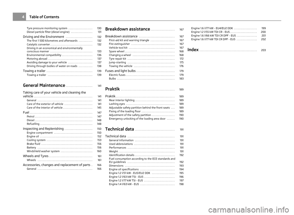
Tyre pressure monitoring system . . . . . . . . . . . . . . . . . . . 130
Diesel particle filter (diesel engine) . . . . . . . . . . . . . . . . . 131
Driving and the Environment . . . . . . . . . . . . . . . . . . . . . 132
The first 1 500 kilometres and afterwards . . . . . . . . . . . 132
Catalytic converter . . . . . . . . . . . . . . . . . . . . . . . . . . . . . . . . . 132
Driving in an economical and environmentally
conscious manner . . . . . . . . . . . . . . . . . . . . . . . . . . . . . . . . . 133
Environmental compatibility . . . . . . . . . . . . . . . . . . . . . . . . 136
Motoring abroad . . . . . . . . . . . . . . . . . . . . . . . . . . . . . . . . . . . 137
Avoiding damage to your vehicle . . . . . . . . . . . . . . . . . . . 137
Driving through bodies of water on roads . . . . . . . . . . . 138
Towing a trailer . . . . . . . . . . . . . . . . . . . . . . . . . . . . . . . . . . . . 139
Towing a trailer . . . . . . . . . . . . . . . . . . . . . . . . . . . . . . . . . . . 139
General Maintenance . . . . . . . . . . . . . . . . . . . . . 141
Taking care of your vehicle and cleaning the
vehicle . . . . . . . . . . . . . . . . . . . . . . . . . . . . . . . . . . . . . . . . . . . . . . 141
General . . . . . . . . . . . . . . . . . . . . . . . . . . . . . . . . . . . . . . . . . . . 141
Care of the exterior of vehicle . . . . . . . . . . . . . . . . . . . . . . 141
Care of the interior of vehicle . . . . . . . . . . . . . . . . . . . . . . . 145
Fuel . . . . . . . . . . . . . . . . . . . . . . . . . . . . . . . . . . . . . . . . . . . . . . . . . 147
Petrol . . . . . . . . . . . . . . . . . . . . . . . . . . . . . . . . . . . . . . . . . . . . . 147
Diesel . . . . . . . . . . . . . . . . . . . . . . . . . . . . . . . . . . . . . . . . . . . . . 148
Refuelling . . . . . . . . . . . . . . . . . . . . . . . . . . . . . . . . . . . . . . . . . 148
Inspecting and Replenishing . . . . . . . . . . . . . . . . . . . . . . 150
Engine compartment . . . . . . . . . . . . . . . . . . . . . . . . . . . . . . 150
Engine oil . . . . . . . . . . . . . . . . . . . . . . . . . . . . . . . . . . . . . . . . . 152
Cooling system . . . . . . . . . . . . . . . . . . . . . . . . . . . . . . . . . . . . 153
Brake fluid . . . . . . . . . . . . . . . . . . . . . . . . . . . . . . . . . . . . . . . . 156
Battery . . . . . . . . . . . . . . . . . . . . . . . . . . . . . . . . . . . . . . . . . . . 156
Windshield washer system . . . . . . . . . . . . . . . . . . . . . . . . . 160
Wheels and Tyres . . . . . . . . . . . . . . . . . . . . . . . . . . . . . . . . . . 161
Wheels . . . . . . . . . . . . . . . . . . . . . . . . . . . . . . . . . . . . . . . . . . . 161
Accessories, changes and replacement of parts . 166
General . . . . . . . . . . . . . . . . . . . . . . . . . . . . . . . . . . . . . . . . . . . 166 Breakdown assistance
. . . . . . . . . . . . . . . . . . . 167
Breakdown assistance . . . . . . . . . . . . . . . . . . . . . . . . . . . . 167
First-aid kit and warning triangle . . . . . . . . . . . . . . . . . . . 167
Fire extinguisher . . . . . . . . . . . . . . . . . . . . . . . . . . . . . . . . . . 167
Vehicle tool kit . . . . . . . . . . . . . . . . . . . . . . . . . . . . . . . . . . . . 167
Spare wheel . . . . . . . . . . . . . . . . . . . . . . . . . . . . . . . . . . . . . . . 168
Changing a wheel . . . . . . . . . . . . . . . . . . . . . . . . . . . . . . . . . 168
Tyre repair kit . . . . . . . . . . . . . . . . . . . . . . . . . . . . . . . . . . . . . 172
Jump-starting . . . . . . . . . . . . . . . . . . . . . . . . . . . . . . . . . . . . . 175
Towing the vehicle . . . . . . . . . . . . . . . . . . . . . . . . . . . . . . . . 176
Fuses and light bulbs . . . . . . . . . . . . . . . . . . . . . . . . . . . . . . 179
Electric fuses . . . . . . . . . . . . . . . . . . . . . . . . . . . . . . . . . . . . . . 179
Bulbs . . . . . . . . . . . . . . . . . . . . . . . . . . . . . . . . . . . . . . . . . . . . . 183
Praktik . . . . . . . . . . . . . . . . . . . . . . . . . . . . . . . . . . . . . . . . . . 189
Praktik . . . . . . . . . . . . . . . . . . . . . . . . . . . . . . . . . . . . . . . . . . . . . . 189
Rear interior lighting . . . . . . . . . . . . . . . . . . . . . . . . . . . . . . . 189
Lashing eyes . . . . . . . . . . . . . . . . . . . . . . . . . . . . . . . . . . . . . . 189
Adjustable safety partition behind the front seats . . . 189
Fixing of the loading floor . . . . . . . . . . . . . . . . . . . . . . . . . . 189
Adjustment of the safety partition . . . . . . . . . . . . . . . . . . 190
Emergency unlocking of the loading area door . . . . . . 190
Technical data . . . . . . . . . . . . . . . . . . . . . . . . . . . . . . . 191
Technical data . . . . . . . . . . . . . . . . . . . . . . . . . . . . . . . . . . . . . 191
General information . . . . . . . . . . . . . . . . . . . . . . . . . . . . . . . 191
Used abbreviations . . . . . . . . . . . . . . . . . . . . . . . . . . . . . . . . 191
Performances . . . . . . . . . . . . . . . . . . . . . . . . . . . . . . . . . . . . . 191
Weight . . . . . . . . . . . . . . . . . . . . . . . . . . . . . . . . . . . . . . . . . . . . 191
Identification details . . . . . . . . . . . . . . . . . . . . . . . . . . . . . . . 192
Fuel consumption according to the ECE standards and
EU guidelines
. . . . . . . . . . . . . . . . . . . . . . . . . . . . . . . . . . . . . 192
Dimensions . . . . . . . . . . . . . . . . . . . . . . . . . . . . . . . . . . . . . . . 193
Engine oil specifications . . . . . . . . . . . . . . . . . . . . . . . . . . . 194
Engine 1.2 l/51 kW - EU5/EU2 DDK . . . . . . . . . . . . . . . . . . 195
Engine 1.2 l/63 kW TSI - EU5 . . . . . . . . . . . . . . . . . . . . . . . . 196
Engine 1.2 l/77 kW TSI - EU5 . . . . . . . . . . . . . . . . . . . . . . . . 197
Engine 1.4 l/63 kW - EU5 . . . . . . . . . . . . . . . . . . . . . . . . . . . 198 Engine 1.6 l/77 kW - EU4/EU2 DDK . . . . . . . . . . . . . . . . . . 199
Engine 1.2 l/55 kW TDI CR - EU5 . . . . . . . . . . . . . . . . . . . . . 200
Engine 1.6 l/66 kW TDI CR DPF - EU5 . . . . . . . . . . . . . . . . 201
Engine 1.6 l/77 kW TDI CR DPF - EU5 . . . . . . . . . . . . . . . . 202
Index . . . . . . . . . . . . . . . . . . . . . . . . . . . . . . . . . . . . . . . . . . . . . 2034
Table of Contents
Page 13 of 212
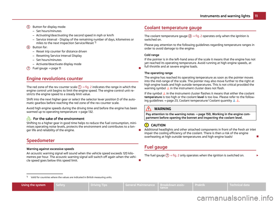
Button for display mode:
–
Set hours/minutes
– Activating/deactivating the second speed in mph or km/h
– Service interval - Display of the remaining number of days, kilometres or
miles to the next Inspection Service/Reset 1)
Button for:
– Reset trip counter for distance driven
– Resetting Service Interval Display
– Set hours/minutes
– Activate/deactivate display mode
Fuel gauge ⇒ page 11
Engine revolutions counter The red zone of the rev counter scale
1
⇒ fig. 2 indicates the range in which the
engine control unit begins to limit the engine speed. The engine control unit re-
stricts the engine speed to a steady limit value.
Shift into the next higher gear or select the selector lever position D of the auto-
matic gearbox before reaching the red zone of the rev counter scale.
Avoid high engine speeds during the driving time and before the engine has been
warmed up to operating temperature ⇒ page 132. For the sake of the environment
Shifting to a higher gear in good time helps to reduce the fuel consumption, mini-
mises operating noise levels, protects the environment and contributes to a lon-
ger life and reliability of the engine.
Speedometer Warning against excessive speeds
An acoustic warning signal will sound when the vehicle speed exceeds 120 kilo-
metres per hour. The acoustic warning signal will switch off again when the vehi-
cle speed goes below this speed limit.
5 6
7 Coolant temperature gauge
The coolant temperature gauge
4 ⇒ fig. 2
operates only when the ignition is
switched on.
Please pay attention to the following guidelines regarding temperature ranges in
order to avoid damage to the engine:
Cold range
If the pointer is in the left-hand area of the scale it means that the engine has not
yet reached its operating temperature. Avoid running at high engine speeds, at
full throttle and at severe engine loads.
The operating range
The engine has reached its operating temperature as soon as the pointer moves
into the mid-range of the scale. The pointer may also move further to the right at
high engine loads and high outside temperatures. This is not critical provided the
warning symbol in the instrument cluster does not flash.
If the symbol in the instrument cluster flashes it means that either the coolant
temperature is too high or the coolant level is too low. Please refer to the follow-
ing guidelines ⇒ page 23, Coolant temperature/ Coolant quantity . WARNING
Pay attention to the warning notes ⇒ page 150
, Working in the engine com-
partment before opening the bonnet and inspecting the coolant level. CAUTION
Additional headlights and other attached components in front of the fresh air inlet
impair the cooling efficiency of the coolant. There is then a risk of the engine
overheating at high outside temperatures and high engine loads!
Fuel gauge The fuel gauge
7
⇒
fig. 2 only operates when the ignition is switched on. £1)
Valid for countries where the values are indicated in British measuring units. 11
Instruments and warning lights Using the system Safety Driving Tips General Maintenance Breakdown assis-
tance Praktik Technical data
Page 14 of 212
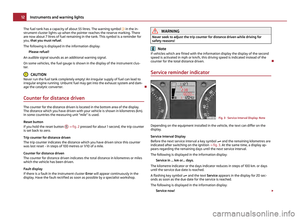
The fuel tank has a capacity of about 55 litres. The warning symbol in the in-
strument cluster lights up when the pointer reaches the reserve marking. There
are now about 7 litres of fuel remaining in the tank. This symbol is a reminder for
you, that you must refuel
.
The following is displayed in the information display: Please refuel!
An audible signal sounds as an additional warning signal.
On some vehicles, the fuel gauge is shown in the display of the instrument clus-
ter. CAUTION
Never run the fuel tank completely empty! An irregular supply of fuel can lead to
irregular engine running. Unburnt fuel may get into the exhaust system and dam-
age the catalytic converter.
Counter for distance driven The counter for the distance driven is located in the bottom area of the display.
The distance which you have driven with your vehicle is shown in kilometres (km).
In some countries the measuring unit
“mile” is used.
Reset button
If you hold the reset button 6
⇒
fig. 2 pressed for about 1 second, the trip counter
is set back to zero.
Trip counter for distance driven
The trip counter indicates the distance which you have driven since this counter
was last reset - in steps of 100 metres or 1/10 of a mile.
Counter for distance driven
The counter for distance driven indicates the total distance in kilometres or miles
which the vehicle has been driven.
Fault display
If there is a fault in the instrument cluster Error will appear continuously in the
display. Have the fault rectified as soon as possible by a specialist workshop. WARNING
Never seek to adjust the trip counter for distance driven while driving for
safety reasons! Note
If vehicles which are fitted with the information display the display of the second
speed is activated in mph or km/h, this driving speed is indicated instead of the
counter for the total distance driven.
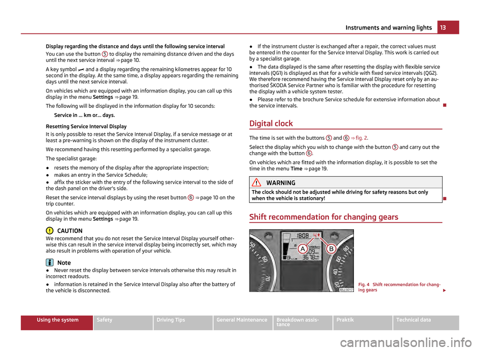
Service reminder indicator Fig. 3 Service Interval Display: Note
Depending on the equipment installed in the vehicle, the text can differ on the
display.
Service Interval Display
Before the next service interval a key symbol and the remaining kilometres are
indicated after switching on the ignition ⇒ fig. 3 . At the same time, a display ap-
pears regarding the remaining days until the next service interval.
The following is displayed in the information display:
Service in ... km or... days.
The kilometre indicator or the days indicator reduces in steps of 100 km. or days
until the service due date is reached.
A flashing key symbol and the text Service appears in the display for 20 sec-
onds as soon as the due date for the service is reached.
The following is displayed in the information display:
Service now! £12
Instruments and warning lights
Page 15 of 212
Display regarding the distance and days until the following service interval
You can use the button
5 to display the remaining distance driven and the days
until the next service interval ⇒
page 10.
A key symbol and a display regarding the remaining kilometres appear for 10
second in the display. At the same time, a display appears regarding the remaining
days until the next service interval.
On vehicles which are equipped with an information display, you can call up this
display in the menu Settings ⇒ page 19.
The following will be displayed in the information display for 10 seconds: Service in ... km or... days.
Resetting Service Interval Display
It is only possible to reset the Service Interval Display, if a service message or at
least a pre-warning is shown on the display of the instrument cluster.
We recommend having this resetting performed by a specialist garage.
The specialist garage:
● resets the memory of the display after the appropriate inspection;
● makes an entry in the Service Schedule;
● affix the sticker with the entry of the following service interval to the side of
the dash panel on the driver's side.
Reset the service interval displays by using the reset button 6
⇒ page 10 on the
trip counter.
On vehicles which are equipped with an information display, you can call up this
display in the menu Settings ⇒ page 19
. CAUTION
We recommend that you do not reset the Service Interval Display yourself other-
wise this can result in the service interval display being incorrectly set, which may
also result in problems with operation of your vehicle. Note
● Never reset the display between service intervals otherwise this may result in
incorrect readouts.
● information is retained in the Service Interval Display also after the battery of
the vehicle is disconnected. ●
If the instrument cluster is exchanged after a repair, the correct values must
be entered in the counter for the Service Interval Display. This work is carried out
by a specialist garage.
● The data displayed is the same after resetting the display with flexible service
intervals (QG1) is displayed as that for a vehicle with fixed service intervals (QG2).
We therefore recommend having the Service Interval Display reset only by an au-
thorised
ŠKODA Service Partner who is familiar with the procedure for resetting
the display with a vehicle system tester.
● Please refer to the brochure Service schedule for extensive information about
the service intervals.
Digital clock The time is set with the buttons
5 and
6
⇒
fig. 2.
Select the display which you wish to change with the button 5 and carry out the
change with the button 6 .
On vehicles which are fitted with the information display, it is possible to set the
time in the menu Time ⇒
page 19. WARNING
The clock should not be adjusted while driving for safety reasons but only
when the vehicle is stationary!
Shift recommendation for changing gears Fig. 4 Shift recommendation for chang-
ing gears
£ 13
Instruments and warning lights Using the system Safety Driving Tips General Maintenance Breakdown assis-
tance Praktik Technical data
Page 16 of 212
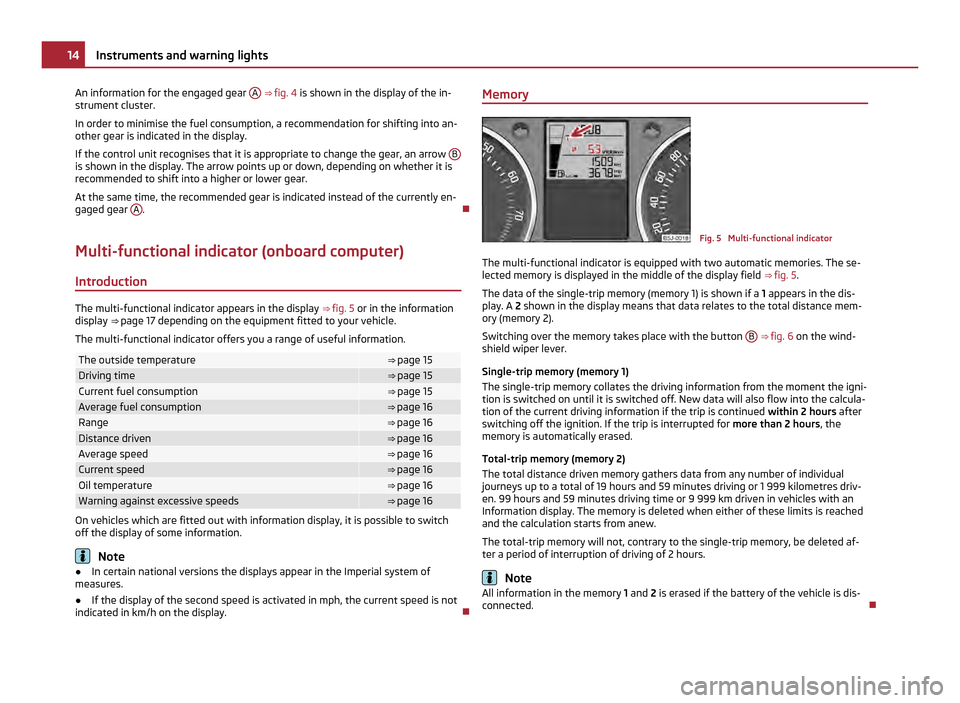
An information for the engaged gear
A
⇒ fig. 4 is shown in the display of the in-
strument cluster.
In order to minimise the fuel consumption, a recommendation for shifting into an-
other gear is indicated in the display.
If the control unit recognises that it is appropriate to change the gear, an arrow Bis shown in the display. The arrow points up or down, depending on whether it is
recommended to shift into a higher or lower gear.
At the same time, the recommended gear is indicated instead of the currently en-
gaged gear A .
Multi-functional indicator (onboard computer) Introduction The multi-functional indicator appears in the display
⇒ fig. 5 or in the information
display ⇒ page 17 depending on the equipment fitted to your vehicle.
The multi-functional indicator offers you a range of useful information. The outside temperature ⇒
page 15 Driving time ⇒
page 15 Current fuel consumption ⇒
page 15 Average fuel consumption ⇒ page 16
Range ⇒ page 16
Distance driven ⇒ page 16
Average speed ⇒ page 16
Current speed ⇒ page 16
Oil temperature ⇒ page 16
Warning against excessive speeds ⇒ page 16
On vehicles which are fitted out with information display, it is possible to switch
off the display of some information.
Note
● In certain national versions the displays appear in the Imperial system of
measures.
● If the display of the second speed is activated in mph, the current speed is not
indicated in km/h on the display. Memory
Fig. 5 Multi-functional indicator
The multi-functional indicator is equipped with two automatic memories. The se-
lected memory is displayed in the middle of the display field ⇒ fig. 5 .
The data of the single-trip memory (memory 1) is shown if a 1 appears in the dis-
play. A 2 shown in the display means that data relates to the total distance mem-
ory (memory
2).
Switching over the memory takes place with the button B
⇒ fig. 6 on the wind-
shield wiper lever.
Single-trip memory (memory 1)
The single-trip memory collates the driving information from the moment the igni-
tion is switched on until it is switched off. New data will also flow into the calcula-
tion of the current driving information if the trip is continued within 2 hours after
switching off the ignition. If the trip is interrupted for more than 2 hours, the
memory is automatically erased.
Total-trip memory (memory 2)
The total distance driven memory gathers data from any number of individual
journeys up to a total of 19 hours and 59
minutes driving or 1 999 kilometres driv-
en. 99 hours and 59 minutes driving time or 9 999 km driven in vehicles with an
Information display. The memory is deleted when either of these limits is reached
and the calculation starts from anew.
The total-trip memory will not, contrary to the single-trip memory, be deleted af-
ter a period of interruption of driving of 2 hours. Note
All information in the memory 1 and 2 is erased if the battery of the vehicle is dis-
connected. 14
Instruments and warning lights
Page 17 of 212

Using the system
Fig. 6 Multi-functional indicator: Control
elements
The rocker switch A and the button
B are located on the windshield wiper lever
⇒ fig. 6 .
Selecting the memory
– Short-term pressing of the button B on the windshield wiper lever allows to
select the desired memory.
Selecting the functions
– Press the top or bottom rocker switch A for longer than 0.5 seconds. In this
way, call up in sequence the individual functions of the multi-functional indica-
tor.
Setting function to zero
– Select the memory you want.
– Press button B for more than 1 second.
The following readouts of the selected memory will be set to zero by button B :
● average fuel consumption;
● distance driven;
● average speed;
● Driving time.
You can only operate the multi-functional indicator when the ignition is switched
on. After the ignition is switched on, the function displayed is the one which you
last selected before switching off the ignition. Outside temperature The outside temperature appears in the display when the ignition is switched on.
If the outside temperature drops below +4 °C, a snow flake symbol (warning signal
for ice on the road) appears in front of the temperature indicator and flashes for
10 seconds, then remains displayed together with the outside temperature. At the
same time an audible signal sounds. After pressing the rocker switch
A on the
windshield wiper lever ⇒
fig. 6 , the function which was shown last is indicated. WARNING
Do not only rely upon the information given on the outside temperature dis-
play that there is no ice on the road. Please note that black ice may also be
present on the road surface even at temperatures around +4
°C – warning,
drive with care!
Driving time The driving time which has elapsed since the memory was last erased, appears in
the display
⇒ page 14. If you wish to calculate the driving time from a particular
time of day you must first erase the memory at this moment in time by pressing
the button B
⇒
fig. 6
.
The maximum distance indicated in both memories is 19 hours and 59 minutes.
99 hours and 59 minutes in vehicles with an Information display. The indicator is
set back to null if this period is exceeded.
Current fuel consumption The current fuel consumption level is shown in the display in litres/100 km. This
information can help you to adapt your style of driving to the fuel consumption
you wish to achieve.
The display appears in litres/hour if the vehicle is stationary or driving at a low
speed.
The indicated value will be updated every 0.5 seconds while you are driving. 15
Instruments and warning lights Using the system Safety Driving Tips General Maintenance Breakdown assis-
tance Praktik Technical data
Page 18 of 212
Average fuel consumption
The average fuel consumption since the memory was last erased is shown in the
display in litres/100 km
⇒
page 14. This information can help you to adapt your
style of driving to the fuel consumption you wish to achieve.
If you wish to determine the average fuel consumption over a certain period of
time, you must erase the memory at the start of the new measurement using the
button B on the windshield wiper lever
⇒
fig. 6. A zero appears in the display for
the first approx. 300 m you drive after erasing the memory.
The indicated value will be updated every 5 seconds while you are driving. Note
The amount of fuel consumed will not be indicated.
Range The estimated range in kilometres is shown on the display. It indicates the dis-
tance you can still drive with your vehicle based on the present level of fuel in the
tank for the same style of driving.
The readout is shown in steps of 10 km. After lighting up of the indicator light for
the fuel reserve the display is shown in steps of 5 km.
The fuel consumption for the last 50 km is taken as a basis for calculating the
range. If you drive in a more economical manner from this moment on, the range
will be increased accordingly.
If the memory is set to zero (after disconnecting the battery), the fuel consump-
tion of 10 ltr./100 km is calculated for the range; afterwards the value is adapted
accordingly to the style of driving.
Distance driven The distance driven since the memory was last erased appears in the display
⇒
page 14. If you wish to calculate the distance driven as of a particular time, you
must erase the memory at this moment in time by pressing the button B on the
windshield wiper lever ⇒
fig. 6 .
The maximum distance indicated in both memories is 1 999 km or on vehicles with
information display, it is 9 999 km. The indicator is set back to null if this period is
exceeded. Average speed The average speed since the memory was last erased is shown in the display in
km/hour
⇒
page 14. If you wish to determine the average speed over a certain pe-
riod of time, you must erase the memory at the start of the new measurement by
pressing the button B on the windshield wiper lever
⇒ fig. 6.
A zero appears in the display for the first 100 m you drive after erasing the memo-
ry.
The indicated value will be updated every 5 seconds while you are driving.
Current speed The current speed which is identical to the display of the speedometer, is indica-
ted on the display
3
⇒
fig. 2.
Oil temperature If the oil temperature is lower than 50 °C or if a fault in the system for checking
the oil temperature is present, three lines are displayed instead of the oil temper-
ature.
Warning against excessive speeds This function enables you to set a speed limit and will notify you when this speed
limit is exceeded.
Adjust the speed limit while the vehicle is stationary
– With button A
⇒ fig. 6 , choose the menu point Warning against excessive
speeds .
– Press the button B to active the ability to set the speed limit (value flashes).
– Use the button A to adjust the required speed limit, e.g. to 50 km/h.
– Confirm the speed limit that was set with button B , or wait approx. 5 seconds
until the setting is saved automatically (the value stops flashing).
This allows you to set the speed in 5 km/h intervals.
Adjust the speed limit while the vehicle is moving
– With switch A , choose the menu point
Warning against excessive speeds. £16
Instruments and warning lights